2023 NISSAN TITAN Fuse 48
[x] Cancel search: Fuse 48Page 16 of 644
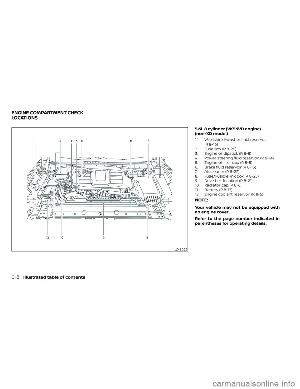
5.6L 8 cylinder (VK56VD engine)
(non-XD model)
1. Windshield-washer fluid reservoir(P. 8-16)
2. Fuse box (P. 8-25)
3. Engine oil dipstick (P. 8-8)
4. Power steering fluid reservoir (P. 8-14)
5. Engine oil filler cap (P. 8-8)
6. Brake fluid reservoir (P. 8-15)
7. Air cleaner (P. 8-22)
8. Fuse/Fusible link box (P. 8-25)
9. Drive belt location (P. 8-21)
10. Radiator cap (P. 8-6)
11. Battery (P. 8-17)
12. Engine coolant reservoir (P. 8-6)
NOTE:
Your vehicle may not be equipped with
an engine cover.
Refer to the page number indicated in
parentheses for operating details.
LDI3292
ENGINE COMPARTMENT CHECK
LOCATIONS
0-8Illustrated table of contents
Page 17 of 644
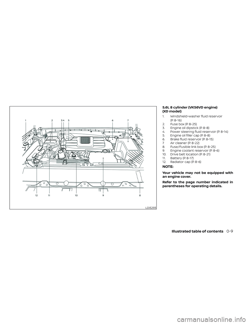
5.6L 8 cylinder (VK56VD engine)
(XD model)
1. Windshield-washer fluid reservoir(P. 8-16)
2. Fuse box (P. 8-25)
3. Engine oil dipstick (P. 8-8)
4. Power steering fluid reservoir (P. 8-14)
5. Engine oil filler cap (P. 8-8)
6. Brake fluid reservoir (P. 8-15)
7. Air cleaner (P. 8-22)
8. Fuse/Fusible link box (P. 8-25)
9. Engine coolant reservoir (P. 8-6)
10. Drive belt location (P. 8-21)
11. Battery (P. 8-17)
12. Radiator cap (P. 8-6)
NOTE:
Your vehicle may not be equipped with
an engine cover.
Refer to the page number indicated in
parentheses for operating details.
LDI3293
Illustrated table of contents0-9
Page 140 of 644
NOTE:
Opening and closing a rear door while
stopped will reset this warning, similar to
pushing the ignition switch to ON again.
NOTE:
In vehicles with only 2 seats in the rear
row, only 2 seats will be displayed.
Release Parking Brake
This warning appears in the message area
of the vehicle information display when the
parking brake is set and the vehicle is
driven. Press the brake pedal to release the
parking brake.
Reminder: Turn OFF
Headlights
This warning appears when the headlights
are lef t in the ON position when exiting the
vehicle. Place the headlight switch in the
OFF or AUTO position. For additional infor-
mation, see “Headlight control switch”
(P. 2-45).
Remote Engine Start Mode
This warning appears in the vehicle infor-
mation display when the vehicle has been
started using the remote start function. Tostart the vehicle, apply the brake and place
the ignition switch in the ON position.
Shif t to Park
This warning appears when the ignition
switch is in the ACC or OFF position and the
shif t lever is not in the P (Park) position. Also,
a chime sounds when the ignition switch is
in the ACC or OFF position.
If this warning appears, move the shif t lever
to the P (Park) position and start the engine.
Shipping Mode On Push Storage Fuse
This warning may appear if the extended
storage switch is not pushed in. When this
warning appears, push in the extended
storage switch to turn off the warning. For
additional information, see “Extended stor-
age switch” (P. 2-71).
Tire Pressure Low - Add Air
This warning appears when the low tire
pressure warning light in the meter illumi-
nates and low tire pressure is detected. The
warning appears each time the ignition
switch is placed in the ON position as long
as the low tire pressure warning light re-
mains illuminated. If this warning appears,
stop the vehicle and adjust the tire pres-
sures of all four tires to the recommended
COLD tire pressure shown on the Tire and
Loading Information label. For additional
information, see “Low tire pressure warning
light” (P. 2-20) and “Tire Pressure Monitoring
System (TPMS)” (P. 5-5).
TPMS Error: See Owner’s Manual
This warning appears when there is an er-
ror with your TPMS. If this warning appears,
have the system checked. It is recom-
mended that you visit a NISSAN dealer for
this service.
When parked apply parking
brake
This message appears when a malfunc-
tion occurs in the electric shif t control sys-
tem below 3 mph (5 km/h).
Have the system checked. It is recom-
mended that you visit a NISSAN dealer for
this service.
4WD Error: See Owner’s
Manual
This warning appears when the 4-wheel
drive system is not functioning properly
while the engine is running.
2-36Instruments and controls
Page 172 of 644
•Push the plug in as far as it will go. If
good contact is not made, the plug
may overheat or the internal tem-
perature fuse may open.
• When not in use, be sure to close the
cap. Do not allow water or any other
liquid to contact the outlet.
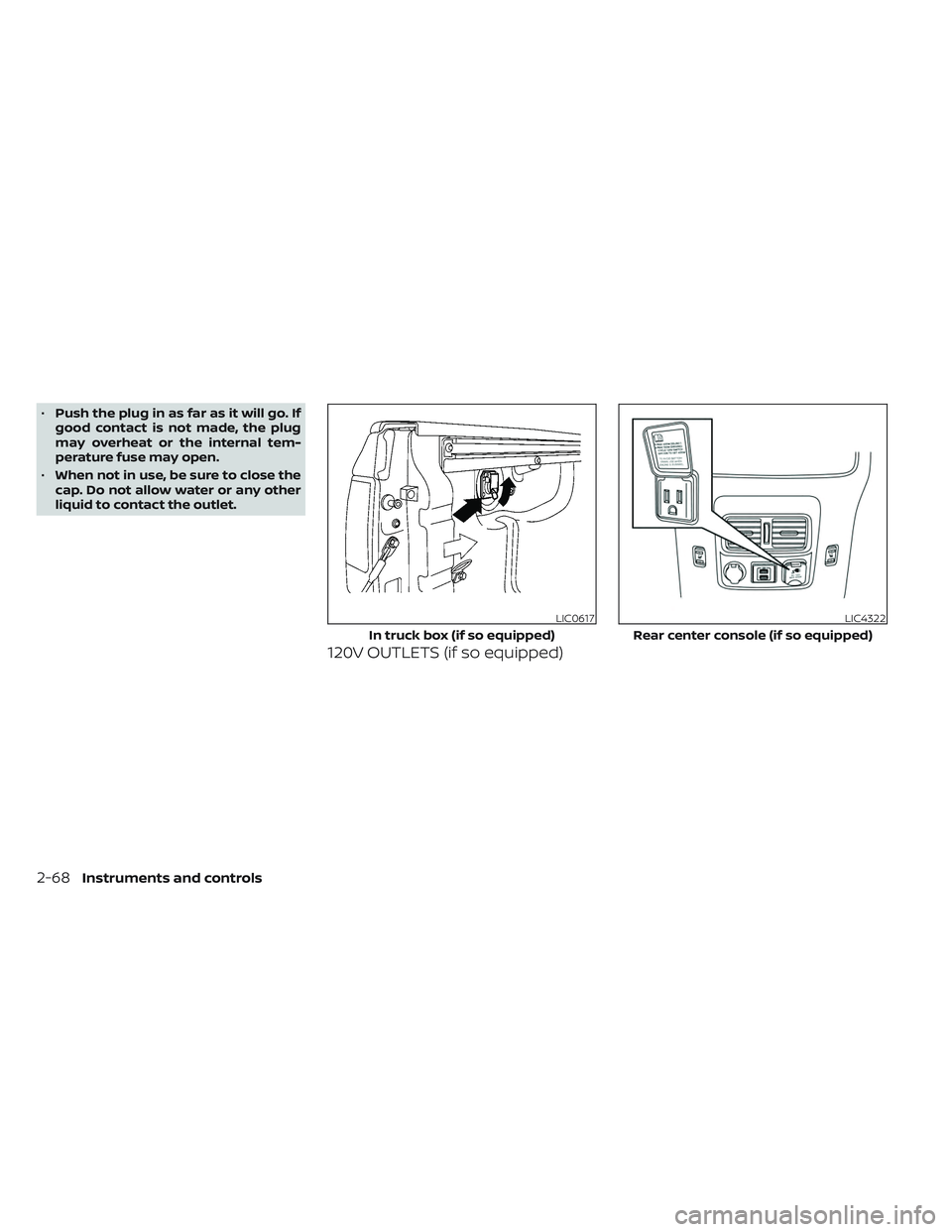
120V OUTLETS (if so equipped)
LIC0617
In truck box (if so equipped)
LIC4322
Rear center console (if so equipped)
2-68Instruments and controls
Page 174 of 644
Do not use the outlet located in the truck
box with accessories that exceed 120 volt.
Do not use double adapters or more than
one electrical accessory. When the dual
wall bed liner is installed (if so equipped),
the power outlet is still accessible through
the access door in the bed liner.
CAUTION
• Operation of the 120 volt system with
the ignition in the ON position and
the engine not running (idle) will
drain the battery charge. This could
lead to a dead battery or no start
condition.
• The outlet and plug may be hot dur-
ing or immediately af ter use.
• Use power outlets with the engine
running to avoid discharging the ve-
hicle battery.
• Do not use double adaptors or more
than one electrical accessory.
• Avoid using power outlets when the
air conditioner, headlights or rear
window defroster is on.
• Before inserting or disconnecting a
plug, be sure the electrical accessory
being used is turned OFF. •
Push the plug in as far as it will go. If
good contact is not made, the plug
may overheat or the internal tem-
perature fuse may open.
• When not in use, be sure to close the
cap. Do not allow water or any other
liquid to contact the outlet.
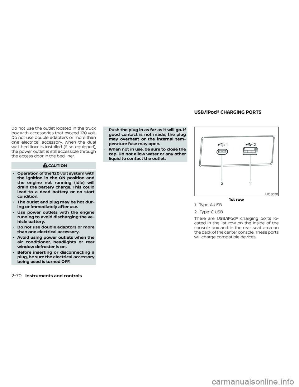
1. Type-A USB
2. Type-C USB
There are USB/iPod® charging ports lo-
cated in the 1st row on the inside of the
console box and in the rear seat area on
the back of the center console. These ports
will charge compatible devices.
LIC5070
1st row
USB/iPod® CHARGING PORTS
2-70Instruments and controls
Page 176 of 644
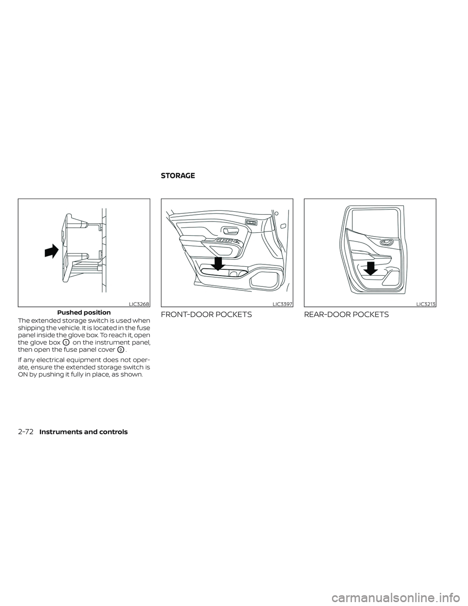
The extended storage switch is used when
shipping the vehicle. It is located in the fuse
panel inside the glove box. To reach it, open
the glove box
O1on the instrument panel,
then open the fuse panel cover
O2.
If any electrical equipment does not oper-
ate, ensure the extended storage switch is
ON by pushing it fully in place, as shown.
FRONT-DOOR POCKETS REAR-DOOR POCKETS
LIC3268
Pushed position
LIC3397LIC3213
STORAGE
2-72Instruments and controls
Page 249 of 644
ENTRY/EXIT FUNCTION
This system is designed so that the driver's
seat and steering column will automati-
cally move when the shif t lever is in the P
(Park) position. This allows the driver to
easily get in and out of the driver’s seat.
The driver’s seat will slide backward and
the steering column will move up:
• When the driver’s door is opened with theignition switch in the OFF position.
• When the ignition switch is changed from ACC to OFF with the driver’s door open.
The driver’s seat and steering wheel will
return to the previous position:
• When the ignition switch is changed from ACC or ON while the shif t lever is in the P
(Park) position.
The entry/exit function can be adjusted or
canceled through the vehicle settings in
the vehicle information display by perform-
ing the following:
• Switch the Exit Seat Slide from ON to OFF.
• Switch the Exit Steering UP from ON to OFF.
Restarting the entry/exit function
If the battery cable is disconnected, or if the
fuse opens, the stored memory positions
will be lost and some of the functions will
be restricted:
1. Drive the vehicle over 25 mph (40 km/h).
OR
2. Open and close the driver's door more than two times with the ignition switch
in the OFF position.
The entry/exit function should now work
properly.
SYSTEM OPERATION
The memory seat system will not work or
will stop operating under the following
conditions:
• When the vehicle speed is above 4 mph (7 km/h).
• When any of the memory switches are pushed while the memory seat system is
operating. • When the switch for the driver’s seat and
steering column is pushed while the
memory seat system is operating.
• When the seat has already been moved to the memorized position.
• When no seat position is stored in the memory switch.
• When the shif t lever is moved from P (Park) to any other position.
The memory seat system can be adjusted
and canceled. It is recommended you visit
a NISSAN dealer for this service.
Pre-driving checks and adjustments3-43
Page 326 of 644

TROUBLESHOOTING
SymptomRemedy
Monitor does not power on Verif y the vehicle is in the ON or ACC position.
Verif y the battery is installed correctly in the remote control.
Verif y the in-line fuse protection is good. Refer to the RSI system installation instructions for vehicle-specific fuse location.
Monitor front panel controls
flash red For further diagnosis, it is recommended that you visit a NISSAN dealer.
System frozen - will not re-
spond Sof t reset the system by pressing and holding the power button on the top of the driver side monitor for 5 seconds.
Hard reset the system by turning the ignition off, then back on.
No picture Check that the signal source is connected.
Check the menu source setting. Match your monitor mode with the source correctly.
No sound or distorted sound Make sure that the external media device is connected properly, and all cables are securely inserted into the appropriate jacks.
Verif y that the batteries in the headphones are fresh.
If you are using the wireless headphones, make sure you turn on the power and select the correct monitor (A or B).
Verif y the volume is turned up on headphones and the system.
Verif y nothing is blocking the path between the monitor IR sensor and headphones.
When placing the headphones on your head, make sure to observe the Lef t and Right orientation. The headphones must be ori-
ented correctly (facing forward) to receive the audio signal.
Monitor feels warm When the monitor is in use for a long period of time, the surface will be warm. This is normal.
A Parental Setting message
is displayed, prohibiting
movie playback Enter the 4-digit Parental Password using the remote and then press
. For additional information, see “Changing parental
lock” (P. 4-75).
Cannot connect mobile de-
vice to the internal RSI Wi-Fi
network Check to make sure Wi-Fi is enabled on the mobile device.
Check to make sure RSI is set to Access Point mode.
Check to make sure the correct password is used. For additional information, see “Using Wi-Fi” (P. 4-68).
Cannot connect RSI system
to an external Wi-Fi network Check to make sure RSI is set to Client Mode. Check to make sure the correct password is used. For additional information, see
“Using Wi-Fi” (P. 4-68).
4-76Monitor, climate, audio, phone and voice recognition systems