2023 NISSAN SENTRA fuel
[x] Cancel search: fuelPage 206 of 556
•Underneath the bumper and the cor-
ner areas of the bumper cannot be
viewed on the RearView Monitor be-
cause of its monitoring range limita-
tion. The system will not show small
objects below the bumper, and may
not show objects close to the bum-
per or on the ground.
• Objects viewed in the RearView
Monitor differ from actual distance
because a wide-angle lens is used.
• Objects in the RearView Monitor will
appear visually opposite compared
to when viewed in the rearview and
outside mirrors.
• Use the displayed lines as a refer-
ence. The lines are highly affected by
the number of occupants, fuel level,
vehicle position, road conditions and
road grade.
• Make sure that the trunk is securely
closed when backing up.
• Do not put anything on the rearview
camera. The rearview camera is in-
stalled above the license plate. •
When washing the vehicle with high
pressure water, be sure not to spray it
around the camera. Otherwise, water
may enter the camera unit causing
water condensation on the lens, a
malfunction, fire or an electric shock.
• Do not strike the camera. It is a preci-
sion instrument. Otherwise, it may
malfunction or cause damage result-
ing in a fire or an electric shock.
The following are operating limitations and
do not represent a system malfunction:
• When the temperature is extremely high or low, the screen may not clearly display
objects.
• When strong light directly shines on the camera, objects may not be displayed
clearly.
• Vertical lines may be seen in objects on the screen. This is due to strong reflected
light from the bumper.
• The screen may flicker under fluorescent light.
• The colors of objects on the RearView Monitor may differ somewhat from the
actual color of objects.
• Objects on the monitor may not be clear in a dark environment. • There may be a delay when switching
between views.
• If dirt, rain or snow accumulate on the camera, the RearView Monitor may not
display objects clearly. Clean the camera.
• Do not use wax on the camera lens. Wipe off any wax with a clean cloth dampened
with a diluted mild cleaning agent, then
wipe with a dry cloth.
4-14Monitor, climate, audio, phone and voice recognition systems
Page 210 of 556
The screen displayed on the Intelligent
Around View® Monitor will automatically re-
turn to the previous screen 3 minutes af ter
the CAMERA button has been pressed with
the shif t lever in a position other than the R
(Reverse) position.
Available views
WARNING
• The distance guide lines and the ve-
hicle width lines should be used as a
reference only when the vehicle is on
a paved, level surface. The apparent
distance viewed on the monitor may
be different than the actual distance
between the vehicle and displayed
objects.
• Use the displayed lines and the
bird’s-eye view as a reference. The
lines and the bird’s-eye view are
greatly affected by the number of oc-
cupants, cargo, fuel level, vehicle po-
sition, road condition and road
grade.
• If the tires are replaced with different
sized tires, the predicted course lines
and the bird's-eye view may be dis-
played incorrectly. •
When driving the vehicle up a hill, ob-
jects viewed in the monitor are fur-
ther than they appear. When driving
the vehicle down a hill, objects
viewed in the monitor are closer than
they appear.
• Objects in the rear view will appear
visually opposite compared to when
viewed in the monitor and outside
mirrors.
• Use the mirrors or actually look to
properly judge distances to other
objects.
• On a snow-covered or slippery road,
there may be a difference between
the predicted course lines and the
actual course line.
• The vehicle width and predicted
course lines are wider than the actual
width and course.
• The displayed lines will appear
slightly off to the right, because the
rearview camera is not installed in
the rear center of the vehicle.
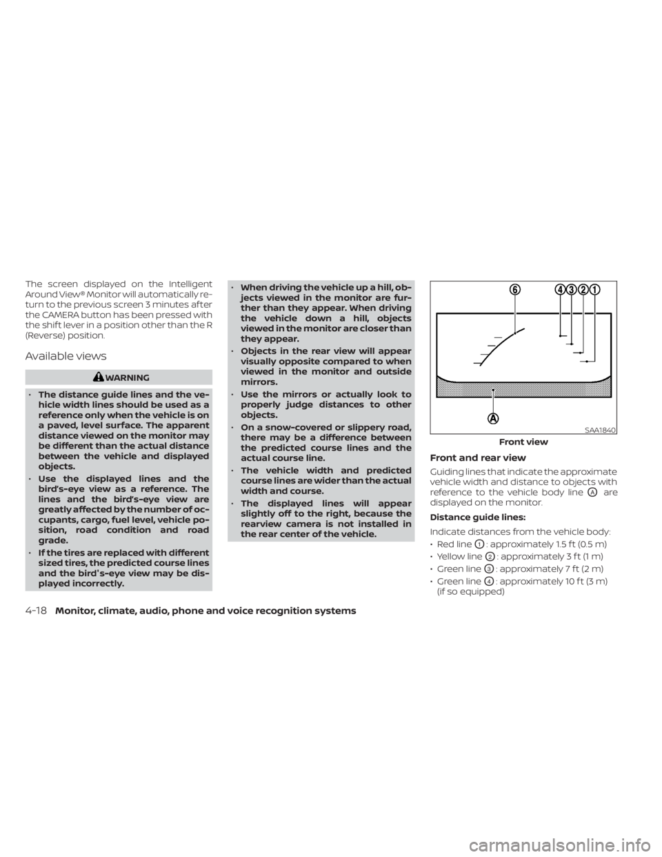
Front and rear view
Guiding lines that indicate the approximate
vehicle width and distance to objects with
reference to the vehicle body line
OAare
displayed on the monitor.
Distance guide lines:
Indicate distances from the vehicle body:
• Red line
O1: approximately 1.5 f t (0.5 m)
• Yellow line
O2: approximately 3 f t (1 m)
• Green line
O3: approximately 7 f t (2 m)
• Green line
O4: approximately 10 f t (3 m)
(if so equipped)
SAA1840
Front view
4-18Monitor, climate, audio, phone and voice recognition systems
Page 279 of 556
Intelligent Driver Alertness (I-DA)...............5-121
Intelligent Driver Alertness system
operation .................................. 5-121
How to enable/disable the Intelligent
Driver Alertness (I-DA) system ..............5-122
Intelligent Driver Alertness (I-DA)
system limitations ......................... 5-123
Break-in schedule ............................. 5-125
Fuel efficient driving tips .......................5-125
Increasing fuel economy ......................5-126
Parking/parking on hills .......................5-127
Power steering ................................ 5-128
Brake system ................................. 5-129
Brake precautions .......................... 5-129
Anti-lock Braking System (ABS) .............5-129
Brake Assist ................................ 5-131
Vehicle Dynamic Control (VDC) system ........5-131
Rise-up and build-up ....................... 5-132
Brake force distribution ....................5-132
Chassis Control ............................... 5-133Intelligent Trace Control
....................5-133
Active Ride Control ......................... 5-134
Intelligent Engine Brake ....................5-134
Hill start assist system ........................5-135
Rear Sonar System (RSS) ......................5-135
System operation .......................... 5-136
How to enable/disable the sonar
system ..................................... 5-138
Sonar limitations ........................... 5-140
System temporarily unavailable ............5-140
System maintenance ......................5-140
Cold weather driving .......................... 5-141
Freeing a frozen door lock ..................5-141
Antifreeze .................................. 5-141
Battery..................................... 5-141
Draining of coolant water ..................5-141
Tire equipment ............................. 5-141
Special winter equipment ..................5-142
Driving on snow or ice ......................5-142
Engine
block heater (if so equipped) ........5-142
Page 281 of 556
CAUTION
• Do not use leaded gasoline. Deposits
from leaded gasoline will seriously
reduce the three-way catalyst's abil-
ity to help reduce exhaust pollutants.
• Keep your engine tuned up. Malfunc-
tions in the ignition, fuel injection, or
electrical systems can cause overrich
fuel flow into the three-way catalyst,
causing it to overheat. Do not keep
driving if the engine misfires, or if no-
ticeable loss of performance or other
unusual operating conditions are de-
tected. Have the vehicle inspected
promptly. It is recommended that
you visit a NISSAN dealer for this
service.
• Avoid driving with an extremely low
fuel level. Running out of fuel could
cause the engine to misfire, damag-
ing the three-way catalyst.
• Do not race the engine while warm-
ing it up.
• Do not push or tow your vehicle to
start the engine.TIRE PRESSURE MONITORING
SYSTEM (TPMS)
Each tire, including the spare (if provided),
should be checked monthly when cold and
inflated to the inflation pressure recom-
mended by the vehicle manufacturer on
the vehicle placard or tire inflation pressure
label. (If your vehicle has tires of a different
size than the size indicated on the vehicle
placard or tire inflation pressure label, you
should determine the proper tire inflation
pressure for those tires.)
As an added safety feature, your vehicle
has been equipped with a Tire Pressure
Monitoring System (TPMS) that illuminates
a low tire pressure telltale when one or
more of your tires is significantly under-
inflated. Accordingly, when the low tire
pressure telltale illuminates, you should
stop and check all your tires as soon as
possible, and inflate them to the proper
pressure. Driving on a significantly under-
inflated tire causes the tire to overheat and
can lead to tire failure. Under-inflation also
reduces fuel efficiency and tire tread life,
and may affect the vehicle’s handling and
stopping ability. Please note that the TPMS is not a substi-
tute for proper tire maintenance, and it is
the driver’s responsibility to maintain cor-
rect tire pressure, even if under-inflation
has not reached the level to trigger illumi-
nation of the TPMS low tire pressure telltale.
Your vehicle has also been equipped with a
TPMS malfunction indicator to indicate
when the system is not operating properly.
The TPMS malfunction indicator is com-
bined with the low tire pressure telltale.
When the system detects a malfunction,
the telltale will flash for approximately one
minute and then remain continuously illu-
minated. This sequence will continue upon
subsequent vehicle start-ups as long as
the malfunction exists. When the malfunc-
tion indicator is illuminated, the system
may not be able to detect or signal low tire
pressure as intended. TPMS malfunctions
may occur for a variety of reasons, includ-
ing the installation of replacement or alter-
nate tires or wheels on the vehicle that
prevent the TPMS from functioning prop-
erly. Always check the TPMS malfunction
telltale af ter replacing one or more tires or
wheels on your vehicle to ensure that the
replacement or alternate tires and wheels
allow the TPMS to continue to function
properly.
Starting and driving5-5
Page 290 of 556
NISSAN VEHICLE IMMOBILIZER
SYSTEM
The NISSAN Vehicle Immobilizer System
will not allow the engine to start without
the use of the registered key.
If the engine fails to start using a registered
key (for example, when interference is
caused by another registered key, an auto-
mated toll road device or automatic pay-
ment device on the key ring), restart the
engine using the following procedure:
1. Leave the ignition switch in the ON posi-tion for approximately 5 seconds.
2. Place the ignition switch in the OFF or LOCK position, and wait approximately
10 seconds.
3. Repeat steps 1 and 2.
4. Restart the engine while holding the de- vice (which may have caused the inter-
ference) separate from the registered
key.
If the no start condition re-occurs, NISSAN
recommends placing the registered key on
a separate key ring to avoid interference
from other devices. • Make sure the area around the vehicle is
clear.
• Check fluid levels such as engine oil, cool- ant, brake and clutch fluid (if so equipped),
and windshield-washer fluid as fre-
quently as possible, or at least whenever
you refuel.
• Check that all windows and lights are clean.
• Visually inspect tires for their appearance and condition. Also check tires for proper
inflation.
• Lock all doors.
• Position seat and adjust head restraints/headrests.
• Adjust inside and outside mirrors.
• Fasten seat belts and ask all passengers to do likewise.
• Check the operation of warning lights when the ignition switch is placed in the
ON position. For additional information,
see “Warning lights, indicator lights and
audible reminders” (P. 2-9). 1. Apply the parking brake.
2.
Continuously Variable Transmission
model:
Move the shif t lever to P (Park) or N (Neu-
tral). P (Park) is recommended.
The starter is designed not to operate
if the shif t lever is in any of the driving
positions.
Manual Transmission (M/T) model:
Move the shif t lever to N (Neutral). De-
press the clutch pedal to the floor.
The starter is designed not to operate
unless the clutch pedal is fully
depressed.
3. Push the ignition switch to the ON posi- tion. Depress the brake pedal and the
clutch pedal (if so equipped) and push
the ignition switch to start the engine.
To start the engine immediately, push
and release the ignition switch while de-
pressing the brake pedal with the igni-
tion switch in any position.
BEFORE STARTING THE ENGINE STARTING THE ENGINE
5-14Starting and driving
Page 296 of 556
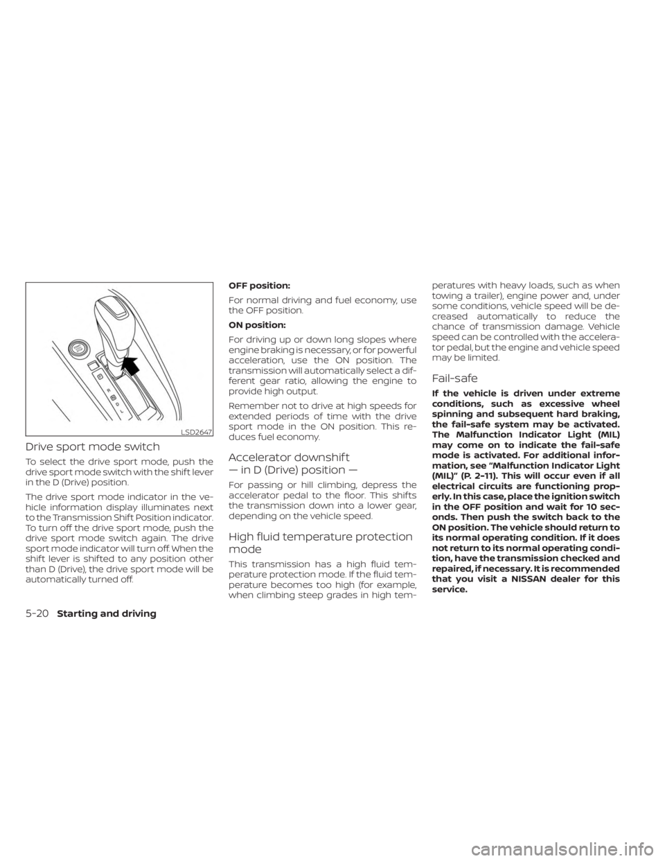
Drive sport mode switch
To select the drive sport mode, push the
drive sport mode switch with the shif t lever
in the D (Drive) position.
The drive sport mode indicator in the ve-
hicle information display illuminates next
to the Transmission Shif t Position indicator.
To turn off the drive sport mode, push the
drive sport mode switch again. The drive
sport mode indicator will turn off. When the
shif t lever is shif ted to any position other
than D (Drive), the drive sport mode will be
automatically turned off.OFF position:
For normal driving and fuel economy, use
the OFF position.
ON position:
For driving up or down long slopes where
engine braking is necessary, or for powerful
acceleration, use the ON position. The
transmission will automatically select a dif-
ferent gear ratio, allowing the engine to
provide high output.
Remember not to drive at high speeds for
extended periods of time with the drive
sport mode in the ON position. This re-
duces fuel economy.Accelerator downshif t
— in D (Drive) position —
For passing or hill climbing, depress the
accelerator pedal to the floor. This shif ts
the transmission down into a lower gear,
depending on the vehicle speed.
High fluid temperature protection
mode
This transmission has a high fluid tem-
perature protection mode. If the fluid tem-
perature becomes too high (for example,
when climbing steep grades in high tem-peratures with heavy loads, such as when
towing a trailer), engine power and, under
some conditions, vehicle speed will be de-
creased automatically to reduce the
chance of transmission damage. Vehicle
speed can be controlled with the accelera-
tor pedal, but the engine and vehicle speed
may be limited.
Fail-safe
If the vehicle is driven under extreme
conditions, such as excessive wheel
spinning and subsequent hard braking,
the fail-safe system may be activated.
The Malfunction Indicator Light (MIL)
may come on to indicate the fail-safe
mode is activated. For additional infor-
mation, see “Malfunction Indicator Light
(MIL)” (P. 2-11). This will occur even if all
electrical circuits are functioning prop-
erly. In this case, place the ignition switch
in the OFF position and wait for 10 sec-
onds. Then push the switch back to the
ON position. The vehicle should return to
its normal operating condition. If it does
not return to its normal operating condi-
tion, have the transmission checked and
repaired, if necessary. It is recommended
that you visit a NISSAN dealer for this
service.
LSD2647
5-20Starting and driving
Page 298 of 556
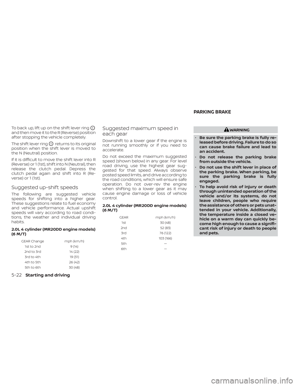
To back up, lif t up on the shif t lever ringO1
and then move it to the R (Reverse) position
af ter stopping the vehicle completely.
The shif t lever ring
O1returns to its original
position when the shif t lever is moved to
the N (Neutral) position.
If it is difficult to move the shif t lever into R
(Reverse) or 1 (1st), shif t into N (Neutral), then
release the clutch pedal. Depress the
clutch pedal again and shif t into R (Re-
verse) or 1 (1st).
Suggested up-shif t speeds
The following are suggested vehicle
speeds for shif ting into a higher gear.
These suggestions relate to fuel economy
and vehicle performance. Actual upshif t
speeds will vary according to road condi-
tions, the weather and individual driving
habits.
2.0L 4 cylinder (MR20DD engine models)
(6 M/T)
GEAR Change mph (km/h)
1st to 2nd 9 (14)
2nd to 3rd 14 (22)
3rd to 4th 19 (31)
4th to 5th 26 (42)
5th to 6th 30 (48)
Suggested maximum speed in
each gear
Downshif t to a lower gear if the engine is
not running smoothly or if you need to
accelerate.
Do not exceed the maximum suggested
speed (shown below) in any gear. For level
road driving, use the highest gear sug-
gested for that speed. Always observe
posted speed limits, and drive according to
the road conditions, which will ensure safe
operation. Do not over-rev the engine
when shif ting to a lower gear as it may
cause engine damage or loss of vehicle
control.
2.0L 4 cylinder (MR20DD engine models)
(6 M/T)
GEARmph (km/h)
1st 30 (48)
2nd 52 (83)
3rd 76 (122)
4th 103 (166)
5th —
6th —
WARNING
• Be sure the parking brake is fully re-
leased before driving. Failure to do so
can cause brake failure and lead to
an accident.
• Do not release the parking brake
from outside the vehicle.
• Do not use the shif t lever in place of
the parking brake. When parking, be
sure the parking brake is fully
engaged.
• To help avoid risk of injury or death
through unintended operation of the
vehicle and/or its systems, do not
leave children, people who require
the assistance of others or pets unat-
tended in your vehicle. Additionally,
the temperature inside a closed ve-
hicle on a warm day can quickly be-
come high enough to cause a signifi-
cant risk of injury or death to people
and pets.
PARKING BRAKE
5-22Starting and driving
Page 300 of 556
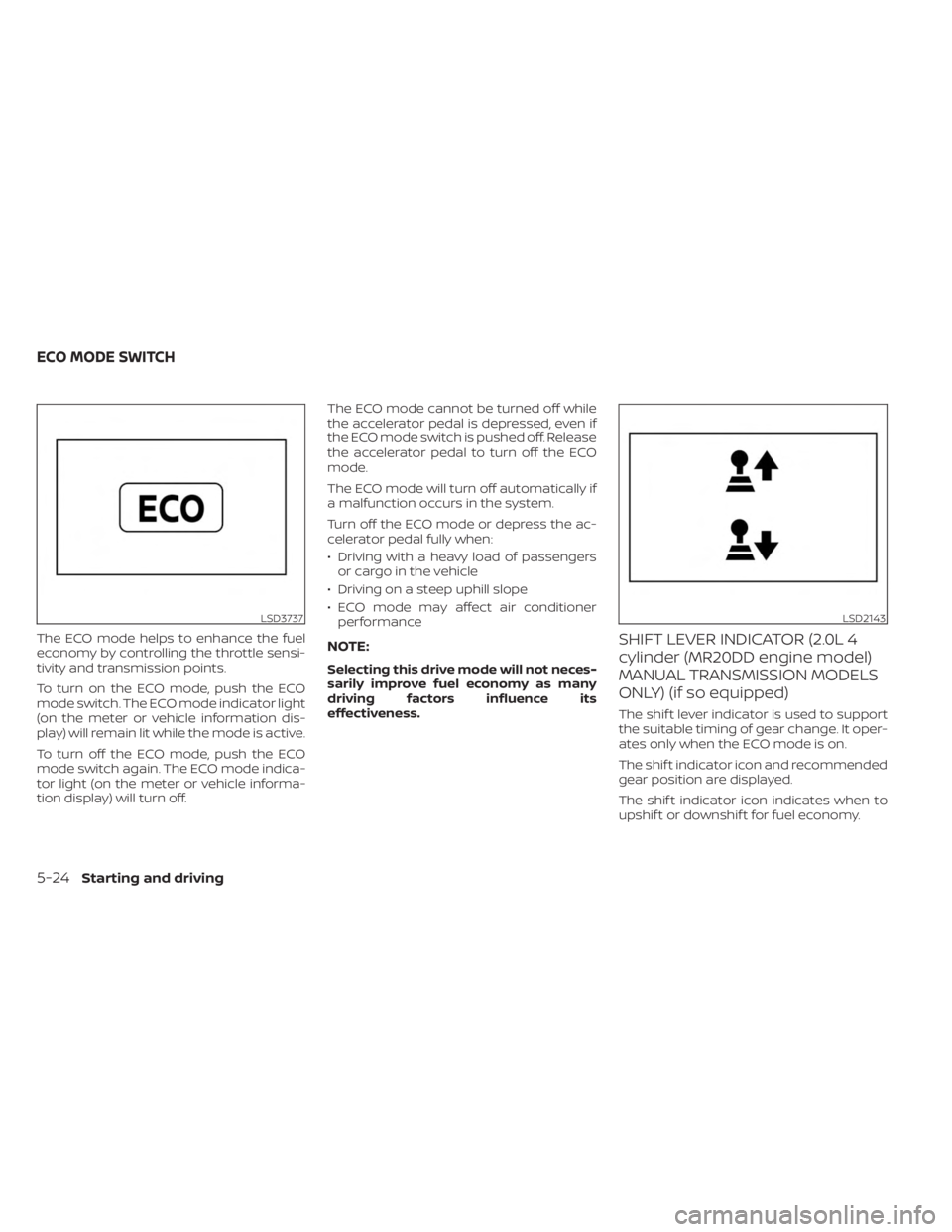
The ECO mode helps to enhance the fuel
economy by controlling the throttle sensi-
tivity and transmission points.
To turn on the ECO mode, push the ECO
mode switch. The ECO mode indicator light
(on the meter or vehicle information dis-
play) will remain lit while the mode is active.
To turn off the ECO mode, push the ECO
mode switch again. The ECO mode indica-
tor light (on the meter or vehicle informa-
tion display) will turn off.The ECO mode cannot be turned off while
the accelerator pedal is depressed, even if
the ECO mode switch is pushed off. Release
the accelerator pedal to turn off the ECO
mode.
The ECO mode will turn off automatically if
a malfunction occurs in the system.
Turn off the ECO mode or depress the ac-
celerator pedal fully when:
• Driving with a heavy load of passengers
or cargo in the vehicle
• Driving on a steep uphill slope
• ECO mode may affect air conditioner performanceNOTE:
Selecting this drive mode will not neces-
sarily improve fuel economy as many
driving factors influence its
effectiveness.
SHIFT LEVER INDICATOR (2.0L 4
cylinder (MR20DD engine model)
MANUAL TRANSMISSION MODELS
ONLY) (if so equipped)
The shif t lever indicator is used to support
the suitable timing of gear change. It oper-
ates only when the ECO mode is on.
The shif t indicator icon and recommended
gear position are displayed.
The shif t indicator icon indicates when to
upshif t or downshif t for fuel economy.
LSD3737LSD2143
ECO MODE SWITCH
5-24Starting and driving