Page 122 of 508

2-40Instruments and controls
JVI1566X
TRIP COMPUTER
The trip computer display can be chan-
ged using the buttons OK,,,
andlocated on the steering
wheel.
OK - change or select an item in the
vehicle information display
- navigate through the items in vehi-
cle information display
- go back to the previous menu- change from one display screen
to the next
1. Safety Shield
The safety shield mode shows the oper-
ating condition for the following systems.
. Lane Departure Warning (LDW)
. Intelligent Lane Intervention (I-LI)
. Blind Spot Warning (BSW)
. Automatic Emergency Braking (AEB)
with Pedestrian Detection system
For more details, see “Lane Departure
Warning (LDW)” (P.5-35), “Intelligent Lane
Intervention (I-LI)” (P.5-40), “Blind Spot
Warning (BSW)” (P.5-46) or “Automatic
Emergency Braking (AEB) with Pedestrian
Detection system” (P.5-97).
2. Average speed 1 and 2 (MPH or
km/h)
The average speed 1 mode shows the
average vehicle speed since the last reset.
The average speed 2 mode shows the
average vehicle speed since the time the
ignition switch was turned ON. The aver-
age speed 2 is automatically reset each
time the ignition is placed in the OFF
position.
Resetting is done by pushing the OK
button. When the OKbutton is pushed,
the following menu items are displayed. .
Cancel
— Return to the previous screen with-
out resetting.
. Average Speed
— Reset the average speed.
. All
— Reset all items of “Average Speed”,
“Elapsed time and trip odometer”
and “Fuel economy.”
Once the “Average speed 1” is displayed,
you can use
buttons to switch
between the “Average speed 1” and “Aver-
age speed 2.”
The display is updated every 30 seconds.
The first 30 seconds after a reset, the
display shows “——”.
3. Elapsed time and trip odometer 1
and 2 (mile or km)
Elapsed time:
The elapsed time mode 1 shows the time
since the last reset. The elapsed time 2
mode shows the time since the ignition
switch was turned ON. (The trip odometer
is also reset at the same time.)
Trip odometer:
The trip odometer 1 mode shows the total
distance the vehicle has been driven since
the last reset. The trip odometer 2 mode
shows the total distance the vehicle has
Page 141 of 508
JVI0980X
Example
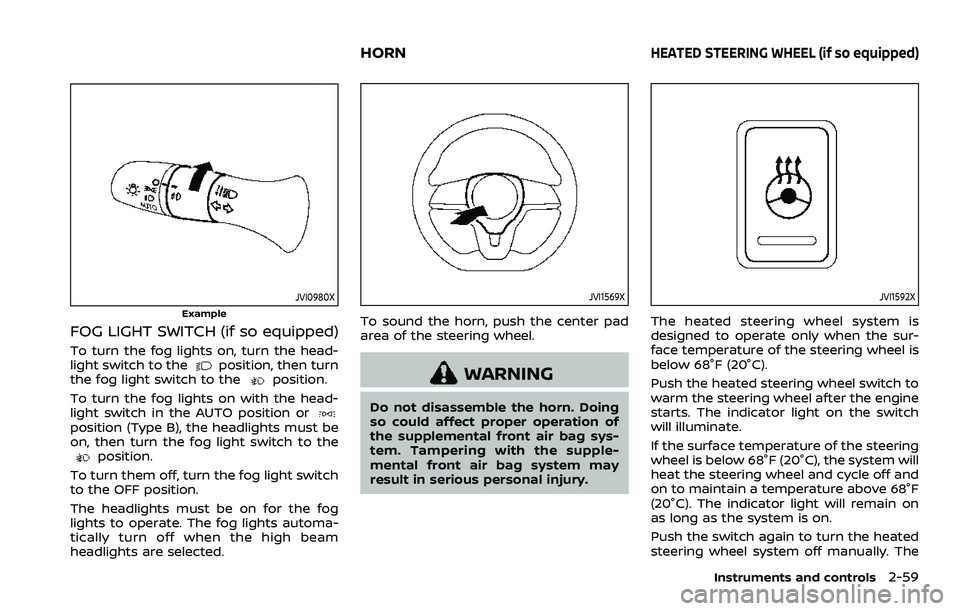
FOG LIGHT SWITCH (if so equipped)
To turn the fog lights on, turn the head-
light switch to theposition, then turn
the fog light switch to theposition.
To turn the fog lights on with the head-
light switch in the AUTO position or
position (Type B), the headlights must be
on, then turn the fog light switch to the
position.
To turn them off, turn the fog light switch
to the OFF position.
The headlights must be on for the fog
lights to operate. The fog lights automa-
tically turn off when the high beam
headlights are selected.
JVI1569X
To sound the horn, push the center pad
area of the steering wheel.
WARNING
Do not disassemble the horn. Doing
so could affect proper operation of
the supplemental front air bag sys-
tem. Tampering with the supple-
mental front air bag system may
result in serious personal injury.
JVI1592X
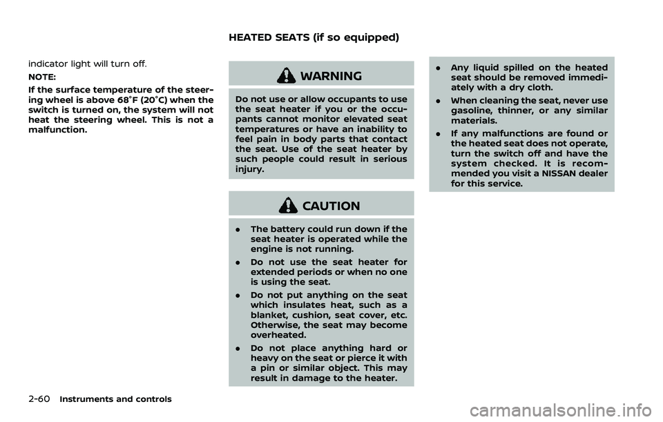
The heated steering wheel system is
designed to operate only when the sur-
face temperature of the steering wheel is
below 68°F (20°C).
Push the heated steering wheel switch to
warm the steering wheel after the engine
starts. The indicator light on the switch
will illuminate.
If the surface temperature of the steering
wheel is below 68°F (20°C), the system will
heat the steering wheel and cycle off and
on to maintain a temperature above 68°F
(20°C). The indicator light will remain on
as long as the system is on.
Push the switch again to turn the heated
steering wheel system off manually. The
Instruments and controls2-59
HORNHEATED STEERING WHEEL (if so equipped)
Page 142 of 508
2-60Instruments and controls
indicator light will turn off.
NOTE:
If the surface temperature of the steer-
ing wheel is above 68°F (20°C) when the
switch is turned on, the system will not
heat the steering wheel. This is not a
malfunction.
WARNING
Do not use or allow occupants to use
the seat heater if you or the occu-
pants cannot monitor elevated seat
temperatures or have an inability to
feel pain in body parts that contact
the seat. Use of the seat heater by
such people could result in serious
injury.
CAUTION
.The battery could run down if the
seat heater is operated while the
engine is not running.
. Do not use the seat heater for
extended periods or when no one
is using the seat.
. Do not put anything on the seat
which insulates heat, such as a
blanket, cushion, seat cover, etc.
Otherwise, the seat may become
overheated.
. Do not place anything hard or
heavy on the seat or pierce it with
a pin or similar object. This may
result in damage to the heater. .
Any liquid spilled on the heated
seat should be removed immedi-
ately with a dry cloth.
. When cleaning the seat, never use
gasoline, thinner, or any similar
materials.
. If any malfunctions are found or
the heated seat does not operate,
turn the switch off and have the
system checked. It is recom-
mended you visit a NISSAN dealer
for this service.
HEATED SEATS (if so equipped)
Page 144 of 508
2-62Instruments and controls
the brakes to the left or right wheels
individually (for a short period of time). For
additional information, see “Intelligent
Lane Intervention (I-LI)” (P.5-40).
WAC0074X
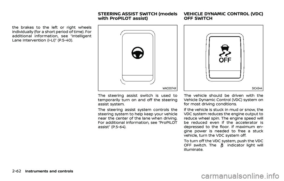
The steering assist switch is used to
temporarily turn on and off the steering
assist system.
The steering assist system controls the
steering system to help keep your vehicle
near the center of the lane when driving.
For additional information, see “ProPILOT
assist” (P.5-64).
SIC4544
The vehicle should be driven with the
Vehicle Dynamic Control (VDC) system on
for most driving conditions.
If the vehicle is stuck in mud or snow, the
VDC system reduces the engine output to
reduce wheel spin. The engine speed will
be reduced even if the accelerator is
depressed to the floor. If maximum en-
gine power is needed to free a stuck
vehicle, turn the VDC system off.
To turn off the VDC system, push the VDC
OFF switch. The
indicator light will
illuminate.
STEERING ASSIST SWITCH (models
with ProPILOT assist) VEHICLE DYNAMIC CONTROL (VDC)
OFF SWITCH
Page 200 of 508
3-30Pre-driving checks and adjustments
JVP0503X
LOOSE FUEL CAP warning message
The LOOSE FUEL CAP warning messageis displayed on the vehicle information
display when the fuel-filler cap is not
tightened correctly after the vehicle has
been refueled. It may take a few driving
trips for the message to be displayed. To
turn off the warning message, do the
following procedure:
1. Remove and install the fuel-filler capas soon as possible. For additional
information, refer to “Fuel-filler cap”
(P.3-28).
2. Tighten the fuel-filler cap until it clicks. 3. Push the OK button
on the steering
wheel for about 1 second to turn off
the LOOSE FUEL CAP warning mes-
sage after tightening the fuel cap.
WARNING
Do not adjust the steering wheel
while driving. You could lose control
of your vehicle and cause an acci-
dent.
TILT/TELESCOPIC STEERING
Page 201 of 508
JVP0301X
TILT OR TELESCOPIC OPERATION
Pull the lock leverdown and adjust the
steering wheel up, down, forward or
rearward to the desired position. Push
the lock lever up securely to lock the
steering wheel in place.
SIC3739
1. To block glare from the front, swing down the main sun visor.
2. To block glare from the side, remove the main sun visor from the center
mount and swing it to the side
.
3. Slide the sun visor
in or out as
needed.
CAUTION
. Do not store the sun visor before
returning the extension to its
original position.
. Do not pull the extension sun
visor forcedly downward.
Pre-driving checks and adjustments3-31
SUN VISORS
Page 210 of 508
4-4Monitor, heater, air conditioner, audio and phone systems
JVH1585X
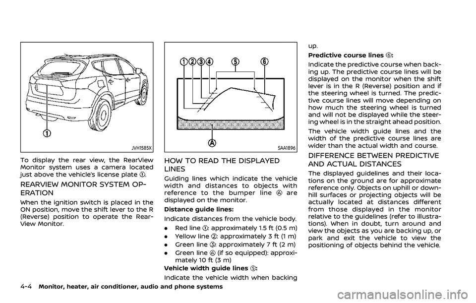
To display the rear view, the RearView
Monitor system uses a camera located
just above the vehicle’s license plate
.
REARVIEW MONITOR SYSTEM OP-
ERATION
When the ignition switch is placed in the
ON position, move the shift lever to the R
(Reverse) position to operate the Rear-
View Monitor.
SAA1896
HOW TO READ THE DISPLAYED
LINES
Guiding lines which indicate the vehicle
width and distances to objects with
reference to the bumper line
are
displayed on the monitor.
Distance guide lines:
Indicate distances from the vehicle body.
. Red line
: approximately 1.5 ft (0.5 m)
. Yellow line
: approximately 3 ft (1 m)
. Green line
: approximately 7 ft (2 m)
. Green line
(if so equipped): approxi-
mately 10 ft (3 m)
Vehicle width guide lines
:
Indicate the vehicle width when backing up.
Predictive course lines
:
Indicate the predictive course when back-
ing up. The predictive course lines will be
displayed on the monitor when the shift
lever is in the R (Reverse) position and if
the steering wheel is turned. The predic-
tive course lines will move depending on
how much the steering wheel is turned
and will not be displayed while the steer-
ing wheel is in the straight ahead position.
The vehicle width guide lines and the
width of the predictive course lines are
wider than the actual width and course.
DIFFERENCE BETWEEN PREDICTIVE
AND ACTUAL DISTANCES
The displayed guidelines and their loca-
tions on the ground are for approximate
reference only. Objects on uphill or down-
hill surfaces or projecting objects will be
actually located at distances different
from those displayed in the monitor
relative to the guidelines (refer to illustra-
tions). When in doubt, turn around and
view the objects as you are backing up, or
park and exit the vehicle to view the
positioning of objects behind the vehicle.
Page 212 of 508
4-6Monitor, heater, air conditioner, audio and phone systems
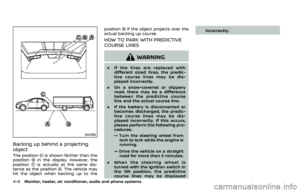
SAA1980
Backing up behind a projecting
object
The positionis shown farther than the
positionin the display. However, the
positionis actually at the same dis-
tance as the position. The vehicle may
hit the object when backing up to the position
if the object projects over the
actual backing up course.
HOW TO PARK WITH PREDICTIVE
COURSE LINES
WARNING
. If the tires are replaced with
different sized tires, the predic-
tive course lines may be dis-
played incorrectly.
. On a snow-covered or slippery
road, there may be a difference
between the predictive course
line and the actual course line.
. If the battery is disconnected or
becomes discharged, the predic-
tive course lines may be dis-
played incorrectly. If this occurs,
please perform the following pro-
cedures:
— Turn the steering wheel from
lock to lock while the engine is
running.
— Drive the vehicle on a straight road for more than 5 minutes.
. When the steering wheel is
turned with the ignition switch in
the ON position, the predictive
course lines may be displayed incorrectly.