2023 NISSAN QASHQAI brake
[x] Cancel search: brakePage 124 of 508
2-42Instruments and controls
10. Chassis control
When Intelligent Trace Control, Intelligent
Engine Brake (Continuously Variable
Transmission (CVT) models) or Active Ride
Control system is operated, it shows the
operating condition. It also shows oper-
ating condition of Hill Start Assist. The
operating condition of the automatic
brake hold function (if so equipped) is
also shown. See “Intelligent Trace Control”
(P.5-133), “Intelligent Engine Brake (Con-
tinuously Variable Transmission (CVT)
models)” (P.5-134), “Active Ride Control”
(P.5-135), “Hill Start Assist system” (P.5-136)
or “Automatic brake hold” (P.5-29) for
more details.
11. Tire Pressures
The tire pressure mode shows the pres-
sure of all four tires while the vehicle is
driven.
When the Tire Pressure Low — Add Air
warning appears, the display can be
switched to the tire pressure mode by
pushing the OK
button to reveal addi-
tional details on the displayed warning.
12. Intelligent Driver Alertness (I-DA)
system (if so equipped)
When the “Driver Attention” display is
selected, you can view your attention
level as detected by the system. (See
“Intelligent Driver Alertness (I-DA)” (P.5-
94).)
13. Traffic Sign Recognition (if so
equipped)
The Traffic Sign Recognition (TSR) system
provides the driver with information
about the most recently detected speed
limit. See “Traffic Sign Recognition” (P.2-
43) for more details.
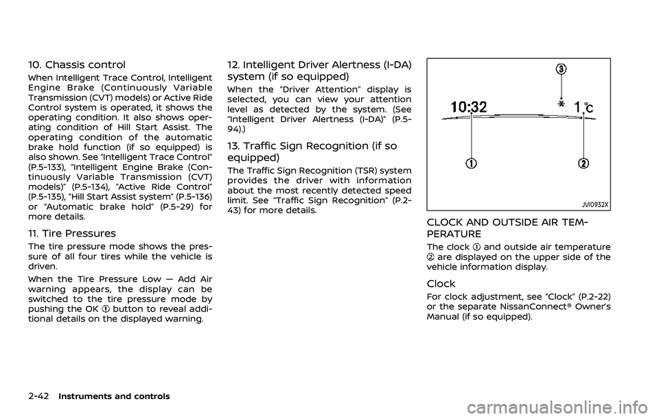
JVI0932X
CLOCK AND OUTSIDE AIR TEM-
PERATURE
The clockand outside air temperatureare displayed on the upper side of the
vehicle information display.
Clock
For clock adjustment, see “Clock” (P.2-22)
or the separate NissanConnect® Owner’s
Manual (if so equipped).
Page 135 of 508
To turn the Intelligent Auto Headlight
system off, turn the switch to the OFF,
orposition.
The Intelligent Auto Headlight system can
turn on the headlights automatically
when it is dark and turn off the headlights
when it is light.
The headlights will also be turned on
automatically at twilight or in rainy
weather (when the windshield wiper is
operated continuously).
If the ignition switch is placed in the OFF
position and one of the doors is opened
and this condition is continued, the head-
lights remain on for 5 minutes.
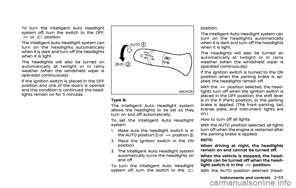
WAC0412X
Type B:
The Intelligent Auto Headlight system
allows the headlights to be set so they
turn on and off automatically.
To set the Intelligent Auto Headlight
system:
1. Make sure the headlight switch is in the AUTO position
orposition.
2. Place the ignition switch in the ON position.
3. The Intelligent Auto Headlight system automatically turns the headlights on
and off.
To turn the Intelligent Auto Headlight
system off, turn the switch to the
position.
The Intelligent Auto Headlight system can
turn on the headlights automatically
when it is dark and turn off the headlights
when it is light.
The headlights will also be turned on
automatically at twilight or in rainy
weather (when the windshield wiper is
operated continuously).
If the ignition switch is turned to the ON
position when the parking brake is ap-
plied, the headlights remain off.
With the
position selected, the head-
lights turn off when the ignition switch is
placed in the OFF position, the shift lever
is in the P (Park) position, or the parking
brake is applied. (The front parking, tail,
license plate, and instrument lights are
on.)
How to turn off all lights:
With the AUTO position selected, all lights
turn off when the engine is restarted after
the parking brake is applied.
NOTE:
When driving at night, the headlights
remain on and cannot be turned off.
When the vehicle is stopped, the head-
lights can be turned off when the head-
light switch is in the
position.
With the AUTO position selected (head-
Instruments and controls2-53
Page 139 of 508
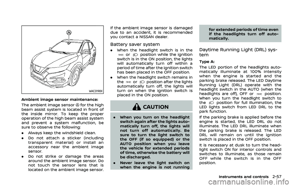
WAC0198X
Ambient image sensor maintenance:
The ambient image sensor
for the high
beam assist system is located in front of
the inside mirror. To keep the proper
operation of the high beam assist system
and prevent a system malfunction, be
sure to observe the following:
. Always keep the windshield clean.
. Do not attach a sticker (including
transparent material) or install an
accessory near the ambient image
sensor.
. Do not strike or damage the areas
around the ambient image sensor. Do
not touch the sensor lens that is
located on the ambient image sensor. If the ambient image sensor is damaged
due to an accident, it is recommended
you contact a NISSAN dealer.
Battery saver system
.
When the headlight switch is in theorposition while the ignition
switch is in the ON position, the lights
will automatically turn off within a
period of time after the ignition switch
has been placed in the OFF position.
. When the headlight switch remains in
the
orposition after the lights
automatically turn off, the lights will
turn on when the ignition switch is
placed in the ON position.
CAUTION
. When you turn on the headlight
switch again after the lights auto-
matically turn off, the lights will
not turn off automatically. Be
sure to turn the light switch to
the OFF (if so equipped) or the
AUTO position when you leave
the vehicle for extended periods
of time, otherwise the battery will
be discharged.
. Never leave the light switch on
when the engine is not running for extended periods of time even
if the headlights turn off auto-
matically.
Daytime Running Light (DRL) sys-
tem
Type A:
The LED portion of the headlights auto-
matically illuminate at 100% intensity
when the engine is started and the
parking brake released. The LED Daytime
Running Light (DRL) operate with the
headlight switch in the AUTO (when the
headlights are off), OFF or
position.
When you turn the headlight switch to
the
position for full illumination, the
LED lights switch from LED DRL to the
park function.
If the parking brake is applied before the
engine is started, the LED DRL do not
illuminate. The LED DRL illuminate when
the parking brake is released. The LED
DRL will remain on until the ignition
switch is placed in the OFF position.
It is necessary at dusk to turn the head-
light switch ON for interior controls and
switches to illuminate, as those remain
OFF while the switch is in the OFF
position.
Instruments and controls2-57
Page 140 of 508
2-58Instruments and controls
WARNING
When the LED DRL system is active,
tail lights on your vehicle are not on.
It is necessary at dusk to turn on
your headlights. Failure to do so
could cause an accident injuring
yourself and others.
Type B:
The LED portion of the headlights auto-
matically illuminate at 100% intensity
when the engine is started and the
parking brake released. The DRL operate
with the headlight switch in the AUTO
position or
position, the headlight
must be off. When you turn the headlight
switch to the
position for full illumi-
nation, the LED lights switch from LED
DRL to the park function.
If the parking brake is applied before the
engine is started, the LED DRL do not
illuminate. The LED DRL illuminate when
the parking brake is released. The LED
DRL will remain on until the ignition
switch is placed in the OFF position or
the headlight turns on.
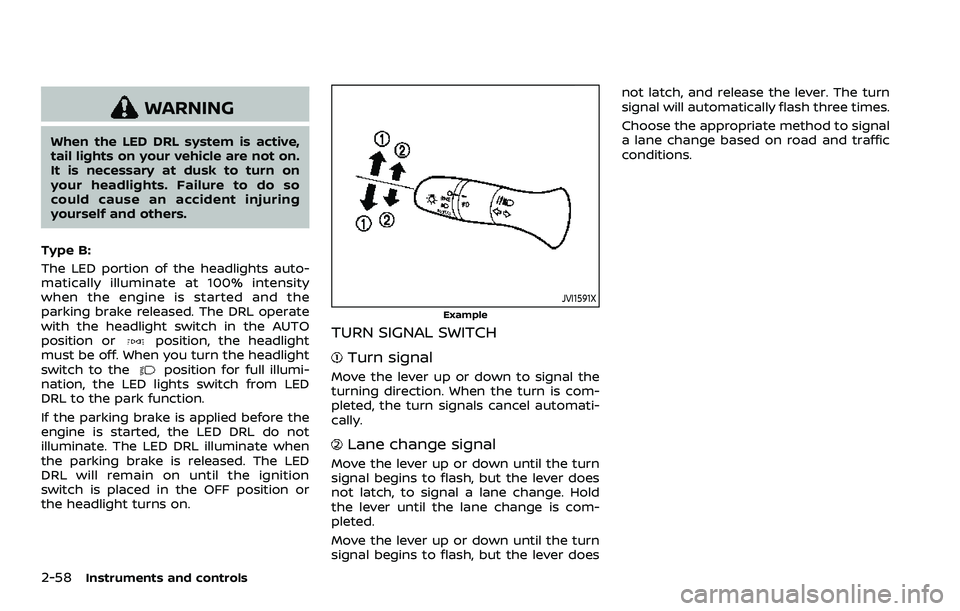
JVI1591X
Example
TURN SIGNAL SWITCH
Turn signal
Move the lever up or down to signal the
turning direction. When the turn is com-
pleted, the turn signals cancel automati-
cally.
Lane change signal
Move the lever up or down until the turn
signal begins to flash, but the lever does
not latch, to signal a lane change. Hold
the lever until the lane change is com-
pleted.
Move the lever up or down until the turn
signal begins to flash, but the lever does not latch, and release the lever. The turn
signal will automatically flash three times.
Choose the appropriate method to signal
a lane change based on road and traffic
conditions.
Page 144 of 508
2-62Instruments and controls
the brakes to the left or right wheels
individually (for a short period of time). For
additional information, see “Intelligent
Lane Intervention (I-LI)” (P.5-40).
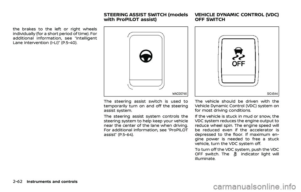
WAC0074X
The steering assist switch is used to
temporarily turn on and off the steering
assist system.
The steering assist system controls the
steering system to help keep your vehicle
near the center of the lane when driving.
For additional information, see “ProPILOT
assist” (P.5-64).
SIC4544
The vehicle should be driven with the
Vehicle Dynamic Control (VDC) system on
for most driving conditions.
If the vehicle is stuck in mud or snow, the
VDC system reduces the engine output to
reduce wheel spin. The engine speed will
be reduced even if the accelerator is
depressed to the floor. If maximum en-
gine power is needed to free a stuck
vehicle, turn the VDC system off.
To turn off the VDC system, push the VDC
OFF switch. The
indicator light will
illuminate.
STEERING ASSIST SWITCH (models
with ProPILOT assist) VEHICLE DYNAMIC CONTROL (VDC)
OFF SWITCH
Page 149 of 508

EMERGENCY SUPPORT
NissanConnect® Services provides var-
ious services to support dealing with
emergencies of the subscribed vehicle
and the driver.
For example, in case of an illness or
serious injury, you can seek support by
pushing the in-vehicle Emergency Call
(SOS) button and connecting to Nissan-
Connect® Services. NissanConnect® Ser-
vices can specify the location of the
vehicle via GPS, and the information will
be sent to the police or other agencies as
needed.
For information about other NissanCon-
nect® Services emergency support re-
lated services, refer to the
NissanConnect® Services website or con-
tact the NissanConnect® Customer Sup-
port Line.
NissanConnect® Services website:
For U.S.
www.nissanusa.com/connect
For Canada
http://www.nissan.ca/nissanconnect
(English)
www.nissan.ca/nissanconnect/fr
(French)NissanConnect® Customer Support Line:
1-855-426-6628
WARNING
.
Please note that the Automatic
Collision Notification service and
Emergency Call function cannot
be used in the following condi-
tions:
— Emergency functions and ser-
vices will not be available
without a paid subscription
to NissanConnect® Services.
— The NissanConnect® Services network system is disabled.
— The vehicle moves outside the service area where the TCU
(Telematics Control Unit) is
connected to the system.
— The vehicle is outside the area where the cellular network
service is receivable.
— The vehicle is in a location with poor signal reception
such as tunnels, underground
parking garages, behind
buildings or in mountainous
areas. — The line is busy.
— The TCU (Telematics Control
Unit) or other systems of your
vehicle are not working prop-
erly.
— It may not be possible to make an emergency call de-
pending on the severity of a
collision and/or emergency.
. Park the vehicle in a safe location
and set the parking brake before
operating the Emergency Call
(SOS) button.
. Only use this service in case of an
emergency. There may be a pen-
alty for inappropriate use of the
service.
. Radio waves could adversely af-
fect electric medical equipment.
Individuals who use pacemakers
should contact the device manu-
facturer regarding any possible
effects before using the system.
. The TCU (Telematics Control Unit)
antenna is installed inside the
upper central part of the instru-
ment panel. An occupant should
not get any closer to the antenna
than specified by the pacemaker
manufacturer. The radio waves
Instruments and controls2-67
EMERGENCY CALL (SOS) BUTTON
(if so equipped)
Page 155 of 508
JVI1686X
Cargo area
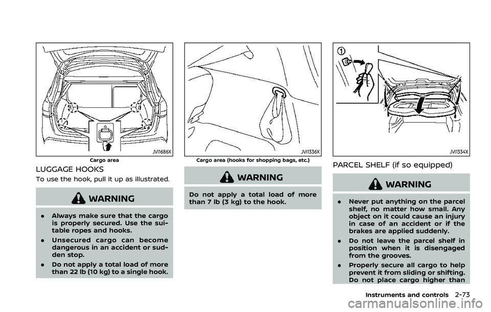
LUGGAGE HOOKS
To use the hook, pull it up as illustrated.
WARNING
.Always make sure that the cargo
is properly secured. Use the sui-
table ropes and hooks.
. Unsecured cargo can become
dangerous in an accident or sud-
den stop.
. Do not apply a total load of more
than 22 lb (10 kg) to a single hook.
JVI1336X
Cargo area (hooks for shopping bags, etc.)
WARNING
Do not apply a total load of more
than 7 lb (3 kg) to the hook.
JVI1334X
PARCEL SHELF (if so equipped)
WARNING
.Never put anything on the parcel
shelf, no matter how small. Any
object on it could cause an injury
in case of an accident or if the
brakes are applied suddenly.
. Do not leave the parcel shelf in
position when it is disengaged
from the grooves.
. Properly secure all cargo to help
prevent it from sliding or shifting.
Do not place cargo higher than
Instruments and controls2-73
Page 194 of 508

3-24Pre-driving checks and adjustments
3. Within 5 seconds push and hold theremote engine startbutton until
the turn signal lights flash and the tail
lights illuminate. If the vehicle is not
within view, push and hold the remote
engine start
button for at least 2
seconds.
The following events will occur when the
engine starts:
. The front parking lights will turn on
and remain on as long as the engine is
running.
. The doors will be locked and the air
conditioner system may turn on.
. The engine will continue to run for
about 10 minutes. Repeat the steps to
extend the time for an additional 10
minutes. See “Extending engine run
time” (P.3-24).
Depress and hold the brake pedal, then
place the ignition switch in the ON posi-
tion before driving. For further instruc-
tions, see “Driving the vehicle” (P.5-20).
EXTENDING ENGINE RUN TIME
The remote engine start function can be
extended one time by performing the
steps listed in “Remote starting the en-
gine” (P.3-23). Run time will be calculated
as follows:
. The first 10 minute run time will start
when the remote engine start func- tion is performed.
. The second 10 minutes will start im-
mediately when the remote engine
start function is performed. For exam-
ple, if the engine has been running for
5 minutes, and 10 minutes are added,
the engine will run for a total of 15
minutes.
. Extending engine run time will count
towards the two remote engine start
limit.
A maximum of two remote engine starts,
or a single start with an extension, are
allowed between ignition cycles.
The ignition switch must be cycled to the
ON position and then back to the OFF
position before the remote engine start
procedure can be used again.
CANCELING A REMOTE ENGINE
START
To cancel a remote engine start, perform
one of the following:
. Aim the Intelligent Key at the vehicle
and push and hold the remote engine
start
button until the front park-
ing lights turn off.
. Turn on the hazard indicator flashers.
. Cycle the ignition switch ON and then
OFF. .
The extended engine run time has
expired.
. The first 10 minute timer has expired.
. The engine hood has been opened.
. The shift lever is moved out of the P
(Park) position.
. The theft alarm sounds due to illegal
entry into the vehicle.
. The ignition switch is pushed without
an Intelligent Key in the vehicle.
. The ignition switch is pushed with an
Intelligent Key in the vehicle but the
brake pedal is not depressed.
CONDITIONS THE REMOTE ENGINE
START WILL NOT WORK
The remote engine start will not operate
if any of the following conditions are
present:
.The ignition switch is placed in the ON
position.
. The hood is not securely closed.
. The hazard indicator flashers are on.
. The engine is still running. The engine
must be completely stopped. Wait at
least 6 seconds if the engine goes
from running to off. This is not applic-
able when extending engine run time.
. The remote engine start
button is
not pushed and held for at least 2
seconds.