2023 NISSAN QASHQAI radio
[x] Cancel search: radioPage 193 of 508
WARNING
To avoid risk of injury or death, do
not use the remote engine start
function when the vehicle is in an
enclosed area such as a garage.
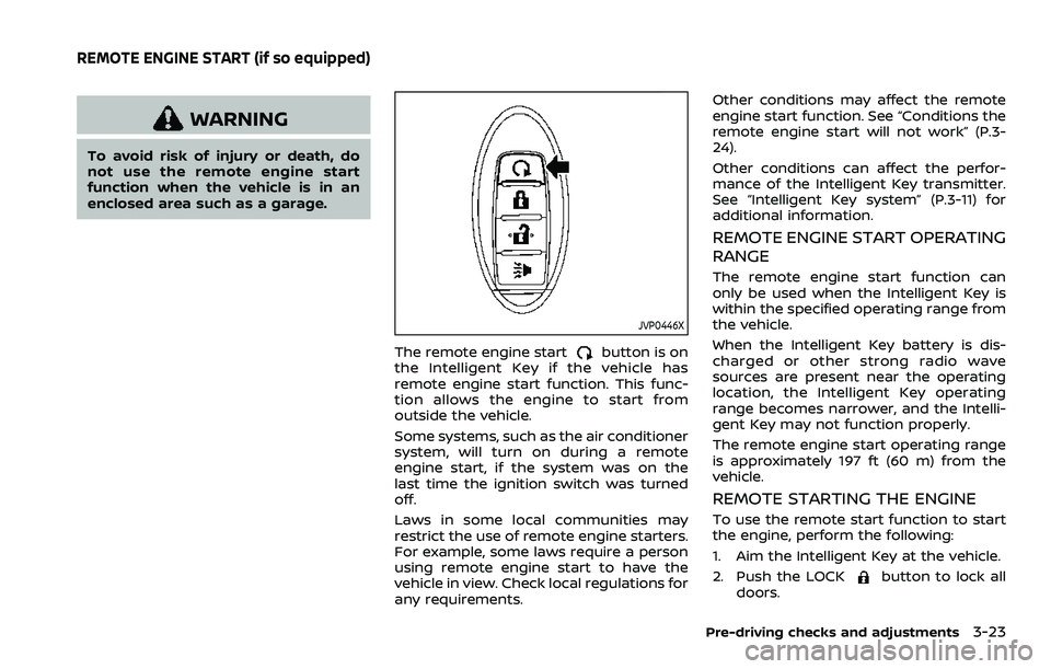
JVP0446X
The remote engine startbutton is on
the Intelligent Key if the vehicle has
remote engine start function. This func-
tion allows the engine to start from
outside the vehicle.
Some systems, such as the air conditioner
system, will turn on during a remote
engine start, if the system was on the
last time the ignition switch was turned
off.
Laws in some local communities may
restrict the use of remote engine starters.
For example, some laws require a person
using remote engine start to have the
vehicle in view. Check local regulations for
any requirements. Other conditions may affect the remote
engine start function. See “Conditions the
remote engine start will not work” (P.3-
24).
Other conditions can affect the perfor-
mance of the Intelligent Key transmitter.
See “Intelligent Key system” (P.3-11) for
additional information.
REMOTE ENGINE START OPERATING
RANGE
The remote engine start function can
only be used when the Intelligent Key is
within the specified operating range from
the vehicle.
When the Intelligent Key battery is dis-
charged or other strong radio wave
sources are present near the operating
location, the Intelligent Key operating
range becomes narrower, and the Intelli-
gent Key may not function properly.
The remote engine start operating range
is approximately 197 ft (60 m) from the
vehicle.
REMOTE STARTING THE ENGINE
To use the remote start function to start
the engine, perform the following:
1. Aim the Intelligent Key at the vehicle.
2. Push the LOCK
button to lock all
doors.
Pre-driving checks and adjustments3-23
REMOTE ENGINE START (if so equipped)
Page 207 of 508
4 Monitor, heater, air conditioner, audioand phone systems
NissanConnect® Owner’s Manual .................................... 4-2
RearView Monitor (if so equipped) ................................. 4-3
RearView Monitor system operation ..................... 4-4
How to read the displayed lines ................................ 4-4
Difference between predictive and
actual distances ...................................................................... 4-4
How to park with predictive course lines .......... 4-6
Adjusting the screen ........................................................... 4-8
How to turn ON and OFF predictive course
lines ........................................................................\
......................... 4-8
RearView Monitor system limitations .................... 4-8
System maintenance .......................................................... 4-9
Intelligent Around View® Monitor (if
so equipped) ........................................................................\
.......... 4-10 Intelligent Around View® Monitor
system operation ................................................................ 4-11
Difference between predictive and
actual distances ................................................................... 4-14
How to park with predictive course lines ....... 4-16
How to switch the display ........................................... 4-17
Adjusting the screen ........................................................ 4-18 Intelligent Around View® Monitor
system limitations ............................................................ 4-18
System maintenance .................................................... 4-20
Moving Object Detection (MOD) (if
so equipped) ........................................................................\
......... 4-21 MOD system operation ................................................ 4-22
Turning MOD on and off ............................................ 4-23
MOD system limitations .............................................. 4-23
System maintenance .................................................... 4-24
Ventilators ........................................................................\
.............. 4-25
Center ventilators ............................................................ 4-25
Side ventilators .................................................................. 4-25
Rear ventilators (if so equipped) .......................... 4-26
Heater and air conditioner ................................................ 4-26 Manual air conditioner and heater .................... 4-27
Automatic air conditioner and heater ............ 4-30
Operating tips (for automatic
air conditioner) ................................................................... 4-33
Servicing air conditioner ............................................. 4-33
Antenna ........................................................................\
.................... 4-33
Car phone or CB radio ......................................................... 4-34
Page 209 of 508
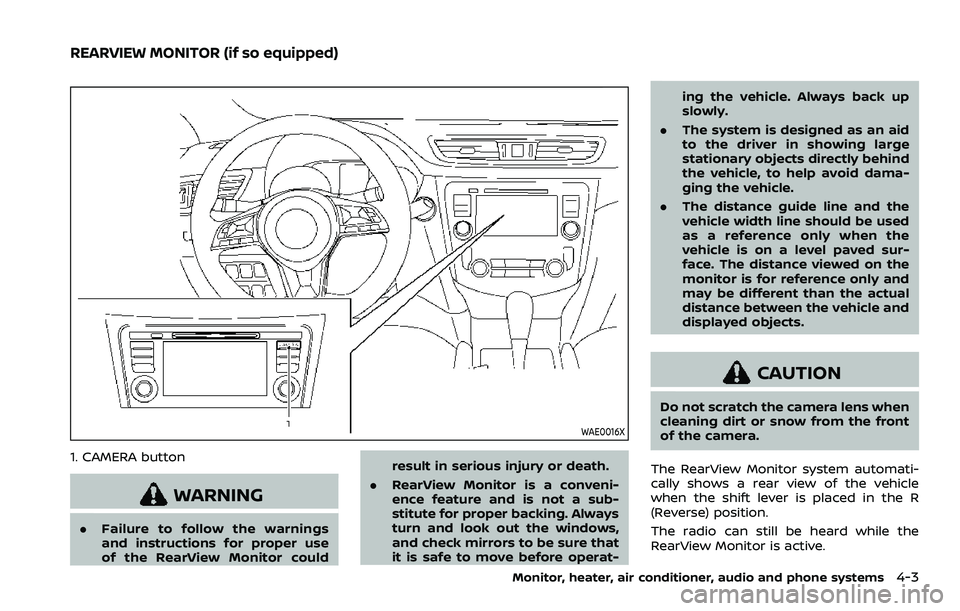
WAE0016X
1. CAMERA button
WARNING
.Failure to follow the warnings
and instructions for proper use
of the RearView Monitor could result in serious injury or death.
. RearView Monitor is a conveni-
ence feature and is not a sub-
stitute for proper backing. Always
turn and look out the windows,
and check mirrors to be sure that
it is safe to move before operat- ing the vehicle. Always back up
slowly.
. The system is designed as an aid
to the driver in showing large
stationary objects directly behind
the vehicle, to help avoid dama-
ging the vehicle.
. The distance guide line and the
vehicle width line should be used
as a reference only when the
vehicle is on a level paved sur-
face. The distance viewed on the
monitor is for reference only and
may be different than the actual
distance between the vehicle and
displayed objects.
CAUTION
Do not scratch the camera lens when
cleaning dirt or snow from the front
of the camera.
The RearView Monitor system automati-
cally shows a rear view of the vehicle
when the shift lever is placed in the R
(Reverse) position.
The radio can still be heard while the
RearView Monitor is active.
Monitor, heater, air conditioner, audio and phone systems4-3
REARVIEW MONITOR (if so equipped)
Page 240 of 508
4-34Monitor, heater, air conditioner, audio and phone systems
— The vehicle is covered with acar cover.
. Be sure that antenna is removed
before the vehicle enters an auto-
matic car wash.
. Always properly tighten the an-
tenna rod during installation.
Otherwise, the antenna rod may
break during vehicle operation.
. A build up of ice on the antenna
can affect radio performance. Re-
move the ice to restore radio
reception.
. When removing snow from the
roof, do not apply strong force to
the antenna. That may cause
broken antenna and roof panel
dent.
. When using a high pressure car
wash, keep the high pressure
nozzle away from the antenna.
The seal may be deformed or
damaged.
. The radio performance may be
affected if cargo carried on the
roof blocks the radio signal. If
possible, do not put cargo near
the antenna.When installing a car phone or a CB radio
in your vehicle, be sure to observe the
following precautions, otherwise the new
equipment may adversely affect the elec-
tronic control modules and electronic
control system harness.
WARNING
.A cellular phone should not be
used for any purpose while driv-
ing so full attention may be given
to vehicle operation. Some juris-
dictions prohibit the use of cellu-
lar phones while driving.
. If you must make a call while your
vehicle is in motion, the hands-
free cellular phone operational
mode (if so equipped) is highly
recommended. Exercise extreme
caution at all times so full atten-
tion may be given to vehicle
operation.
. If a conversation in a moving
vehicle requires you to take
notes, pull off the road to a safe
location and stop your vehicle
before doing so.
CAUTION
.Keep the antenna as far away as
possible from the electronic con-
trol modules.
. Keep the antenna wire more than
8 in (20 cm) away from the
electronic control system har-
ness. Do not route the antenna
wire next to any harness.
. Adjust the antenna standing-
wave ratio as recommended by
the manufacturer.
. Connect the ground wire from the
CB radio chassis to the body.
. For details, it is recommended
you visit a NISSAN dealer.
CAR PHONE OR CB RADIO
Page 247 of 508
recommended you visit a NISSAN
dealer for these services.
. Replacing tires with those not
originally specified by NISSAN
could affect the proper operation
of the TPMS.
. Do not inject any tire liquid or
aerosol tire sealant into the tires,
as this may cause a malfunction
of the tire pressure sensors
(models without emergency tire
puncture repair kit).
. NISSAN recommends using only
Genuine NISSAN Emergency Tire
Sealant provided with your vehi-
cle. Other tire sealants may da-
mage the valve stem seal which
can cause the tire to lose air
pressure. Visit a NISSAN dealer
as soon as possible after using
tire repair sealant (models with
emergency tire puncture repair
kit).
CAUTION
.The TPMS may not function prop-
erly when the wheels are
equipped with tire chains or the
wheels are buried in snow. .
Do not place metalized film or
any metal parts (antenna, etc.) on
the windows. This may cause
poor reception of the signals
from the tire pressure sensors,
and the TPMS will not function
properly.
Some devices and transmitters may tem-
porarily interfere with the operation of
the TPMS and cause the low tire pressure
warning light to illuminate. Some exam-
ples are:
. Facilities or electric devices using
similar radio frequencies are near the
vehicle.
. If a transmitter set to similar frequen-
cies is being used in or near the
vehicle.
. If a computer (or similar equipment) or
a DC/AC converter is being used in or
near the vehicle.
Low tire pressure warning light may
illuminate in the following cases.
. If the vehicle is equipped with a wheel
and tire without TPMS.
. If the TPMS has been replaced and the
ID has not been registered.
. If the wheel is not originally specified
by NISSAN. FCC Notice:
For USA:
This device complies with Part 15 of the
FCC Rules. Operation is subject to the
following two conditions: (1) This device
may not cause harmful interference,
and (2) this device must accept any
interference received, including inter-
ference that may cause undesired op-
eration.
Note: Changes or modifications not
expressly approved by the party re-
sponsible for compliance could void
the user’s authority to operate the
equipment.
For Canada:
This device complies with Industry Ca-
nada licence-exempt RSS standard(s).
Operation is subject to the following
two conditions: (1) this device may not
cause interference, and (2) this device
must accept any interference, including
interference that may cause undesired
operation of the device.
Starting and driving5-7
Page 254 of 508

5-14Starting and driving
KEY POSITIONS
LOCK: Normal parking position (0)
OFF: (Not used) (1)
This position activates electrical acces-
sories such as the radio when the engine
is not running.
ON: Normal operating position (2)
This position turns on the ignition system
and the electrical accessories.
START: (3)
This position starts the engine. As soon as
the engine has started, release the key. It
automatically returns to the ON position.
WARNING
Do not operate the push-button
ignition switch while driving the ve-
hicle except in an emergency. (The
engine will stop when the ignition
switch is pushed 3 consecutive times
or the ignition switch is pushed and
held for more than 2 seconds.) If the
engine stops while the vehicle is
being driven, this could lead to a
crash and serious injury.
Before operating the push-button igni-
tion switch, be sure to move the shift
lever to the P (Park) position (for Con-
tinuously Variable Transmission (CVT)
models) or the shift lever to the N
(Neutral) position (for Manual Transmis-
sion (MT) models).
SSD0436
OPERATING RANGE FOR ENGINE
START FUNCTION
The Intelligent Key can only be used for
starting the engine when the Intelligent
Key is within the specified operating
range
.
When the Intelligent Key battery is almost
discharged or strong radio waves are
present near the operating location, the
Intelligent Key system’s operating range
becomes narrower and may not function
properly.
If the Intelligent Key is within the operat-
ing range, it is possible for anyone, even
someone who does not carry the Intelli-
gent Key, to push the ignition switch to
PUSH-BUTTON IGNITION SWITCH
(model with Intelligent Key system)
Page 256 of 508
5-16Starting and driving
Continuously Variable Transmis-
sion (CVT) models
The ignition lock is designed so that the
ignition switch position cannot be
switched to OFF until the shift lever is
moved to the P (Park) position.
When the ignition switch cannot be
pushed toward the OFF position, proceed
as follows:
1. Move the shift lever into the P (Park)position.
2. Push the ignition switch. The ignition switch position will change to the ON
position.
3. Push the ignition switch again to the OFF position.
The shift lever can be moved from the P
(Park) position if the ignition switch is in
the ON position and the brake pedal is
depressed.
PUSH-BUTTON IGNITION SWITCH
POSITIONS
LOCK (Normal parking position)
The ignition switch can only be locked at
this position.
The ignition switch will lock when any
door is opened or closed with the ignition
switched off.
ON (Normal operating position)
The ignition system and the electrical
accessory power activate at this position
without the engine turned on.
The ON position has a battery saver
feature that will place the ignition switch
in the OFF position, if the vehicle is not
running, after some time under the fol-
lowing conditions:
. all doors are closed.
. shift lever is in P (Park) position (CVT
model) or N (Neutral) position (MT
model).
The battery saver feature will be can-
celled if any of the following occur:
. any door is opened.
. shift lever is moved out of the P (Park)
position (CVT model). .
ignition switch changes position.
OFF position
The engine is turned off in this position.
Auto ACC position
With the vehicle in the P (Park) position
(CVT models) or the N (Neutral) position
(MT models), the Intelligent Key with you
and the ignition placed from ON to OFF,
the radio can still be used for a period of
time, or until the driver’s door is opened.
After a period of time, functions such as
radio, navigation (if so equipped), and
Bluetooth® Hands-Free Phone System
may be restarted by turning on the audio
system (see the separate NissanConnect®
Owner’s Manual), or by pushing the UN-
LOCK button on the Intelligent Key for up
to a total of 30 minutes.
EMERGENCY ENGINE SHUT OFF
To shut off the engine in an emergency
situation while driving, perform the fol-
lowing procedure:
.Rapidly push the push-button ignition
switch 3 consecutive times in less
than 1.5 seconds, or
. Push and hold the push-button igni-
tion switch for more than 2 seconds.
Page 293 of 508

condition may also be caused by objects
such as ice, frost or dirt obstructing the
radar sensors.
NOTE:
If the BSW system stops working, the
RCTA system will also stop working.
Action to take:
When the above conditions no longer
exist, the system will resume automati-
cally.
If the “Unavailable: Side Radar Obstruc-
tion” warning message continues to ap-
pear, have the system checked. It is
recommended that you visit a NISSAN
dealer for this service.
SYSTEM MALFUNCTION
When the BSW system malfunctions, it will
be turned off automatically and the
system malfunction warning message will
appear in the vehicle information display.
NOTE:
If the BSW system stops working, the
RCTA system will also stop working.
Action to take:
Stop the vehicle in a safe location, turn
the engine off and restart the engine. If
the message continues to appear, have
the BSW system checked. It is recom-
mended that you visit a NISSAN dealer for
this service.
JVS0649X
SYSTEM MAINTENANCE
The two radar sensorsfor the BSW
system are located near the rear bumper.
Always keep the area near the radar
sensors clean.
The radar sensors may be blocked by
temporary ambient conditions such as
splashing water, mist or fog.
The blocked condition may also be
caused by objects such as ice, frost or
dirt obstructing the radar sensors.
Check for and remove objects obstruct-
ing the area around the radar sensors.
Do not attach stickers (including trans-
parent material), install accessories or apply additional paint near the radar
sensors.
Do not strike or damage the area around
the radar sensors.
See a NISSAN dealer or other authorized
repair shop if the area around the radar
sensors is damaged due to a collision.
Radio frequency statement
For USA
FCC : OAYSRR3B
This device complies with part 15 of the
FCC Rules. Operation is subject to the
following two conditions:
(1) This device may not cause harmful
interference, and (2) this device must
accept any interference received, in-
cluding interference that may cause
undesired operation.
FCC Warning
Changes or modifications not expressly
approved by the party responsible for
compliance could void the user’s
authority to operate the equipment
For Canada
This device complies with Industry Ca-
nada licence-exempt RSS standard(s).
Operation is subject to the following
two conditions: (1) this device may not
cause interference, and (2) this device
must accept any interference, including
Starting and driving5-53