2023 NISSAN PATHFINDER steering wheel adjustment
[x] Cancel search: steering wheel adjustmentPage 237 of 665

3 Pre-driving checks and adjustments
Keys.............................................3-2NISSAN Intelligent Key® .......................3-2
NISSAN Vehicle Immobilizer System
keys..........................................3-4
Doors ...........................................3-5
Locking with key .............................3-5
Locking with inside lock knob ................3-6
Locking with power door lock switch .........3-6
Automatic door locks ........................3-6
Child safety rear door lock .................... 3-7
NISSAN Intelligent Key® system .................. 3-7
Operating range .............................3-8
Door locks/unlocks precaution ...............3-9
NISSAN Intelligent Key® Operation ............3-9
How to use the remote keyless entry
function ..................................... 3-13
Approach unlock function ...................3-17
Walk away lock function .....................3-17
Warning signals ............................. 3-17
Troubleshooting guide ......................3-18
Remote Engine Start (if so equipped) ...........3-20
Remote Engine Start operating range .......3-20
Remote starting the vehicle .................3-21
Extending engine run time ..................3-21
Canceling a Remote Engine Start ...........3-21
Conditions the Remote Engine Start will
notwork .................................... 3-22Hood
........................................... 3-23
Lif tgate ........................................ 3-23
Operating the manual lif tgate
(if so equipped) .............................. 3-24
Operating the power lif tgate
(if so equipped) .............................. 3-24
Motion-Activated Lif tgate
(if so equipped) .............................. 3-27
Lif tgate release ............................. 3-29
Lif tgate position setting
(if so equipped) .............................. 3-30
Fuel-filler door .................................. 3-31
Opening the fuel-filler door ..................3-31
How to refuel ................................ 3-32
When refueling from a portable fuel
container ................................... 3-33
Steering wheel ................................. 3-34
Manual operation (if so equipped) ...........3-34
Automatic operation (if so equipped) ........3-35
Sun visors ...................................... 3-36
Vanity mirrors ............................... 3-36
C
ard holder ................................. 3-37
Mirrors ......................................... 3-37
Manual anti-glare rearview mirror
(if so equipped) .............................. 3-37
Page 271 of 665

Be sure to insert the funnel into the fuel-
filler opening slowly and fully. Insert the
nozzle of the portable fuel container into
the opening along the funnel and fill the
fuel tank.
Af ter refueling, remove the funnel from the
fuel-filler opening. Wipe the funnel clean
and return it to the tool bag.
CAUTION
• Do not insert the nozzle of the por-
table fuel container directly into the
fuel-filler opening. Doing so may
damage the opening and the fuel
system.
• Use only the funnel provided with
your vehicle. Otherwise the fuel-filler
opening and the fuel system may be
damaged.
WARNING
• Do not adjust the steering wheel
while driving. You could lose control
of your vehicle and cause an
accident.
• Do not adjust the steering wheel any
closer to you than is necessary for
proper steering operation and com-
fort. The driver's air bag inflates with
great force. If you are unrestrained,
leaning forward, sitting sideways or
out of position in any way, you are at
greater risk of injury or death in a
crash. You may also receive serious
or fatal injuries from the air bag if you
are up against it when it inflates. Al-
ways sit back against the seatback
and as far away as practical from the
steering wheel. Always use the seat
belts.
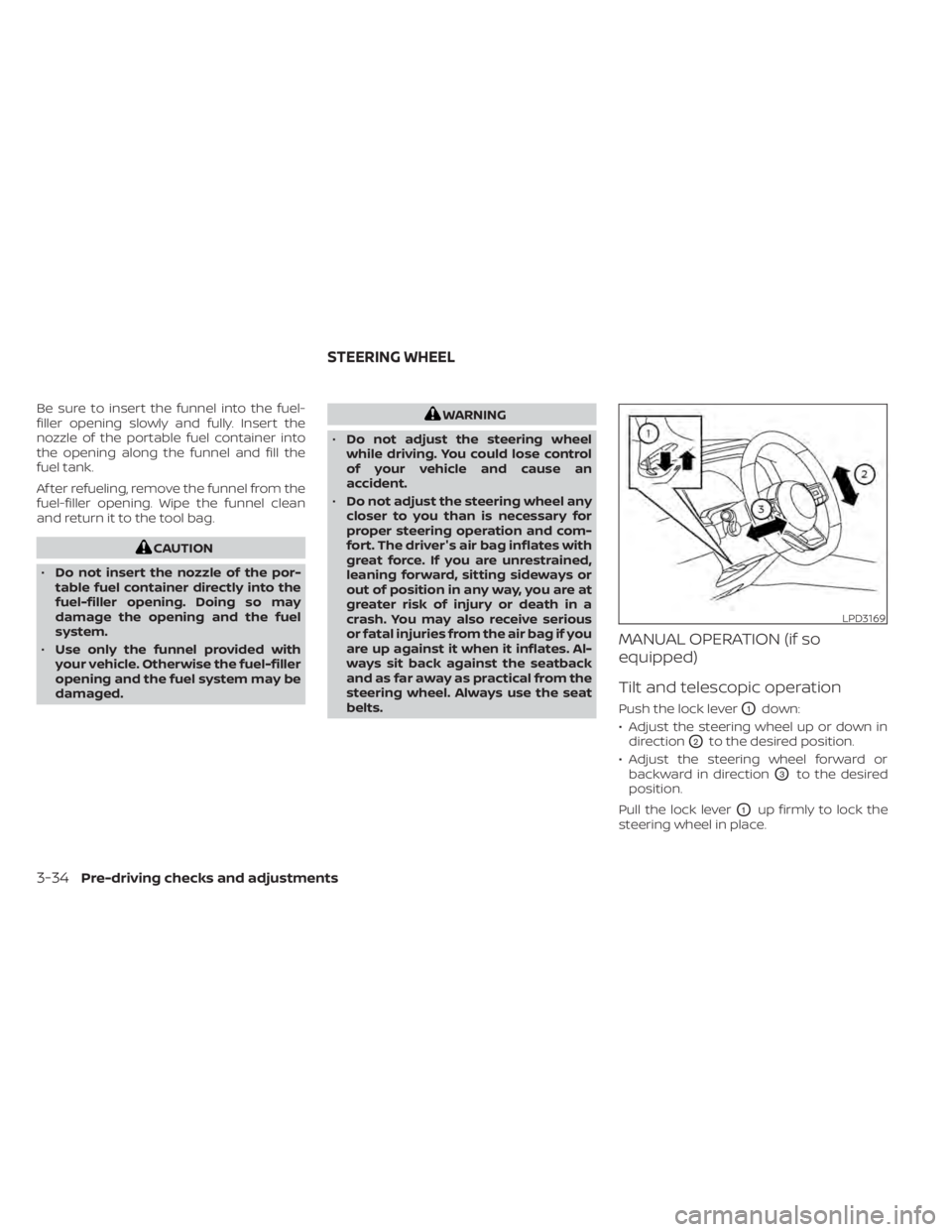
MANUAL OPERATION (if so
equipped)
Tilt and telescopic operation
Push the lock leverO1down:
• Adjust the steering wheel up or down in direction
O2to the desired position.
• Adjust the steering wheel forward or backward in direction
O3to the desired
position.
Pull the lock lever
O1up firmly to lock the
steering wheel in place.
LPD3169
STEERING WHEEL
3-34Pre-driving checks and adjustments
Page 272 of 665

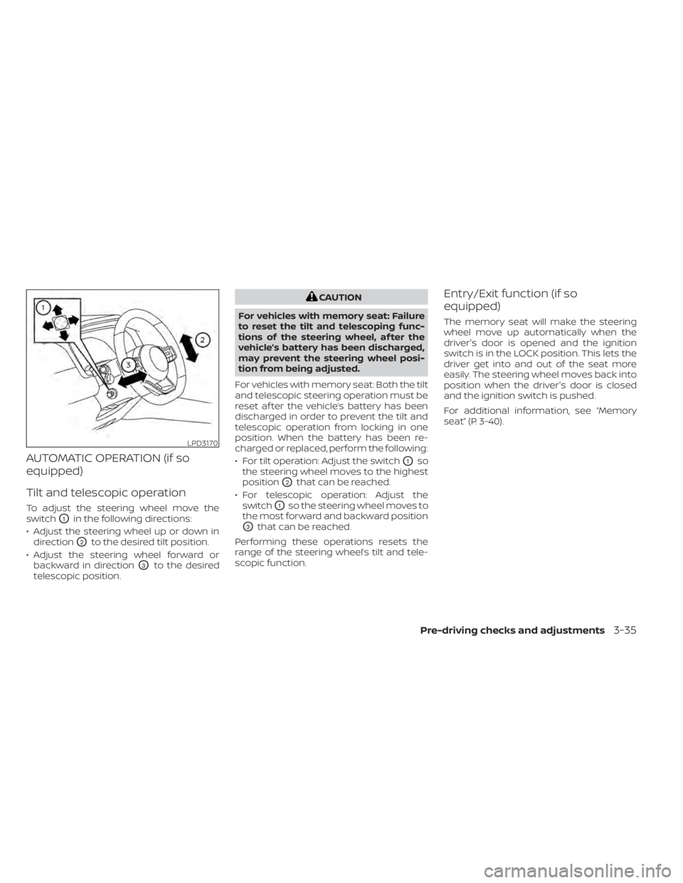
AUTOMATIC OPERATION (if so
equipped)
Tilt and telescopic operation
To adjust the steering wheel move the
switch
O1in the following directions:
• Adjust the steering wheel up or down in direction
O2to the desired tilt position.
• Adjust the steering wheel forward or backward in direction
O3to the desired
telescopic position.
CAUTION
For vehicles with memory seat: Failure
to reset the tilt and telescoping func-
tions of the steering wheel, af ter the
vehicle’s battery has been discharged,
may prevent the steering wheel posi-
tion from being adjusted.
For vehicles with memory seat: Both the tilt
and telescopic steering operation must be
reset af ter the vehicle’s battery has been
discharged in order to prevent the tilt and
telescopic operation from locking in one
position. When the battery has been re-
charged or replaced, perform the following:
• For tilt operation: Adjust the switch
O1so
the steering wheel moves to the highest
position
O2that can be reached.
• For telescopic operation: Adjust the switch
O1so the steering wheel moves to
the most forward and backward position
O3that can be reached.
Performing these operations resets the
range of the steering wheel’s tilt and tele-
scopic function.
Entry/Exit function (if so
equipped)
The memory seat will make the steering
wheel move up automatically when the
driver's door is opened and the ignition
switch is in the LOCK position. This lets the
driver get into and out of the seat more
easily. The steering wheel moves back into
position when the driver's door is closed
and the ignition switch is pushed.
For additional information, see “Memory
seat” (P. 3-40).
LPD3170
Pre-driving checks and adjustments3-35
Page 278 of 665

5. Within the settings menu of the touchscreen display, select “Edit User” and
then “User Profiles”.
6. Create a personal profile and make sure the correct key number is selected with
the arrow.
7. Set the desired seat, steering and mirror positions.
8. Place the ignition switch in the OFF po- sition and lock the vehicle with the Intel-
ligent Key.
Once Step 8 is completed, every time the
vehicle is unlocked using the Intelligent Key
and the ignition is switched placed in the
ON position, the memory positions will be
recalled.
For additional information, see the
“NissanConnect® Owner’s Manual.
Follow the same procedure if you want
to link the 2nd, 3rd or 4th Intelligent Key.
NOTE:
If new memory positions are set prior to
turning the ignition from ON to OFF, the
previously linked memory positions for
the respective key will be overwritten by
new positions.
Recalling Intelligent Key memory
positions
If the “Key-Linked Settings” are enabled in
the vehicle information display for that par-
ticular key, every time you enter the vehicle
the driver’s seat, automatic steering wheel,
and outside mirrors will automatically
move to the driver’s last position of the
respective Intelligent Key.
NOTE:
The key-linked memory positions can be
different from the positions stored in the
memory switch (1 or 2).
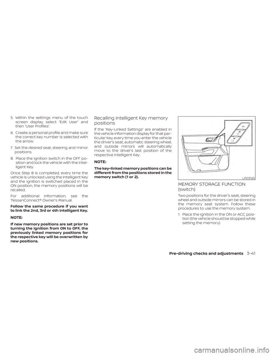
MEMORY STORAGE FUNCTION
(switch)
Two positions for the driver's seat, steering
wheel and outside mirrors can be stored in
the memory seat system. Follow these
procedures to use the memory system.
1. Place the ignition in the ON or ACC posi- tion (the vehicle should be stopped while
setting the memory).
LPD3165
Pre-driving checks and adjustments3-41
Page 279 of 665

2. Adjust the driver's seat, steering wheeland outside mirrors to the desired posi-
tions by manually operating each ad-
justing switch. For additional informa-
tion, see “Seats” (P. 1-2), “Steering wheel”
(P. 3-34) and “Outside mirrors” (P. 3-38).
3. Push the SET switch and, within 5 sec- onds, push the memory switch (1 or 2).
4. The indicator light for the pushed memory switch will come on and stay
on for approximately 5 seconds.
5. The chime will sound if the memory has been stored.
NOTE:
If a new memory position is stored in the
same memory switch, the previous
memory position will be overwritten by
the new stored position.
Linking a key fob to a stored
memory position
Each key fob can be linked to a stored
memory position (memory switch 1 or 2)
with the following procedure.
1. Follow steps 1-3 in the “Memory storagefunction” section for storing the memory
position. 2. The indicator light for the pushed
memory switch will come on. While the
indicator light is on for 5 seconds, press
the
button on the key fob. The haz-
ard lights will flash once and memory
switch will click twice. Af ter the indictor
light goes off, the key fob is linked to that
memory setting.
Once it is linked, when the ignition switch is
in the OFF position, pressing the
but-
ton on the key fob will move the driver’s
seat, steering wheel and outside mirrors to
the linked memory switch position.
NOTE:
If a new memory position is stored in the
linked memory switch, then the key fob
will link the new position and overwrites
the previous position.
Confirming memory storage
• Push the SET switch.
• If a memory position has been stored in the switch (1 or 2) then the indicator light
for the respective switch will stay on for
approximately 5 seconds.
ENTRY/EXIT FUNCTION
This system is designed so that the driver's
seat and steering wheel will automatically
move when the shif t position is in the P
(Park) position. This allows the driver to
easily get in and out of the driver’s seat.
The driver’s seat will slide backward and
the steering wheel will move up:
• When the driver’s door is opened with theignition switch in the OFF position.
• When the ignition switch is changed from ACC to OFF with the driver’s door open.
The driver’s seat and steering wheel will
return to the previous position:
• When the ignition switch is changed from ACC or ON while the shif t position is in the
P (Park) position.
The entry/exit function can be adjusted or
canceled through “Vehicle Settings” in the
vehicle information display by performing
the following:
• Switch the Exit Seat Slide from on to off.
• Switch the Exit Steering UP from on to off.
3-42Pre-driving checks and adjustments
Page 280 of 665

Restarting the entry/exit function
If the battery cable is disconnected or if the
fuse opens, the stored memory positions
may be lost and some of the functions will
be restricted.
1. Drive the vehicle over 25 mph (40 km/h).
OR
2. Open and close the driver's door morethan two times with the ignition switch
in the OFF position.
The entry/exit function should now work
properly.
SETTING MEMORY FUNCTION
The position of the following settings can
be linked to the Intelligent Key and the
memorized settings can be available for
each Intelligent Key.
• Climate control system
• Audio system
To use the memory function, set the cli-
mate and audio systems to the driver's
preferred settings. Lock the doors with the
Intelligent Key. Each Intelligent Key may be
set with the driver's individual preferences.
When a new Intelligent Key is used, “Con-
nection with the key has been done” will be displayed on the vehicle information dis-
play and the memorized settings are
available.
To engage the memorized settings, per-
form the following:
1. Carry the Intelligent Key that is linked to
the memorized settings.
2. Unlock the doors by wrapping hand around the capacitive door handle or
the
button on the Intelligent Key.
3. Place the ignition switch in the ON posi- tion. The settings linked to the Intelligent
Key will start.
For additional information on using the cli-
mate control system, see “Heater and air
conditioner (automatic)” (P. 4-32).
SYSTEM OPERATION
The memory seat system will not work or
will stop operating under the following
conditions:
• When the vehicle speed is above 4 mph (7 km/h).
• When any of the memory switches are pushed while the memory seat is
operating. • When the switch for the driver’s seat and
steering wheel is pushed while the
memory seat is operating.
• When the seat has already been moved to the memorized position.
• When no seat position is stored in the memory switch.
• When the shif t position is moved from P (Park) position to any other position.
Pre-driving checks and adjustments3-43
Page 593 of 665

Parking brake:Check the parking brake
operation regularly. The vehicle should be
securely held on a fairly steep hill with only
the parking brake applied. If the parking
brake needs adjustment, it is recom-
mended that you visit a NISSAN dealer for
this service.
Seats: Check seat position controls such
as seat adjusters, seatback recliner, etc., to
ensure they operate smoothly and all
latches lock securely in every position.
Check that the head restraints/headrests
move up and down smoothly and the locks
(if so equipped) hold securely in all latched
positions.
Seat belts: Check that all parts of the seat
belt system (for example, buckles, anchors,
adjusters and retractors) operate properly
and smoothly, and are installed securely.
Check the belt webbing for cuts, fraying,
wear or damage.
Steering wheel: Check for changes in the
steering system, such as excessive free
play, hard steering or strange noises.
Transmission P (Park) position mecha-
nism: On a fairly steep hill check that the
vehicle is held securely with the shif t posi-
tion in the P (Park) position without apply-
ing any brakes. Warning lights and chimes:
Make sure all
warning lights and chimes are operating
properly.
Windshield defroster: Check that the air
comes out of the defroster outlets properly
and in sufficient quantity when operating
the heater or air conditioner.
Windshield wiper and washer*: Check
that the wipers and washer operate prop-
erly and that the wipers do not streak.
Under the hood and vehicle
The maintenance items listed here should
be checked periodically (for example, each
time you check the engine oil or refuel).
Battery* (for maintenance free batter-
ies): This vehicle is equipped with a sealed
maintenance free battery. It is recom-
mended that you visit a NISSAN dealer for
service.
NOTE:
Care should be taken to avoid situations
that can lead to potential battery dis-
charge and potential no-start conditions
such as:
1. Installation or extended use of elec- tronic accessories that consume bat-
tery power when the engine is not
running (Phone chargers, GPS, DVD
players, etc.).
2. Vehicle is not driven regularly and/or only driven short distances.
In these cases, the battery may need to
be charged to maintain battery health.
Brake fluid level*: Make sure that the brake
fluid level is between the MAX and MIN lines
on the reservoir.
Engine coolant level*: Check the coolant
level when the engine is cold.
Engine drive belts*: Make sure the drive
belts are not frayed, worn, cracked or oily.
Engine oil level*: Check the level af ter
parking the vehicle on a level spot and
turning off the engine. Wait more than 15
minutes for the oil to drain back into the oil
pan.
9-4Maintenance and schedules
Page 655 of 665

Front power seat adjustment.......1-4Rear seat adjustment............1-6Seat beltChild safety................ .1-30Infants and small children........1-31Injured person................1-23Larger children...............1-31Precautions on seat belt usage.....1-20Pregnant women..............1-23Rear center seat belt...........1-26Seat belt extenders............1-29Seat belt maintenance..........1-30Seat belts................1-20,7-6Three-point type with retractor.....1-24Seat belt extenders..............1-29Seat belt warning light.........1-23,2-16Seatback pockets..............2-108Seats
Adjustment..................1-2Armrests...................1-10Front seats..................1-2Heated seats................2-90Manual front seat adjustment......1-3Security system (NISSAN Vehicle Immobilizer
System), engine start..........2-77,5-16Security systemsVehicle security system..........2-76Self-adjusting brakes.............8-20Service manual order form........10-38Servicing air conditioner...........4-39Spark plug replacement...........8-16Spark plugs...................8-16Specifications................ .10-9Speedometer...............2-6, 2-7
Spotlights (See map light).........2-123SRS warning label...............1-80Standard maintenance............9-9Starting
Before starting the engine........5-16Jump starting.............6-11,8-14Precautions when starting and driving.5-4Push starting................6-13Starting the engine............5-16Starting the engine..............5-16SteeringPower steering system.........5-174Steering Assist switch (for vehicles
with ProPILOT Assist).............2-95Steering wheel................ .3-34Stop light....................8-26Storage.....................2-107Storage tray..................2-109Sun visors................... .3-36Sunglasses case...............2-111Sunglasses holder..............2-111Sunroof..................2-121, 7-5Supplemental air bag warning labels. . .1-80Supplemental air bag warning
light................... .1-80, 2-16Supplemental front impact air bag
system..................... .1-67Supplemental restraint system
Information and warning labels. . . .1-80Precautions on supplemental restraint
system................... .1-59Supplemental restraint system (Supplemen-
tal air bag system)..............1-59Switch Autolight switch
..............2-83Automatic power window switch. . .2-119Fog light switch..............2-89Hazard warning flasher switch......6-2Headlight and turn signal switch. . . .2-82Headlight control switch.........2-82Hill descent control switch........2-94Instrument brightness control.....2-88Power door lock switch..........3-6Rear window and outside mirror defroster
switch...................
.2-81Rear window wiper and washer
switches...................2-80Turn signal switch.............2-88
T
Tachometer...................2-8Temperature gauge
Engine coolant temperature gauge. . .2-9Thef t (NISSAN Vehicle Immobilizer System),
engine start...............2-77,5-16Three-way catalyst...............5-4TireFlat tire................. .6-3, 6-4Spare tire...............6-5, 8-42Tire and Loading Information label. .10-13Tire chains.................8-38Tire pressure................8-28Tire rotation.................8-39Tires of 4-wheel drive...........8-41Types of tires................8-37Uniform tire quality grading......10-33
11-6