Page 13 of 346
1. Headlight/turn signal switch(P. 2-18)
2. Driver’s supplemental air bag
(P. 1-44)
Horn (P. 2-21)
3. Meters and gauges (P. 2-3)
4. Wiper and washer switch (P. 2-16)
5. Center vents (P. 4-13)
6. Rear window and outside mirror
(if so equipped) defroster switch
(P. 2-18)
7. Hazard warning flasher switch
(P. 6-2)
8. Front passenger air bag status
light (P. 1-44)
9. Climate controls (P. 4-14, 4-20)
10. Audio system (P. 4-28) AUX IN jack (P. 4-32)
11. Passenger’s supplemental air bag
(P. 1-44)
12. Side vents (P. 4-13)
13. Glove box (P. 2-23)
14. Shif t lever (P. 5-9)
15. Cup holders (P. 2-23)
16. 12v power outlet (P. 2-22)
17. USB port (P. 4-37)
18. Cruise control (if so equipped)
(P. 5-17)
19. Ignition switch (P. 5-5)
LII2632
INSTRUMENT PANEL
0-6Illustrated table of contents
Page 14 of 346
20. Tilt steering (P. 3-13)
21. Audio control switches(if so equipped) (P. 4-47)
Bluetooth® hands-free phone
system controls (if so equipped)
(P. 4-51)
22. Fuel-filler door release lever (P. 3-11) Hood release lever (P. 3-9)
23. Vehicle Dynamic Control (VDC) OFF
switch (P. 2-22)
24. Electronic outside rearview mirror
control switch (if so equipped)
(P. 3-16)
Refer to the page number indicated in
parentheses for operating details.
Illustrated table of contents0-7
Page 82 of 346

2 Instruments and controls
Instrument panel................................2-2
Meters and gauges ..............................2-3
Speedometer and odometer .................2-4
Tachometer ..................................2-5
Fuel gauge ...................................2-6
Trip computer ................................2-6
Warning lights, indicator lights and audible
reminders .......................................2-8
Checking lights ...............................2-8
Warning lights ................................2-9
Indicator lights ............................... 2-11
Audible reminders ........................... 2-14
Security systems ............................... 2-14
NISSAN Vehicle Immobilizer System .........2-14
Wiper and washer switch .......................2-16
Switch operation ............................ 2-16
Rear switch operation ....................... 2-17
Rear window and outside mirror
(if so equipped) defroster switch ................2-18
Headlight and turn signal switch ...............2-18Headlight control switch
.....................2-18
Daytime Running Lights (DRL) system .......2-19
Instrument brightness control ...............2-20
Turn signal switch ........................... 2-20
Front fog lights (if so equipped) ..............2-21
Horn ........................................... 2-21
Vehicle Dynamic Control (VDC) OFF switch ......2-22
Power outlet .................................... 2-22
Storage ........................................ 2-23
Front-door pockets .......................... 2-23
Storagetray................................. 2-23
Glovebox.................................... 2-24
Cup holders ................................. 2-24
Cargo cover (if so equipped) .................2-25
Windows ....................................... 2-27
Manual windows (if so equipped) ............2-27
Power windows (if so equipped) .............2-27
Interior light .................................... 2-29
Luggage compartment light ...................2-30
Page 83 of 346
1. Headlight/turn signal switch(P. 2-18)
2. Driver’s supplemental air bag
(P. 1-44)
Horn (P. 2-21)
3. Meters and gauges (P. 2-3)
4. Wiper and washer switch (P. 2-16)
5. Center vents (P. 4-13)
6. Rear window and outside mirror
(if so equipped) defroster switch
(P. 2-18)
7. Hazard warning flasher switch
(P. 6-2)
8. Front passenger air bag status
light (P. 1-44)
9. Climate controls (P. 4-14, 4-20)
10. Audio system (P. 4-28) AUX IN jack (P. 4-32)
11. Passenger’s supplemental air bag
(P. 1-44)
12. Side vents (P. 4-13)
13. Glove box (P. 2-23)
14. Shif t lever (P. 5-9)
15. Cup holders (P. 2-23)
16. 12v power outlet (P. 2-22)
17. USB port (P. 4-37)
18. Cruise control (if so equipped)
(P. 5-17)
19. Ignition switch (P. 5-5)
LII2632
INSTRUMENT PANEL
2-2Instruments and controls
Page 84 of 346
20. Tilt steering (P. 3-13)
21. Audio control switches(if so equipped) (P. 4-47)
Bluetooth® hands-free phone
system controls (if so equipped)
(P. 4-51)
22. Fuel-filler door release lever (P. 3-11) Hood release lever (P. 3-9)
23. Vehicle Dynamic Control (VDC) OFF
switch (P. 2-22)
24. Electronic outside rearview mirror
control switch (if so equipped)
(P. 3-16)
Refer to the page number indicated in
parentheses for operating details.
1. Tachometer
2. Speedometer
3. OdometerTrip computer 4. Instrument brightness control
knob
5. Change/reset button
LIC3356
METERS AND GAUGES
Instruments and controls2-3
Page 99 of 346

∙ Pre-mix windshield-washer fluid con-centrates with water to the manufac-
turer’s recommended levels before
pouring the fluid into the windshield-
washer fluid reservoir. Do not use the
windshield-washer fluid reservoir to
mix the windshield-washer fluid con-
centrate and water.
To defrost the rear window glass and out-
side mirrors (if so equipped), start the en-
gine and push the rear window defroster
switch on. The rear window defroster indi-
cator light on the switch comes on. Push
the switch again to turn the defroster off.
The rear window defroster automatically
turns off af ter approximately 15 minutes.
CAUTION
When cleaning the inner side of the rear
window, be careful not to scratch or
damage the rear window defroster.
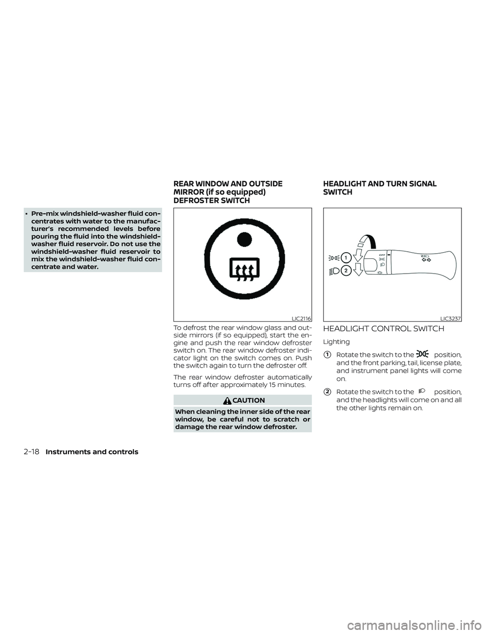
HEADLIGHT CONTROL SWITCH
Lighting
�1Rotate the switch to theposition,
and the front parking, tail, license plate,
and instrument panel lights will come
on.
�2Rotate the switch to theposition,
and the headlights will come on and all
the other lights remain on.
LIC2116LIC3237
REAR WINDOW AND OUTSIDE
MIRROR (if so equipped)
DEFROSTER SWITCH HEADLIGHT AND TURN SIGNAL
SWITCH
2-18Instruments and controls
Page 128 of 346
Manual folding outside mirrors
Pull the outside mirror toward the door to
fold it.
Heated mirrors (if so equipped)
The outside mirrors can be heated to de-
frost, defog, or de-ice for improved visibility.
For additional information, refer to “Rear
window and outside mirror (if so equipped)
defroster switch” in the “Instruments and
controls” section of this manual.
WPD0056
Pre-driving checks and adjustments3-17
Page 145 of 346

Rear window defroster switch
For additional information about the rear
window defroster switch, refer to “Rear win-
dow and outside mirror (if so equipped)
defroster switch” in the “Instruments and
controls” section of this manual.
HEATER OPERATION
Heating
This mode is used to direct heated air to
the foot outlets. Some air also flows from
the defrost outlets.1. Move the air intake lever to the
position for normal heating.
2. Turn the air flow control dial to the
position.
3. Turn the
fan control dial to the
desired position.
4. Turn the temperature control dial to the desired position between the
middle and the hot position.
Ventilation
This mode directs outside air to the side
and center vents.
1. Move the air intake lever to the
position. 2. Turn the air flow control dial to
the
position.
3. Turn the
fan control dial to the
desired position.
4. Turn the temperature control dial to the desired position.
Defrosting or defogging
This mode directs the air to the defrost
outlets to defrost/defog the windows.
1. Move the air intake lever to the
position.
2. Turn the air flow control dial to the
position.
3. Turn the
fan control dial to the
desired position.
4. Turn the temperature control dial to the desired position between the
middle and the hot position.
5. Align lef t and right vents to direct air flow toward the front side windows.
∙ To quickly remove ice or fog from the windows, turn the fan control dial to the
maximum position and the tempera-
ture control dial to the full hot position.
Bi-level heating
This mode directs cooler air from the side
and center vents and warmer air from the
floor outlets. When the temperature con-
trol dial is moved to the full hot or full cool
position, the air between the vents and the
floor outlets is the same temperature.
1. Move the air intake lever to the
position.
2. Turn the air flow control dial to the
position.
3. Turn the
fan control dial to the
desired position.
4. Turn the temperature control dial to the desired position.
Heating and defogging
This mode heats the cabin and defogs the
windshield.
1. Move the air intake lever to the
position.
2. Turn the air flow control dial to the
position.
3. Turn the
fan control dial to the
desired position.
4-16Heater, air conditioner, audio and phone systems