2023 NISSAN ARMADA service indicator
[x] Cancel search: service indicatorPage 126 of 604
2-32Instruments and controls
21. Vehicle ahead detection indica-
tor
This indicator shows the status of the
following systems, if the vehicle is
equipped with them.
.Automatic Emergency Braking (AEB)
with pedestrian detection system
. Intelligent Forward Collision Warning
(I-FCW)
For more details, see “Automatic Emer-
gency Braking (AEB) with pedestrian de-
tection system” (P.5-96) or “Intelligent
Forward Collision Warning (I-FCW)” (P.5-
106).
The figure and color of these indicators
will change depending on the conditions
of the above systems.
22. LDW indicator
This indicator shows the status of the
following systems, if the vehicle is
equipped with them.
. Lane Departure Warning (LDW)
. Intelligent Lane Intervention (I-LI)
For more details, see “Lane Departure
Warning (LDW)” (P.5-26) or “Intelligent
Lane Intervention (I-LI)” (P.5-31).
The figure and color of these indicators
will change depending on the conditions
of the above systems.
23. BSW indicator
This indicator shows the status of the
following systems, if the vehicle is
equipped with them.
. Blind Spot Warning (BSW)
. Intelligent Blind Spot Intervention (I-
BSI)
For more details, see “Blind Spot Warning
(BSW)” (P.5-38) or “Intelligent Blind Spot
Intervention (I-BSI)” (P.5-46).
The figure and color of these indicators
will change depending on the conditions
of the above systems.
24. Malfunction
This warning appears when one or more
of the following systems (if so equipped)
is not functioning properly:
. Automatic Emergency Braking (AEB)
with pedestrian detection system
. Intelligent Forward Collision Warning
(I-FCW)
. Lane Departure Warning (LDW)
. Intelligent Lane Intervention (I-LI)
. Blind Spot Warning (BSW)
. Intelligent Blind Spot Intervention (I-
BSI)
. Intelligent Back-up Intervention (I-BI)
. Rear Cross Traffic Alert (RCTA)
If one or more of these warning appears, have the system checked. It is recom-
mended you visit a NISSAN dealer for this
service.
25. Wiper Mode Guidance
This indicator shows the wiper and
washer switch position.
The selected position is illuminated in
orange when the wiper switch position
is changed.
26. Lights Mode Guidance
This indicator shows the headlight switch
position.
The selected position is illuminated in
orange when the headlight switch posi-
tion is changed. (The display of the light
position varies depending on the models.)
27. Intelligent Cruise Control (ICC)
indicators
These indicators show the Intelligent
Cruise Control (ICC) system status. For
additional information, refer to “Intelligent
Cruise Control (ICC)” (P.5-74).
Page 127 of 604

28. Stop vehicle and Apply parking
brake (if so equipped)
This warning may appear when the
battery charge is low.
Park the vehicle as soon as possible. It is
recommended that you visit a NISSAN
dealer.
29. Cruise indicator
This indicator shows the conventional
(fixed speed) cruise control mode status.
The status is shown by the color.
See “Conventional (fixed speed) cruise
control mode display and indicators”
(P.5-93) for details.
30. Not Available: High Camera
Temp (if so equipped)
This message appears when the Lane
Departure Warning (LDW)/Intelligent Lane
Intervention (I-LI)/Intelligent Blind Spot
Intervention (I-BSI) systems become un-
available because a camera detects an
interior temperature of more than 104°F
(40°C).
For additional information, refer to “Lane
Departure Warning (LDW)” (P.5-26), “Intel-
ligent Lane Intervention (I-LI)” (P.5-31) or
“Intelligent Blind Spot Intervention (I-BSI)”
(P.5-46).
31. Unavailable High Cabin Tem-
perature (if so equipped)
This warning appears if the interior tem-
perature of the vehicle has reached such
a high temperature that the sensor for
the Traffic Sign Recognition (TSR) system
can no longer function reliably.
Once the interior temperature has
reached normal levels, the warning
should disappear.
If the warning continues to display, have
the system checked. It is recommended
that you visit a NISSAN dealer for this
service.
For additional information, refer to “Traffic
Sign Recognition (TSR)” (P.5-23).
32. Unavailable Side Radar Ob-
struction (if so equipped)
This message appears when the Blind
Spot Warning (BSW)/Intelligent Blind Spot
Intervention (I-BSI)/Rear Cross Traffic
Alert (RCTA)/Intelligent Back-up Interven-
tion (I-BI) systems become unavailable
because a radar blockage is detected.
For additional information, refer to “Blind
Spot Warning (BSW)” (P.5-38), “Intelligent
Blind Spot Intervention (I-BSI)” (P.5-46),
“Rear Cross Traffic Alert (RCTA)” (P.5-57)
or “Intelligent Back-up Intervention (I-BI)”
(P.5-63).
33. Unavailable: High Accelerator
Temperature
This message appears when the Intelli-
gent Back-up Intervention (I-BI) system
becomes unavailable because of an inter-
ior temperature greater than approxi-
mately 104°F (40°C). For additional
information, refer to “Intelligent Back-up
Intervention (I-BI)” (P.5-63).
34. Forward Driving Aids tempora-
rily disabled Front Sensor blocked
warning
This message appears when the sensor
area of the front bumper is covered with
dirt or is obstructed, making it impossible
to detect a vehicle ahead.
The following systems will be automati-
cally canceled.
.Intelligent Cruise Control (ICC) system
(if so equipped)
. Automatic Emergency Braking (AEB)
with pedestrian detection system
. Intelligent Forward Collision Warning
(I-FCW)
For more details, see “Intelligent Cruise
Control (ICC)” (P.5-74), “Automatic Emer-
gency Braking (AEB) with pedestrian de-
tection system” (P.5-96) or “Intelligent
Forward Collision Warning (I-FCW)” (P.5-
106).
Instruments and controls2-33
Page 135 of 604
.Unlocking the door or opening the
liftgate without using the button on
the Intelligent Key, the door handle
request switch or the mechanical key.
(Even if the door is opened by releas-
ing the door inside lock knob, the
alarm will activate.)
. Opening the hood.
How to stop an activated alarm
The alarm will stop when a door is
unlocked by pushing the unlock button
on the Intelligent Key, the door handle
request switch or using the mechanical
key, or when the ignition switch is pushed
to the ACC or ON position.
If the system does not operate as
described above, it is recommended
you have it checked by a NISSAN dealer.
NISSAN VEHICLE IMMOBILIZER SYS-
TEM
The NISSAN Vehicle Immobilizer System
will not allow the engine to start without
the use of the registered Intelligent Key.
Never leave these keys in the vehicle.
FCC Notice:
For USA:
This device complies with Part 15 of the
FCC Rules. Operation is subject to the
following two conditions: (1) This device
may not cause harmful interference, and (2) this device must accept any
interference received, including inter-
ference that may cause undesired op-
eration.
NOTE:
Changes or modifications not expressly
approved by the party responsible for
compliance could void the user’s
authority to operate the equipment.
For Canada:
This device complies with Industry Ca-
nada licence-exempt RSS standard(s).
Operation is subject to the following
two conditions: (1) this device may not
cause interference, and (2) this device
must accept any interference, including
interference that may cause undesired
operation of the device.
SIC2045
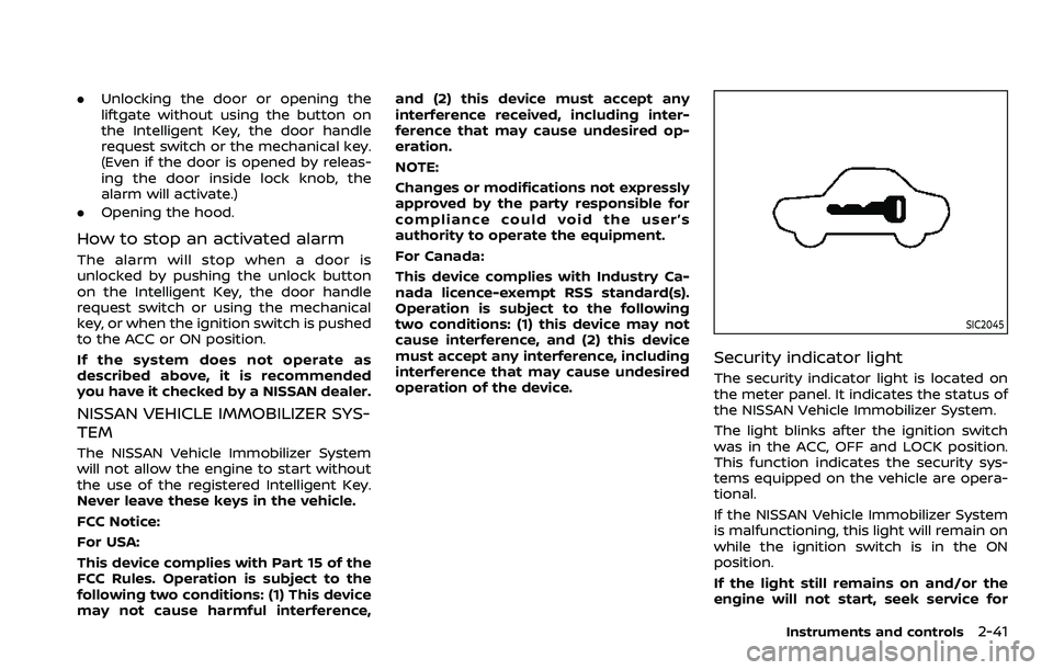
Security indicator light
The security indicator light is located on
the meter panel. It indicates the status of
the NISSAN Vehicle Immobilizer System.
The light blinks after the ignition switch
was in the ACC, OFF and LOCK position.
This function indicates the security sys-
tems equipped on the vehicle are opera-
tional.
If the NISSAN Vehicle Immobilizer System
is malfunctioning, this light will remain on
while the ignition switch is in the ON
position.
If the light still remains on and/or the
engine will not start, seek service for
Instruments and controls2-41
Page 150 of 604
2-56Instruments and controls
.Any liquid spilled on the heated
seat should be removed immedi-
ately with a dry cloth.
. When cleaning the seat, never use
gasoline, thinner, or any similar
materials.
. If any malfunctions are found or
the heated seat does not operate,
turn the switch off and have the
system checked. It is recom-
mended you visit a NISSAN dealer
for this service.
WAC0524X
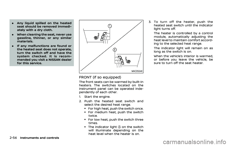
FRONT (if so equipped)
The front seats can be warmed by built-in
heaters. The switches located on the
instrument panel can be operated inde-
pendently of each other.
1. Start the engine.
2. Push the heated seat switch and
select the desired heat range.
.For high heat, push the switch once..For medium heat, push the switch
twice.
.For low heat, push the switch threetimes.
.The indicator lighton the switch
will illuminate depending on the
heat level when the heater is on. 3. To turn off the heater, push the
heated seat switch until the indicator
light turns off.
The heater is controlled by a control
module, automatically adjusting the
heat level to maintain comfort accord-
ing to the selected heat range.
The indicator light will remain on as
long as the switch is on.
When the vehicle’s interior is warmed,
or before you leave the vehicle, be
sure to turn off the seat heater.
Page 152 of 604
2-58Instruments and controls
4. When the vehicle’s interior is warmedor cooled, or before you leave the
vehicle, be sure to turn off the climate
controlled seats. To turn off the cli-
mate controlled seats, push the
switch until the indicator light turns
off.
To check the air filters for the climate
controlled seat, it is recommended
you visit a NISSAN dealer.
WARNING
Do not use or allow occupants to use
the climate controlled seats if you or
the occupants cannot monitor seat
temperatures or have an inability to
feel pain in those body parts in
contact with the seat. Use of the
climate controlled seats by such
people could result in serious injury.
CAUTION
.The battery could run down if the
climate controlled seat is oper-
ated while the engine is not run-
ning. .
Do not use the climate controlled
seat for extended periods or
when no one is using the seat.
. Do not put anything on the seat
which insulates heat, such as a
blanket, cushion, seat cover, etc.
Otherwise, the seat may become
overheated.
. Do not place anything hard or
heavy on the seat or pierce it with
a pin or similar object. This may
result in damage to the climate
controlled seat.
. Any liquid spilled on the seat
should be removed immediately
with a dry cloth.
. The climate controlled seat has
an air filter. Do not operate cli-
mate controlled seat without an
air filter. This may result in da-
mage to the system.
. When cleaning the seat, never use
gasoline, thinner, or any similar
materials.
. If any malfunctions are found or
the climate controlled seat does
not operate, turn the switch off
and have the system checked. It
is recommended you visit a
NISSAN dealer for this service.
SSD0956
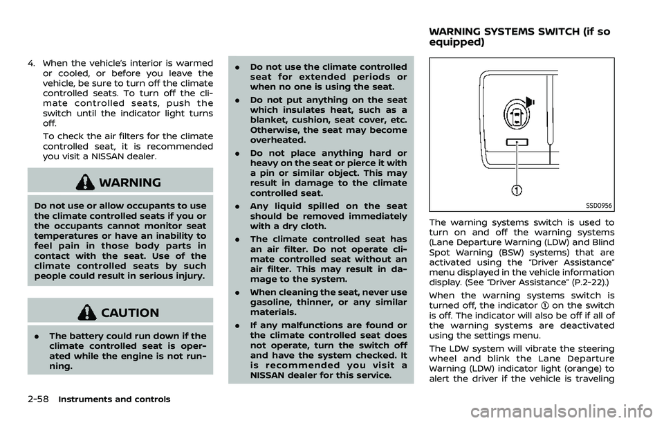
The warning systems switch is used to
turn on and off the warning systems
(Lane Departure Warning (LDW) and Blind
Spot Warning (BSW) systems) that are
activated using the “Driver Assistance”
menu displayed in the vehicle information
display. (See “Driver Assistance” (P.2-22).)
When the warning systems switch is
turned off, the indicator
on the switch
is off. The indicator will also be off if all of
the warning systems are deactivated
using the settings menu.
The LDW system will vibrate the steering
wheel and blink the Lane Departure
Warning (LDW) indicator light (orange) to
alert the driver if the vehicle is traveling
WARNING SYSTEMS SWITCH (if so
equipped)
Page 162 of 604
2-68Instruments and controls
collision and/or emergency.
. Park the vehicle in a safe location
and set the parking brake before
operating the Emergency Call
(SOS) button.
. Only use this service in case of an
emergency. There may be a pen-
alty for inappropriate use of the
service.
. Radio waves could adversely af-
fect electric medical equipment.
Individuals who use a pacemaker
should contact the device manu-
facturer regarding any possible
effects before using the system.
. The TCU (Telematics Control Unit)
antenna is installed inside the
upper central part of the instru-
ment panel. An occupant should
not get any closer to the antenna
than specified by the pacemaker
manufacturer. The radio waves
from the TCU antenna may ad-
versely affect the operation of the
pacemaker while using the Nis-
sanConnect® Services.
WAC0510X
Making an emergency call
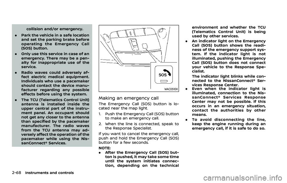
The Emergency Call (SOS) button is lo-
cated near the map light.
1. Push the Emergency Call (SOS) button
to make an emergency call.
2. When the line is connected, speak to the Response Specialist.
If you want to cancel the emergency call,
push and hold the Emergency Call (SOS)
button for a few seconds.
NOTE:
. After the Emergency Call (SOS) but-
ton is pushed, it may take some time
until the system initiates connec-
tion, depending on the technical environment and whether the TCU
(Telematics Control Unit) is being
used by other services.
. An indicator light on the Emergency
Call (SOS) button shows the readi-
ness of the emergency support sys-
tem. If the indicator light is not
illuminated, pushing the Emergency
Call (SOS) button does not connect
your vehicle to the Response Spe-
cialist.
The indicator light blinks while con-
nected to the NissanConnect® Ser-
vices Response Center.
. Even when the indicator light is
illuminated, connection to the Nis-
sanConnect® Services Response
Center may not be possible. If this
occurs in an emergency situation,
contact the authorities by other
means.
. To avoid disconnecting the line,
keep the engine running during an
emergency call, if it is safe to do so.
Page 215 of 604
the vehicle when refueling.
. Do not attempt to top off the fuel
tank after the fuel pump nozzle
shuts off automatically. Contin-
ued refueling may cause fuel
overflow, resulting in fuel spray
and possibly a fire.
. Use only an original equipment
type fuel-filler cap as a replace-
ment. It has a built-in safety valve
needed for proper operation of
the fuel system and emission
control system. An incorrect cap
can result in a serious malfunc-
tion and possible injury. It could
also cause the malfunction indi-
cator light to come on.
. Never pour fuel into the throttle
body to attempt to start your
vehicle.
. Do not fill a portable fuel contain-
er in the vehicle or trailer. Static
electricity can cause an explosion
of flammable liquid, vapor or gas
in any vehicle or trailer. To reduce
the risk of serious injury or death
when filling portable fuel contain-
ers:
— Always place the container on
the ground when filling. — Do not use electronic devices
when filling.
— Keep the pump nozzle in con- tact with the container while
you are filling it.
— Use only approved portable fuel containers for flammable
liquid.
CAUTION
. If fuel is spilled on the vehicle
body, flush it away with water to
avoid paint damage.
. Insert the cap straight into the
fuel-filler tube, then tighten until
the fuel-filler cap clicks. Failure to
tighten the fuel-filler cap properly
may cause the
malfunction
indicator light (MIL) to illuminate.
If the
light illuminates be-
cause the fuel-filler cap is loose
or missing, tighten or install the
cap and continue to drive the
vehicle. The
light should turn
off after a few driving trips. If the
light does not turn off after a
few driving trips, have the vehicle
inspected. It is recommended you visit a NISSAN dealer for this
service.
. The Loose Fuel Cap warning will
appear if the fuel-filler cap is not
properly tightened. It may take a
few driving trips for the message
to be displayed. Failure to tighten
the fuel-filler cap properly after
the Loose Fuel Cap warning ap-
pears may cause the
Mal-
function Indicator Light (MIL) to
illuminate.
Turn the cap counterclockwise to re-
move. To tighten, turn the cap clockwise
until a single click is heard.
Pre-driving checks and adjustments3-27
Page 317 of 604
dry grass, waste paper or rags.
They may ignite and cause a fire.
CAUTION
.Do not use leaded gasoline. De-
posits from leaded gasoline ser-
iously reduce the three-way
catalyst’s ability to help reduce
exhaust pollutants.
. Keep your engine tuned up. Mal-
functions in the ignition, fuel in-
jection, or electrical systems can
cause overrich fuel flow into the
three-way catalyst, causing it to
overheat. Do not keep driving if
the engine misfires, or if notice-
able loss of performance or other
unusual operating conditions are
detected. Have the vehicle in-
spected. It is recommended you
visit a NISSAN dealer for this
service.
. Avoid driving with an extremely
low fuel level. Running out of fuel
could cause the engine to misfire,
damaging the three-way catalyst.
. Do not race the engine while
warming it up. .
Do not push or tow your vehicle
to start the engine.
TIRE PRESSURE MONITORING SYS-
TEM (TPMS)
Each tire, including the spare (if provided),
should be checked monthly when cold
and inflated to the inflation pressure
recommended by the vehicle manufac-
turer on the vehicle placard or tire infla-
tion pressure label. (If your vehicle has
tires of a different size than the size
indicated on the vehicle placard or tire
inflation pressure label, you should deter-
mine the proper tire inflation pressure for
those tires.)
As an added safety feature, your vehicle
has been equipped with a Tire Pressure
Monitoring System (TPMS) that illumi-
nates a low tire pressure telltale when
one or more of your tires is significantly
under-inflated. Accordingly, when the low
tire pressure telltale illuminates, you
should stop and check your tires as soon
as possible, and inflate them to the
proper pressure. Driving on a significantly
under-inflated tire causes the tire to
overheat and can lead to tire failure.
Under-inflation also reduces fuel effi-
ciency and tire tread life, and may affect
the vehicle’s handling and stopping abil-
ity. Please note that the TPMS is not a
substitute for proper tire maintenance,
and it is the driver’s responsibility to
maintain correct tire pressure, even if
under-inflation has not reached the level
to trigger illumination of the TPMS low
tire pressure telltale.
Your vehicle has also been equipped with
a TPMS malfunction indicator to indicate
when the system is not operating prop-
erly. The TPMS malfunction indicator is
combined with the low tire pressure tell-
tale. When the system detects a malfunc-
tion, the telltale will flash for
approximately one minute and then re-
main continuously illuminated. This se-
quence will continue upon subsequent
vehicle start-ups as long as the malfunc-
tion exists. When the malfunction indica-
tor is illuminated, the system may not be
able to detect or signal low tire pressure
as intended. TPMS malfunctions may
occur for a variety of reasons, including
the installation of replacement or alter-
nate tires or wheels on the vehicle that
prevent the TPMS from functioning prop-
erly. Always check the TPMS malfunction
telltale after replacing one or more tires
or wheels on your vehicle to ensure that
the replacement or alternate tires and
wheels allow the TPMS to continue to
function properly.
Starting and driving5-5