Page 150 of 644
High Beam Assist
The High Beam Assist system will operate
when the vehicle is driven at speeds of ap-
proximately 25 mph (40 km/h) and above. If
an oncoming vehicle or leading vehicle ap-
pears in front of your vehicle when the
headlight high beam is on, the headlight
will be switched to the low beam
automatically.
WARNING
• The High Beam Assist system is a
convenience but it is not a substitute
for safe driving operation. The driver
should remain alert at all times, en-
sure safe driving practices and
switch the high beams and low beam
manually when necessary.
• The high beam or low beam may not
switch automatically under the fol-
lowing conditions. Switch the high
beam and low beam manually.
– During bad weather (rain, fog,
snow, wind, etc.).
– When a light source similar to a
headlight or tail light is in the vi-
cinity of the vehicle. –
When the headlights of the on-
coming vehicle or the leading ve-
hicle are turned off, when the color
of the light is affected due to for-
eign materials on the lights, or
when the light beam is out of
position.
– When there is a sudden, continu-
ous change in brightness.
– When driving on a road that
passes over rolling hills, or a road
that has level differences.
– When driving on a road with many
curves.
– When a sign or mirror-like surface
is reflecting intense light towards
the front of the vehicle.
– When the container, etc. being
towed by a leading vehicle is re-
flecting intense light.
– When a headlight on your vehicle
is damaged or dirty.
– When the vehicle is leaning at an
angle due to a punctured tire, be-
ing towed, etc. •
The timing of switching the low
beam and high beam may change
under the following situations.
– The brightness of the headlights
of the oncoming vehicle or leading
vehicle.
– The movement and direction of
the oncoming vehicle and the
leading vehicle.
– When only one light on the on-
coming vehicle or the leading ve-
hicle is illuminated.
– When the oncoming vehicle or the
leading vehicle is a two-wheeled
vehicle.
– Road conditions (incline, curve,
the road surface, etc.).
– The number of passengers and
the amount of luggage.
2-60Instruments and controls
Page 154 of 644
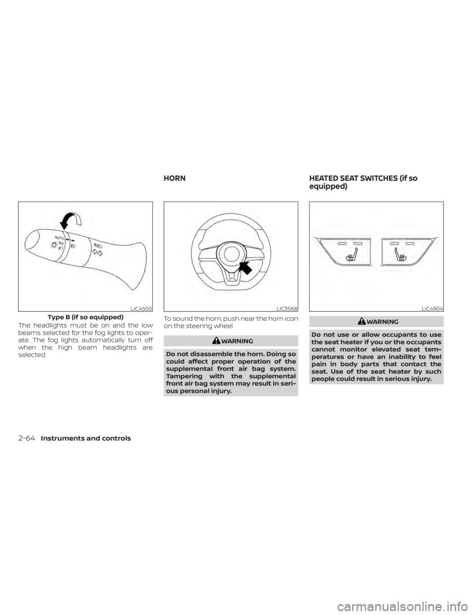
The headlights must be on and the low
beams selected for the fog lights to oper-
ate. The fog lights automatically turn off
when the high beam headlights are
selected.To sound the horn, push near the horn icon
on the steering wheel.
WARNING
Do not disassemble the horn. Doing so
could affect proper operation of the
supplemental front air bag system.
Tampering with the supplemental
front air bag system may result in seri-
ous personal injury.
WARNING
Do not use or allow occupants to use
the seat heater if you or the occupants
cannot monitor elevated seat tem-
peratures or have an inability to feel
pain in body parts that contact the
seat. Use of the seat heater by such
people could result in serious injury.
LIC4500
Type B (if so equipped)
LIC3568LIC4904
HORN HEATED SEAT SWITCHES (if so
equipped)
2-64Instruments and controls
Page 155 of 644
CAUTION
• The battery could run down if the
seat heater is operated while the en-
gine is not running.
• Do not use the seat heater for ex-
tended periods or when no one is us-
ing the seat.
• Do not put anything on the seat
which insulates heat, such as a blan-
ket, cushion, seat cover, etc. Other-
wise, the seat may become
overheated.
• Do not place anything hard or heavy
on the seat or pierce it with a pin or
similar object. This may result in
damage to the heater.
• Any liquid spilled on the heated seat
should be removed immediately with
a dry cloth.
• When cleaning the seat, never use
gasoline, benzine, thinner, or any
similar materials.
• If any malfunctions are found or the
heated seat does not operate, turn
the switch off and have the system
checked. It is recommended that you
visit a NISSAN dealer for this service. The front seats are warmed by built-in
heaters.
1. Place the ignition switch in the ON
position.
2. Push the switch until either two lights are illuminated for high setting, or one
light is illuminated for low setting.
The heater is controlled by a thermostat,
automatically turning the heater on and
off. The indicator light will remain on as
long as the switch is on.
3. When the seat is warmed or before you leave the vehicle, be sure to push the
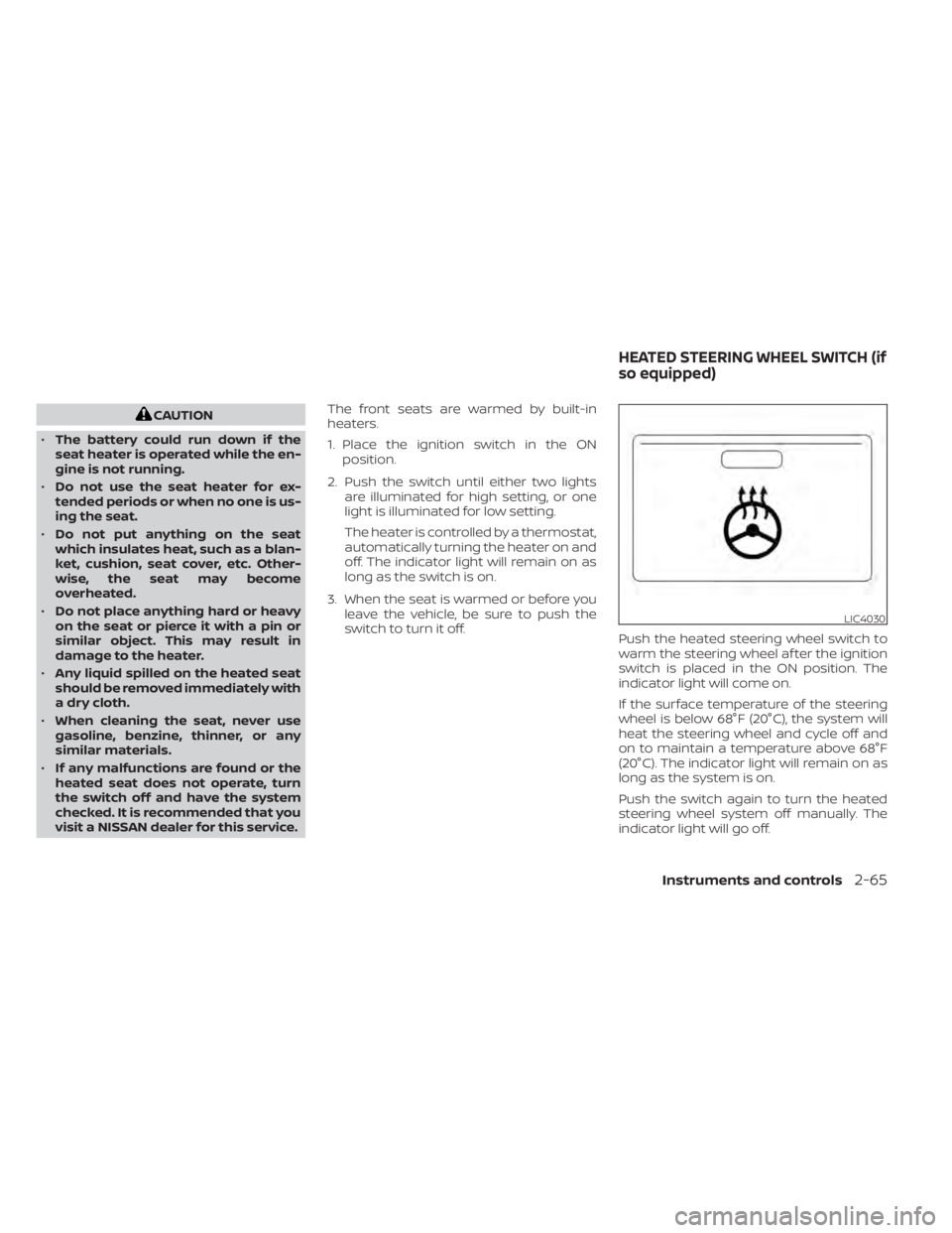
switch to turn it off. Push the heated steering wheel switch to
warm the steering wheel af ter the ignition
switch is placed in the ON position. The
indicator light will come on.
If the surface temperature of the steering
wheel is below 68°F (20°C), the system will
heat the steering wheel and cycle off and
on to maintain a temperature above 68°F
(20°C). The indicator light will remain on as
long as the system is on.
Push the switch again to turn the heated
steering wheel system off manually. The
indicator light will go off.
LIC4030
HEATED STEERING WHEEL SWITCH (if
so equipped)
Instruments and controls2-65
Page 156 of 644
NOTE:
• Once activated, your heated steeringwheel will automatically turn on and
off to maintain a temperature above
68°F (20°C).
• When the temperature of the steering wheel is above 122°F (50°C) and the
heated steering wheel switch is turned
on, the system will not heat the steer-
ing wheel. This does not indicate a
malfunction.
The Steering Assist switch is used to en-
able and disable the Steering Assist sys-
tem that is activated using the settings
menu of the vehicle information display.
The Steering Assist system controls the
steering system, when ProPILOT Assist is
engaged, to help keep your vehicle near
the center of the lane when driving. For
additional information, see ”ProPILOT As-
sist” (P. 5-94) and “Intelligent Lane Interven-
tion (I-LI)” (P. 5-40).
LIC4101
STEERING ASSIST SWITCH (for
vehicles with ProPILOT Assist) (if so
equipped)
2-66Instruments and controls
Page 160 of 644
There is a USB/iPod® charging port located
on the rear center console. This port will
charge compatible devices.
NOTE:
Only the USB connection port located
below the instrument panel will allow
operation of the USB/iPod® devices
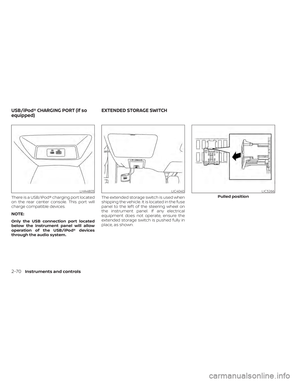
through the audio system.The extended storage switch is used when
shipping the vehicle. It is located in the fuse
panel to the lef t of the steering wheel on
the instrument panel. If any electrical
equipment does not operate, ensure the
extended storage switch is pushed fully in
place, as shown.
LHA4803LIC4040LIC3266
Pulled position
USB/iPod® CHARGING PORT (if so
equipped)
EXTENDED STORAGE SWITCH
2-70Instruments and controls
Page 177 of 644
3 Pre-driving checks and adjustments
Keys.............................................3-2NISSAN Intelligent Key® (if so equipped) .......3-2
NISSAN Vehicle Immobilizer System
keys..........................................3-4
Doors ...........................................3-4
Locking with key .............................3-5
Locking with inside lock knob ................3-6
Locking with power door lock switch .........3-6
Automatic door locks ........................3-6
Child safety rear door lock .................... 3-7
NISSAN Intelligent Key® (if so equipped) .......... 3-7
Operating range .............................3-9
Door locks/unlocks precaution ...............3-9
NISSAN Intelligent Key® operation ...........3-10
How to use the remote keyless entry
function ..................................... 3-14
Warning signals ............................. 3-16
Troubleshooting guide ......................3-16
Remote Engine Start ........................... 3-19
Remote Engine Start operating range .......3-19
Remote starting the vehicle .................3-20
Extending engine run time ..................3-20
Canceling a Remote Engine Start ...........3-20
Conditions the Remote Engine Start will
notwork .................................... 3-21Hood
........................................... 3-22
Trunk lid ........................................ 3-22
Opener operation ........................... 3-22
Interior trunk lid release .....................3-24
Interior trunk access ........................ 3-24
Fuel-filler door .................................. 3-25
Opener operation ........................... 3-25
Fuel-filler cap ................................ 3-25
Steering wheel ................................. 3-27
Tilt operation ................................ 3-27
Telescopic operation ........................ 3-27
Sun visors ...................................... 3-28
Vanity mirrors ............................... 3-29
Mirrors ......................................... 3-29
Manual anti-glare rearview mirror
(if so equipped) .............................. 3-29
Automatic anti-glare rearview mirror
(if so equipped) .............................. 3-29
Outside mirrors .............................
3-30
Memor
y seat (if so equipped) ...................3-31
Memory storage function ...................3-31
Memory storage function (switch) ...........3-32
Entry/exit function .......................... 3-33
System operation ........................... 3-33
Page 203 of 644
3. Press the OK button on the steeringwheel for about 1 second to turn off the
Loose Fuel Cap warning af ter tightening
the fuel-filler cap.WARNING
• Do not adjust the steering wheel
while driving. You could lose control
of your vehicle and cause an
accident.
• Do not adjust the steering wheel any
closer to you than is necessary for
proper steering operation and com-
fort. The driver's air bag inflates with
great force. If you are unrestrained,
leaning forward, sitting sideways or
out of position in any way, you are at
greater risk of injury or death in a
crash. You may also receive serious
or fatal injuries from the air bag if you
are up against it when it inflates. Al-
ways sit back against the seatback
and as far away as practical from the
steering wheel. Always use the seat
belts.
TILT OPERATION
Pull the lock lever down and hold on until
the end of the stroke
O1and adjust the
steering wheel up or down
O2to the de-
sired position.
Push the lock lever up
O1firmly and hold on
until end of stroke to lock the steering
wheel in place.
TELESCOPIC OPERATION
Pull the lock lever downO1and adjust the
steering wheel forward or backward
O3to
the desired position.
LPD2871
STEERING WHEEL
Pre-driving checks and adjustments3-27
Page 204 of 644
Push the lock lever upO1firmly and hold on
until end of stroke to lock the steering
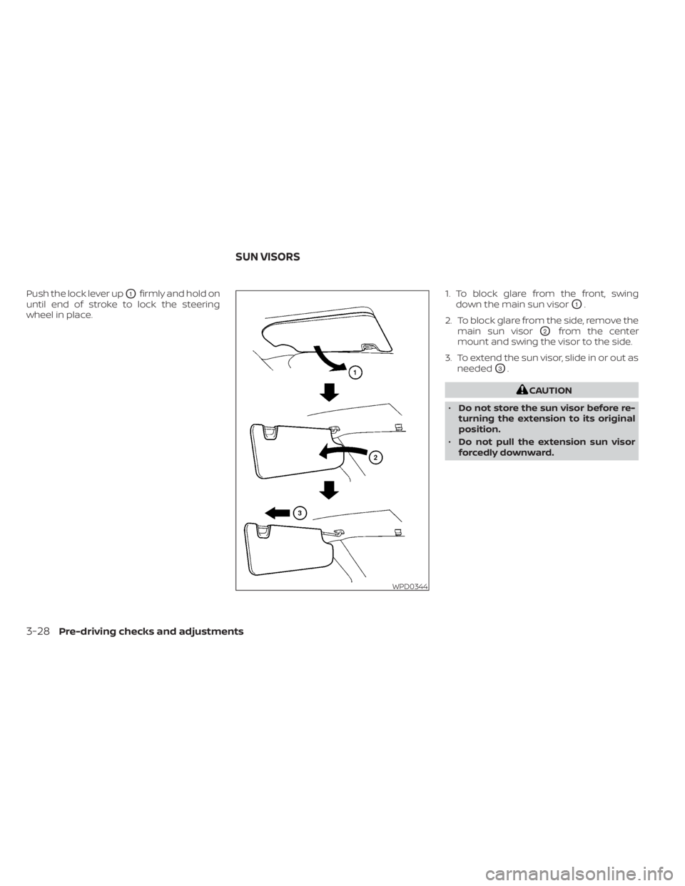
wheel in place. 1. To block glare from the front, swing
down the main sun visor
O1.
2. To block glare from the side, remove the main sun visor
O2from the center
mount and swing the visor to the side.
3. To extend the sun visor, slide in or out as needed
O3.
CAUTION
• Do not store the sun visor before re-
turning the extension to its original
position.
• Do not pull the extension sun visor
forcedly downward.
WPD0344
SUN VISORS
3-28Pre-driving checks and adjustments