2023 HYUNDAI IONIQ 5 instrument panel
[x] Cancel search: instrument panelPage 142 of 680

03
3-55
The SRSCM (Supplemental Restraint
System Control Module) continually
monitors all SRS components while the
Start/Stop button is ON to determine if a
crash impact is severe enough to require
air bag deployment or pre-tensioner seat
belt deployment.
SRS warning light
The SRS (Supplemental Restraint System)
air bag warning light on the instrument
panel displays the air bag symbol
depicted in the illustration. The system
checks the air bag electrical system for
malfunctions. The light indicates that
there is a potential problem with your
air bag system, which could include
your side and/or curtain air bags used
for rollover protection (if equipped with
rollover sensor).
WARNING
If your SRS malfunctions, the air bag
may not inflate properly during an
accident increasing the risk of serious
injury or death.
If any of the following conditions occur,
your SRS is malfunctioning: • The light does not turn on for
approximately three to six seconds
when the Start/Stop button is in the ON position.
• The light stays on after illuminating
for approximately three to six
seconds.
• The light comes on while the vehicle
is in motion.
• The light blinks when the vehicle is running.
Have an authorized HYUNDAI dealer inspect the SRS as soon as possible if
any of these conditions occur. During a moderate to severe frontal
collision, sensors will detect the
vehicle’s rapid deceleration. If the rate of
deceleration is high enough, the control
unit will inflate the front air bags, at the
time and with the force needed.
The front air bags help protect the driver
and front passenger by responding to
frontal impacts in which seat belts alone
cannot provide adequate restraint. When
needed, the side air bags help provide
protection in the event of a side impact
or rollover by supporting the side upper
body area. •
Air bags are activated (able to inflate
if necessary) only when the Start/Stop
button is in the ON or START position,
and it can be activated within about 3
minutes after the vehicle is turned off.
• Air bags inflate in the event of certain
frontal or side collisions to help
protect the occupants from serious
physical injury.
• Generally, air bags are designed to
inflate based upon the severity of a
collision, its direction, or etc. These
two factors determine whether
the sensors produce an electronic
deployment/inflation signal.
• The front air bags will completely
inflate and deflate in an instant. It is
virtually impossible for you to see the
air bags inflate during an accident. It is
much more likely that you will simply
see the deflated air bags hanging out
of their storage compartments after the collision.
Page 144 of 680
03
3-57
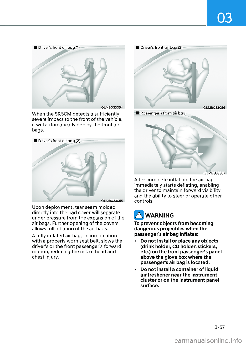
„„Driver’s front air bag (1)
OLMB033054
When the SRSCM detects a sufficiently
severe impact to the front of the vehicle,
it will automatically deploy the front air bags.
„„Driver’s front air bag (2)
OLMB033055
Upon deployment, tear seam molded
directly into the pad cover will separate
under pressure from the expansion of the
air bags. Further opening of the covers
allows full inflation of the air bags.
A fully inflated air bag, in combination
with a properly worn seat belt, slows the
driver’s or the front passenger’s forward
motion, reducing the risk of head and
chest injury.
„„Driver’s front air bag (3)
OLMB033056
„„Passenger’s front air bag
OLMB033057
After complete inflation, the air bag
immediately starts deflating, enabling
the driver to maintain forward visibility
and the ability to steer or operate other
controls.
WARNING
To prevent objects from becoming
dangerous projectiles when the
passenger’s air bag inflates: • Do not install or place any objects
(drink holder, CD holder, stickers,
etc.) on the front passenger’s panel
above the glove box where the
passenger’s air bag is located.
• Do not install a container of liquid
air freshener near the instrument
cluster or on the instrument panel
surface.
Page 146 of 680
03
3-59
Occupant Classification System
(OCS)
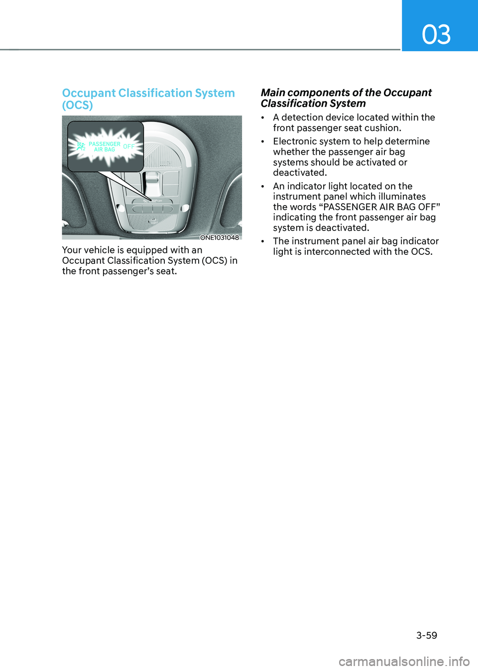
ONE1031048
Your vehicle is equipped with an
Occupant Classification System (OCS) in
the front passenger’s seat. Main components of the Occupant
Classification System •
A detection device located within the
front passenger seat cushion.
• Electronic system to help determine
whether the passenger air bag
systems should be activated or
deactivated.
• An indicator light located on the
instrument panel which illuminates
the words “PASSENGER AIR BAG OFF”
indicating the front passenger air bag
system is deactivated.
• The instrument panel air bag indicator
light is interconnected with the OCS.
Page 157 of 680
Seats & Safety System
3-70
SRS Care
The SRS is virtually maintenance-free
and there are no parts you can safely
service by yourself. If the SRS air bag
warning light does not illuminate
when the Start/Stop button is in the
ON position, or continuously remains
on, have the system be immediately
inspected by an authorized HYUNDAI
dealer.
We recommend any work on the SRS
system, such as removing, installing,
repairing, or any work on the steering
wheel, the front passenger’s panel, front
seats and roof rails be performed by an
authorized HYUNDAI dealer. Improper
handling of the SRS system may result in
serious personal injury. WARNING
To reduce the risk of serious injury or
death take the following precautions: • Do not attempt to modify or
disconnect the SRS components or
wiring, including the addition of any
kind of badges to the pad covers or
modifications to the body structure.
• Do not place objects over or near
the air bag modules on the steering
wheel, instrument panel, and the
front passenger’s panel above the
glove box.
• Clean the air bag pad covers with
a soft cloth moistened with plain
water. Solvents or cleaners could
adversely affect the air bag covers
and proper deployment of the
system.
• Have the inflated air bags be
replaced by an authorized HYUNDAI
dealer.
• If components of the air bag system
must be discarded, or if the vehicle
must be scrapped, certain safety
precautions must be observed.
Consult an authorized HYUNDAI
dealer for the necessary information.
Failure to follow these precautions
could increase the risk of personal
injury.
Page 159 of 680

4
4. Instrument Cluster
Instrument Cluster ............................................................................................ 4-4
Instrument Cluster Control .......................................................................................... 4-5
Instrument panel illumination ................................................................................... 4-5
Gauges and Meters ...................................................................................................... 4-5
Speedometer ............................................................................................................. 4-5
Power/Charge Gauge ................................................................................................. 4-6
State of Charge (SOC) Gauge for High Voltage Battery ...........................................4-6
Outside temperature gauge ...................................................................................... 4 -7
Odometer .................................................................................................................. 4-8
Distance to empty .................................................................................................... 4-8
Reduction Gear Shift Indicator ................................................................................... 4-9
Regenerative braking level indicator ....................................................................... 4-9
Warning and Indicator Lights ..................................................................................... 4-9
Ready indicator ......................................................................................................... 4-9
Service warning light ................................................................................................ 4-9
Power down indicator light ..................................................................................... 4-10
Charging indicator light ........................................................................................... 4-10
High voltage battery level warning light ................................................................4-10
Seat belt warning light ............................................................................................ 4-10
Air bag warning light ................................................................................................ 4-11
Regenerative brake warning light ............................................................................ 4-11
Parking brake & brake fluid warning light ...............................................................4-11
Anti-lock Brake System (ABS) warning light ..........................................................4-12
Electronic Brake Force Distribution (EBD) system warning light .........................4-12
Electric Power Steering (EPS) warning light ..........................................................4-13
Master warning light ................................................................................................ 4-13
Electronic Parking Brake (EPB) warning light ........................................................4-14
Low tire pressure warning light .............................................................................. 4-14
Forward safety warning light .................................................................................. 4-15
Lane safety indicator light ...................................................................................... 4-15
All Wheel Drive (AWD) warning light ...................................................................... 4-15
LED headlight warning light .................................................................................... 4-16
Icy road warning light .............................................................................................. 4-16
Electronic Stability Control (ESC) indicator light ....................................................4-17
Electronic Stability Control (ESC) OFF indicator light ............................................4-17
Immobilizer indicator light ....................................................................................... 4-17
Turn signal indicator light ........................................................................................ 4-18
High beam indicator light ....................................................................................... 4-18
Light ON indicator light ........................................................................................... 4-18
High Beam Assist indicator light (if equipped) ......................................................4-19
AUTO HOLD indicator light ..................................................................................... 4-19
Page 163 of 680
04
4-5
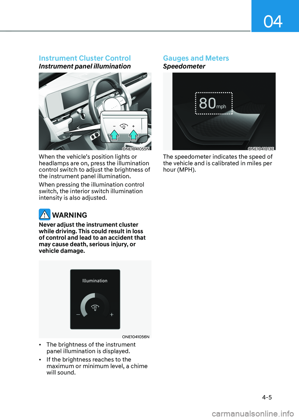
Instrument Cluster Control
Instrument panel illumination
ONE1041055N
When the vehicle’s position lights or
headlamps are on, press the illumination
control switch to adjust the brightness of
the instrument panel illumination.
When pressing the illumination control
switch, the interior switch illumination
intensity is also adjusted.
WARNING
Never adjust the instrument cluster
while driving. This could result in loss
of control and lead to an accident that
may cause death, serious injury, or
vehicle damage.
ONE1041056N
• The brightness of the instrument
panel illumination is displayed.
• If the brightness reaches to the
maximum or minimum level, a chime will sound.
Gauges and Meters
Speedometer
ONE1041013E
The speedometer indicates the speed of
the vehicle and is calibrated in miles per hour (MPH).
Page 278 of 680
Convenience Features
5-86
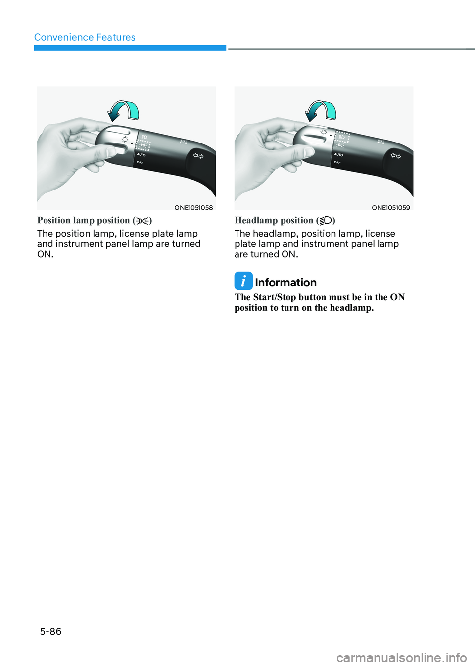
ONE1051058
Position lamp position ()
The position lamp, license plate lamp
and instrument panel lamp are turned ON.
ONE1051059
Headlamp position ()
The headlamp, position lamp, license
plate lamp and instrument panel lamp
are turned ON.
Information
The Start/Stop button must be in the ON position to turn on the headlamp.
Page 286 of 680
Convenience Features
5-94
High Beam Assist Operation
Display and control • After selecting ‘High Beam Assist’
in the Settings menu, High Beam
Assist will operate by following the
procedure below.
- Place the headlamp switch in the AUTO position and push
the headlamp lever towards the
instrument cluster. The High Beam
Assist (
) indicator light will
illuminate on the cluster and High
Beam Assist will be enabled.
- When High Beam Assist is enabled, high beam will turn on when vehicle
speed is above 40 km/h (25 mph).
When vehicle speed is below 25
km/h (15 mph), high beam will turn
off.
- The High Beam (
) indicator light
will illuminate on the cluster when high beam is on.
• When High Beam Assist is operating, if
the headlamp lever or switch is used,
High Beam Assist operates as follow:
- If the headlamp lever is pulled towards you when the high beam
is off, the high beam will turn on
without High Beam Assist canceled.
When you let go of the headlamp
lever, the lever will move to the middle and the high beam will turn
off.
- If the headlamp lever is pulled towards you when the high beam is
on by High Beam Assist, low beam will turn on and the function will
turn off.
- If the headlamp switch is placed from AUTO to another position
(headlamp/position/off), High
Beam Assist will turn off and the
corresponding lamp will turn on. •
When High Beam Assist is operating,
high beam switches to low beam if
any of the following conditions occur:
- When the headlamp of an oncoming vehicle is detected.
- When the tail lamp of a vehicle in front is detected.
- When the headlamp or tail lamp of a motorcycle or a bicycle is detected.
- When the surrounding ambient light is bright enough that high beams
are not required.
- When streetlights or other lights are detected.
Information
The images or colors may be displayed
differently depending on the specifications
of the instrument panel or theme.