2023 GMC SIERRA ignition
[x] Cancel search: ignitionPage 321 of 430

GMC Sierra/Sierra Denali 2500 HD/3500 HD Owner Manual (GMNA-
Localizing-U.S./Canada-16504257) - 2023 - CRC - 5/18/22
320 Vehicle Care
Extended Storage: Remove the black,
negative (−) cable from the battery or use a
battery trickle charger.
Negative Battery Cable Disconnection
{Warning
Before disconnecting the negative battery
cable, turn off all features, turn the
ignition off, and remove the key,
if equipped, from the vehicle. If this is
not done, you or others could be injured,
and the vehicle could be damaged.
Caution
If the battery is disconnected with the
ignition on or the vehicle in Retained
Accessory Power (RAP), the OnStar
back-up battery will be permanently
discharged and will need to be replaced.
1. Make sure the lamps, features, and accessories are turned off.
2. Turn the ignition off and remove the key, if equipped.
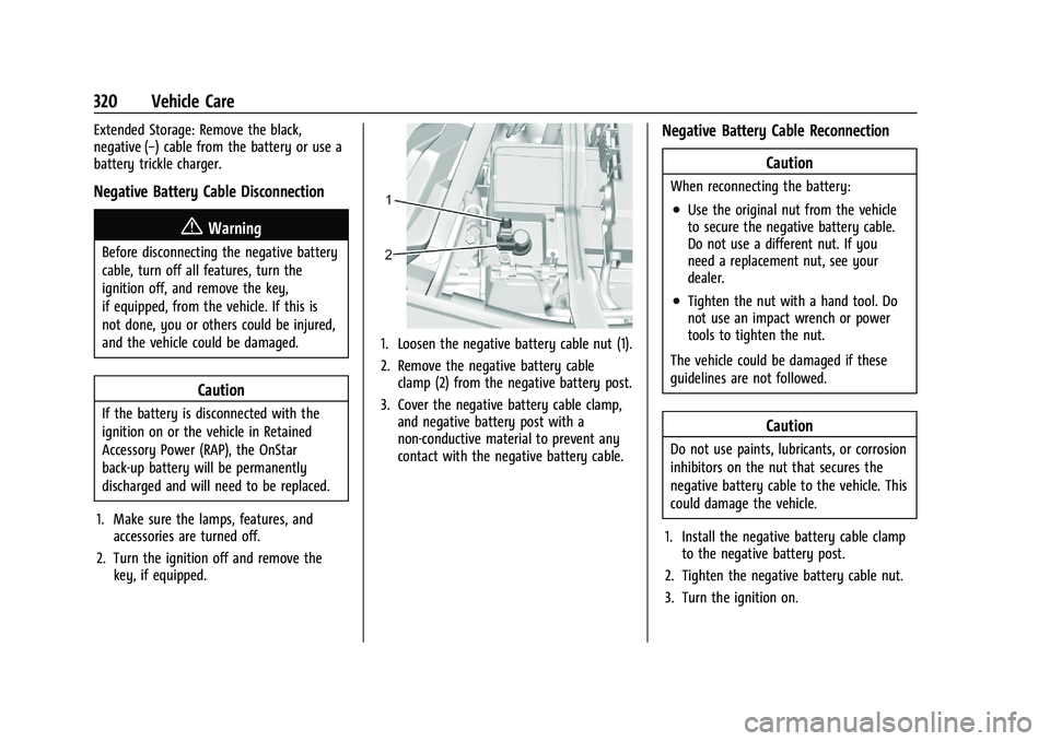
1. Loosen the negative battery cable nut (1).
2. Remove the negative battery cableclamp (2) from the negative battery post.
3. Cover the negative battery cable clamp, and negative battery post with a
non-conductive material to prevent any
contact with the negative battery cable.
Negative Battery Cable Reconnection
Caution
When reconnecting the battery:
.Use the original nut from the vehicle
to secure the negative battery cable.
Do not use a different nut. If you
need a replacement nut, see your
dealer.
.Tighten the nut with a hand tool. Do
not use an impact wrench or power
tools to tighten the nut.
The vehicle could be damaged if these
guidelines are not followed.
Caution
Do not use paints, lubricants, or corrosion
inhibitors on the nut that secures the
negative battery cable to the vehicle. This
could damage the vehicle.
1. Install the negative battery cable clamp to the negative battery post.
2. Tighten the negative battery cable nut.
3. Turn the ignition on.
Page 323 of 430

GMC Sierra/Sierra Denali 2500 HD/3500 HD Owner Manual (GMNA-
Localizing-U.S./Canada-16504257) - 2023 - CRC - 5/18/22
322 Vehicle Care
General Motors LLC, and is not limited to
any particular part, component or system of
the vehicle manufactured by General Motors
LLC. Defects in design, assembly or in any
part, component or system of the vehicle as
manufactured by General Motors LLC, which,
at the time it left General Motors LLC’s
control, caused noise emissions to exceed
Federal standards, are covered by this
warranty for the life of the vehicle.
TAMPERING WITH NOISE CONTROL
SYSTEM PROHIBITED
Federal law prohibits the following acts or
the causing thereof:1. The removal or rendering inoperative by any person, other than for purposes of
maintenance, repair, or replacement, of
any device or element of design
incorporated into any new vehicle for
the purpose of noise control prior to its
sale or delivery to the ultimate purchaser
or while it is in use; or
2. the use of the vehicle after such device or element of design has been removed
or rendered inoperative by any person. Among those acts presumed to constitute
tampering are the acts listed below.
Insulation:
Removal of the noise shields or any
undercab insulation.
Engine:
Removal or rendering engine speed
governor, if so equipped, inoperative so as
to allow engine speed to exceed
manufacturer specifications.
Modification of the engine control system or
calibration.
Fan and Drive:
.Removal of fan clutch or rendering clutch
inoperative.
.Removal of the fan shroud.
Air Intake:
.Removal of air cleaner silencer.
.Reversing air cleaner cover.
Exhaust:
.Removal of muffler, catalytic converter,
and/or resonator.
.Removal of exhaust pipes and exhaust
pipe clamps.
Automatic Transmission Shift Lock
Control Function Check
(Mechanical Shifter)
{Warning
When you are doing this inspection, the
vehicle could move suddenly. If the
vehicle moves, you or others could be
injured.
1. Before starting this check, be sure there is enough room around the vehicle.
It should be parked on a level surface.
2. Apply the parking brake. Be ready to apply the regular brake immediately if
the vehicle begins to move.
3. With the engine off, turn the ignition on, but do not start the engine. Without
applying the regular brake, try to move
the shift lever out of P (Park) with
normal effort. If the shift lever moves
out of P (Park), contact your dealer for
service.
Page 332 of 430

GMC Sierra/Sierra Denali 2500 HD/3500 HD Owner Manual (GMNA-
Localizing-U.S./Canada-16504257) - 2023 - CRC - 5/18/22
Vehicle Care 331
FusesUsage
6 –
7 –
8 Fog lamp
9 –
10 –
11 Police upfitter
12 –
13 Washer front
14 Washer rear 15 –
16 –
17 IECL 1
19 DC/AC inverter
20 IECR 2 (LD) / EBCM2 (HD)
21 –
22 IECL 2
24 EBCM 1 25 –
26 – Fuses
Usage
27 Horn
28 –
29 –
30 –
31 –
32 Rear window defogger
33 Heated mirror
34 Parking lamp left 37 –
38 –
39 –
40 Misc ignition 41 Trailer parking lamp
42 Park lamp right
44 –
45 –
46 Engine control module ignition
47 Transmission control module ignition Fuses
Usage
48 –
49 Transmission control module
50 A/C clutch 51 Transfer case control module
52 Front wiper
53 Center high-mounted stop lamp
54 Trailer reverse lamp 55 Trailer back-up lamp
56 SADS 57 TTPM/SBZA
58 Starter motor (LD & HD DSL)
60 Active fuel management 1
61 VES
62 Integrated chassis control module/CVS
63 Trailer battery
Page 337 of 430

GMC Sierra/Sierra Denali 2500 HD/3500 HD Owner Manual (GMNA-
Localizing-U.S./Canada-16504257) - 2023 - CRC - 5/18/22
336 Vehicle Care
FusesUsage
F1 Right Doors
F2 Left Doors
F3 Universal Garage Door Opener
F4 –
F5 –
F6 Front Blower
F8 Lumbar Switch
F10 Body Control Module 6/ Body Control Module 7
F11 Seat/Column Lock Module
F12 Body Control Module 3/ Body Control Module 5
F14 Mirrors/Windows Module F17 Steering Wheel Controls
F18 Video Processing Module/ Obstacle Detection
F19 DLIS –Discrete Logic
Ignition Switch
F20 Ventilated Seats F21 NOT R/C Fuses
Usage
F22 Heated Steering Wheel
F23 MISC R/C
F24 Power Take Off/Reflective Light Auxiliary Display/
Instrument Panel Cluster/
Central Gateway Module/
Inside Rear View Mirror/
Overhead Console Module
Ignition
F25 Heating, Ventilation, and Air Conditioning Ignition/
Heating, Ventilation, and
Air Conditioning Auxiliary
F26 USB Ports/Special Equipment Option Retained
Accessory Power
F27 Accessory Power Outlet/ Retained Accessory Power
F28 Accessory Power Outlet/ Battery
F30 Sensing and Diagnostic Module/Parking Brake
F31 Body Control Module 4 Fuses
Usage
F32 Special Equipment Option/ Data Link Connection
F33 Body Control Module 8
F34 Cargo Lamp
F40 CGM –Central Gateway
Module
F41 Infotainment 1
F42 TCP –Telematics
Connectivity Platform
F43 –
F44 –
F45 Body Control Module 2
F46 Heating, Ventilation, and Air Conditioning/Battery 1
F47 Instrument Panel Cluster/ Battery
F48 Transmission Control Module
F49 Body Control Module 1 F50 –
F51 Battery 1
F52 Battery 2
Page 345 of 430

GMC Sierra/Sierra Denali 2500 HD/3500 HD Owner Manual (GMNA-
Localizing-U.S./Canada-16504257) - 2023 - CRC - 5/18/22
344 Vehicle Care
This sequence will continue upon
subsequent vehicle start-ups as long as the
malfunction exists.
When the malfunction indicator is
illuminated, the system may not be able to
detect or signal low tire pressure as
intended. TPMS malfunctions may occur for
a variety of reasons, including the
installation of replacement or alternate tires
or wheels on the vehicle that prevent the
TPMS from functioning properly. Always
check the TPMS malfunction telltale after
replacing one or more tires or wheels on
your vehicle to ensure that the replacement
or alternate tires and wheels allow the
TPMS to continue to function properly.
SeeTire Pressure Monitor Operation 0344.
See Radio Frequency Statement 0404.
Tire Pressure Monitor Operation
This vehicle may have a Tire Pressure
Monitor System (TPMS). The TPMS is
designed to warn the driver when a low tire
pressure condition exists. TPMS sensors are
mounted onto each tire and wheel
assembly, excluding the spare tire and
wheel assembly. The TPMS sensors monitor the air pressure in the tires and transmit the
tire pressure readings to a receiver located
in the vehicle.
When a low tire pressure condition is
detected, the TPMS illuminates the low tire
pressure warning light located on the
instrument cluster. If the warning light
comes on, stop as soon as possible and
inflate the tires to the recommended
pressure shown on the Tire and Loading
Information label. See
Vehicle Load Limits
0 215.
A message to check the pressure in a
specific tire displays in the Driver
Information Center (DIC). The low tire
pressure warning light and the DIC warning
message come on at each ignition cycle
until the tires are inflated to the correct
inflation pressure. If the vehicle has DIC
buttons, tire pressure levels can be viewed. For additional information and details about
the DIC operation and displays, see
Driver
Information Center (DIC) (Base Level) 0128
or
Driver Information Center (DIC) (Midlevel and
Uplevel) 0130.
The low tire pressure warning light may
come on in cool weather when the vehicle is
first started, and then turn off as the vehicle
is driven. This could be an early indicator
that the air pressure is getting low and
needs to be inflated to the proper pressure.
A Tire and Loading Information label shows
the size of the original equipment tires and
the correct inflation pressure for the tires
when they are cold. See Vehicle Load Limits
0 215, for an example of the Tire and
Loading Information label and its location.
Also see Tire Pressure 0342.
The TPMS can warn about a low tire
pressure condition but it does not replace
normal tire maintenance. See Tire Inspection
0 348, Tire Rotation 0349, and Tires0337.
Caution
Tire sealant materials are not all the
same. A non-approved tire sealant could
damage the TPMS sensors. TPMS sensor
(Continued)
Page 346 of 430

GMC Sierra/Sierra Denali 2500 HD/3500 HD Owner Manual (GMNA-
Localizing-U.S./Canada-16504257) - 2023 - CRC - 5/18/22
Vehicle Care 345
Caution (Continued)
damage caused by using an incorrect tire
sealant is not covered by the vehicle
warranty. Always use only the GM
approved tire sealant available through
your dealer or included in the vehicle.
TPMS Malfunction Light and Message
The TPMS will not function properly if one
or more of the TPMS sensors are missing or
inoperable. When the system detects a
malfunction, the low tire pressure warning
light flashes for about one minute and then
stays on for the remainder of the ignition
cycle. A DIC warning message also displays.
The malfunction light and DIC warning
message come on at each ignition cycle
until the problem is corrected. Some of the
conditions that can cause these to come
on are:
.One of the road tires has been replaced
with the spare tire. The spare tire does
not have a TPMS sensor. The malfunction
light and the DIC message should go off
after the road tire is replaced and the
sensor matching process is performed
successfully. See "TPMS Sensor Matching
Process" later in this section.
.The TPMS sensor matching process was
not done or not completed successfully
after rotating the tires. The malfunction
light and the DIC message should go off
after successfully completing the sensor
matching process. See "TPMS Sensor
Matching Process" later in this section.
.One or more TPMS sensors are missing or
damaged. The malfunction light and the
DIC message should go off when the
TPMS sensors are installed and the sensor
matching process is performed
successfully. See your dealer for service.
.Replacement tires or wheels do not match
the original equipment tires or wheels.
Tires and wheels other than those
recommended could prevent the TPMS
from functioning properly. SeeBuying
New Tires 0352.
.Operating electronic devices or being near
facilities using radio wave frequencies
similar to the TPMS could cause the TPMS
sensors to malfunction.
If the TPMS is not functioning properly, it
cannot detect or signal a low tire pressure
condition. See your dealer for service if the
TPMS malfunction light and DIC message
come on and stay on.
Tire Fill Alert (If Equipped)
This feature provides visual and audible
alerts outside the vehicle to help when
inflating an underinflated tire to the
recommended cold tire pressure.
When the low tire pressure warning light
comes on: 1. Park the vehicle in a safe, level place.
2. Set the parking brake firmly.
3. Place the vehicle in P (Park).
4. Add air to the tire that is underinflated. The turn signal lamp will flash.
When the recommended pressure is
reached, the horn sounds once and the
turn signal lamp will stop flashing and
briefly turn solid.
Repeat these steps for all underinflated tires
that have illuminated the low tire pressure
warning light.
{Warning
Overinflating a tire could cause the tire
to rupture and you or others could be
injured. Do not exceed the maximum (Continued)
Page 347 of 430

GMC Sierra/Sierra Denali 2500 HD/3500 HD Owner Manual (GMNA-
Localizing-U.S./Canada-16504257) - 2023 - CRC - 5/18/22
346 Vehicle Care
Warning (Continued)
pressure listed on the tire sidewall. See
Tire Sidewall Labeling0338 and
Vehicle Load Limits 0215.
If the tire is overinflated by more than
35 kPa (5 psi), the horn will sound multiple
times and the turn signal lamp will continue
to flash for several seconds after filling
stops. To release and correct the pressure,
while the turn signal lamp is still flashing,
briefly press the center of the valve stem.
When the recommended pressure is reached,
the horn sounds once.
If the turn signal lamp does not flash within
15 seconds after starting to inflate the tire,
the tire fill alert has not been activated or is
not working.
If the hazard warning flashers are on, the
tire fill alert visual feedback will not work
properly.
The TPMS will not activate the tire fill alert
properly under the following conditions:
.There is interference from an external
device or transmitter.
.The air pressure from the inflation device
is not sufficient to inflate the tire.
.There is a malfunction in the TPMS.
.There is a malfunction in the horn or turn
signal lamps.
.The identification code of the TPMS
sensor is not registered to the system.
.The battery of the TPMS sensor is low.
If the tire fill alert does not operate due to
TPMS interference, move the vehicle about
1 m (3 ft) back or forward and try again.
If the tire fill alert feature is not working,
use a tire pressure gauge.
TPMS Sensor Matching Process
Each TPMS sensor has a unique
identification code. The identification code
needs to be matched to a new tire/wheel
position after rotating the vehicle’s tires or
replacing one or more of the TPMS sensors.
Also, the TPMS sensor matching process
should be performed after replacing a spare
tire with a road tire containing the TPMS
sensor. The malfunction light and the DIC
message should go off at the next ignition
cycle. The sensors are matched to the tire/
wheel positions, using a TPMS relearn tool,
in the following order: driver side front tire,
passenger side front tire, passenger side rear
tire, and driver side rear. See your dealer for
service or to purchase a relearn tool. A TPMS relearn tool can also be purchased.
See Tire Pressure Monitor Sensor Activation
Tool at www.gmtoolsandequipment.com or
call 1-800-GM TOOLS (1-800-468-6657).
There are two minutes to match the first
tire/wheel position, and five minutes overall
to match all four tire/wheel positions. If it
takes longer, the matching process stops
and must be restarted.
The TPMS sensor matching process is:
1. Set the parking brake.
2. Turn the ignition on without starting the vehicle.
3. Uplevel DIC Only: Make sure the Tire Pressure info page option is turned on.
The info pages on the DIC can be turned
on and off through the Options menu.
See Driver Information Center (DIC) (Base
Level) 0128 or
Driver Information Center (DIC) (Midlevel
and Uplevel) 0130.
4. If the vehicle has an uplevel DIC, use the DIC controls on the right side of the
steering wheel to scroll to the Tire
Pressure screen under the DIC info page.
If the vehicle has a base level DIC, use
the trip odometer reset stem to scroll to
the Tire Pressure screen.
Page 359 of 430

GMC Sierra/Sierra Denali 2500 HD/3500 HD Owner Manual (GMNA-
Localizing-U.S./Canada-16504257) - 2023 - CRC - 5/18/22
358 Vehicle Care
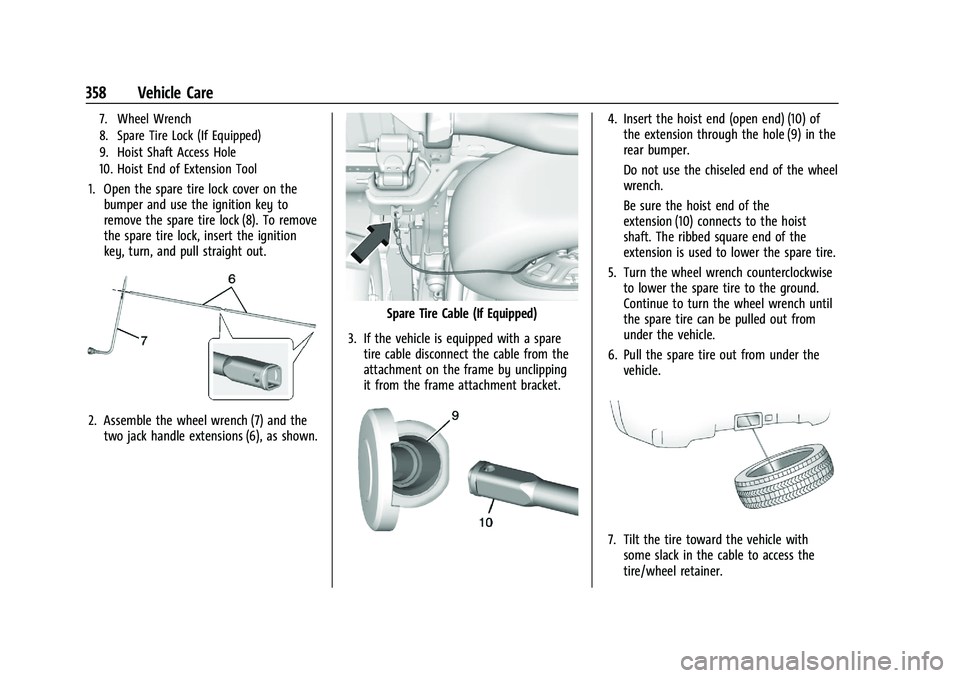
7. Wheel Wrench
8. Spare Tire Lock (If Equipped)
9. Hoist Shaft Access Hole
10. Hoist End of Extension Tool
1. Open the spare tire lock cover on thebumper and use the ignition key to
remove the spare tire lock (8). To remove
the spare tire lock, insert the ignition
key, turn, and pull straight out.
2. Assemble the wheel wrench (7) and thetwo jack handle extensions (6), as shown.
Spare Tire Cable (If Equipped)
3. If the vehicle is equipped with a spare tire cable disconnect the cable from the
attachment on the frame by unclipping
it from the frame attachment bracket.
4. Insert the hoist end (open end) (10) ofthe extension through the hole (9) in the
rear bumper.
Do not use the chiseled end of the wheel
wrench.
Be sure the hoist end of the
extension (10) connects to the hoist
shaft. The ribbed square end of the
extension is used to lower the spare tire.
5. Turn the wheel wrench counterclockwise to lower the spare tire to the ground.
Continue to turn the wheel wrench until
the spare tire can be pulled out from
under the vehicle.
6. Pull the spare tire out from under the vehicle.
7. Tilt the tire toward the vehicle withsome slack in the cable to access the
tire/wheel retainer.