2023 DODGE HORNET height
[x] Cancel search: heightPage 5 of 288

3
EXTERIOR LIGHTS ...............................................................40Multifunction Lever .................................................... 40
Headlight Switch ......................................................... 40
Daytime Running Lights (DRLs) —
If Equipped .................................................................. 40
High/Low Beam Switch ............................................. 40
Automatic High Beam Headlamp Control —
If Equipped ................................................................. 41
Flash-To-Pass .............................................................. 41
Automatic Headlights — If Equipped ......................... 41
Headlights On Automatically With Wipers —
If Equipped .................................................................. 41
Headlight Delay ........................................................... 41
Lights-On Reminder .................................................... 41
Cornering Lights — If Equipped .................................. 41
Turn Signals ................................................................ 42
Lane Change Assist ................................................... 42
Battery Saver Feature................................................. 42
INTERIOR LIGHTS................................................................42 Interior Courtesy Lights............................................... 42
WINDSHIELD WIPERS AND WASHERS ........................... 44 Windshield Wiper Operation....................................... 44
Rain Sensing Wipers — If Equipped .......................... 45
Rear Window Wiper/Washer ..................................... 46
CLIMATE CONTROLS ..........................................................46 Automatic Climate Control Descriptions And
Functions ..................................................................... 46
Automatic Temperature
Control (ATC) ............................................................... 49
Climate Voice Commands .......................................... 49
Operating Tips ............................................................ 49 INTERIOR STORAGE AND EQUIPMENT ............................ 50
Storage ......................................................................... 50
USB Control .................................................................. 51
Power Outlets — If Equipped ....................................... 52
Wireless Charging Pad —
If Equipped ................................................................... 53
WINDOWS .......................................................................... 55 Power Window Controls............................................... 55
Automatic Window Features ......................................55
Power Window System Initialization........................... 55
Window Lockout Switch ..............................................56
Wind Buffeting ............................................................ 56
POWER SUNROOF — IF EQUIPPED ................................. 56 Opening And Closing The Sunroof ..............................57
Opening And Closing The Power Sunshade ............... 57
Pinch Protect Feature.................................................. 57
Re-Initialization Procedure .......................................... 58
Sunroof Maintenance.................................................. 58
HOOD ................................................................................... 58 Opening The Hood .......................................................58
Closing The Hood ......................................................... 59
LIFTGATE .............................................................................. 59 Unlock/Open The Liftgate ........................................... 59
Lock/Close The Liftgate ..............................................60
Power Liftgate — If Equipped ......................................60
Adjustable Power Liftgate Height ............................... 61
Hands-Free Liftgate — If Equipped ............................ 62
Cargo Area Features.................................................... 63GETTING TO KNOW YOUR
INSTRUMENT PANEL
PREMIUM INSTRUMENT CLUSTER................................... 65 Instrument Cluster Descriptions
b
.......................... 66
INSTRUMENT CLUSTER DISPLAY ..................................... 66 Instrument Cluster Display Location And
Controls........................................................................ 66
Oil Change Reset
b
.................................................. 68
Oil Change Indicator System ...................................... 68
Gear Shift Indicator (GSI) —
If Equipped................................................................... 68
Instrument Cluster Display Menu Items ................... 68
Battery Saver On/Battery Saver Mode Message —
Electrical Load Reduction Actions — If Equipped ...... 70
WARNING LIGHTS AND MESSAGES ................................ 71 Red Warning Lights ..................................................... 71
Yellow Warning Lights ................................................. 73
Yellow Indicator Lights ................................................ 77
Green Indicator Lights................................................. 77
White Indicator Lights ................................................. 78
Blue Indicator Lights ................................................... 78
ONBOARD DIAGNOSTIC SYSTEM — OBD II .................... 78 Onboard Diagnostic System (OBD II)
Cybersecurity ............................................................... 79
EMISSIONS INSPECTION AND MAINTENANCE
PROGRAMS ......................................................................... 79
23_GG_OM_EN_USC_t.book Page 3
Page 30 of 288

28GETTING TO KNOW YOUR VEHICLE
MANUAL ADJUSTMENT (FRONT SEATS) —
I
F EQUIPPED
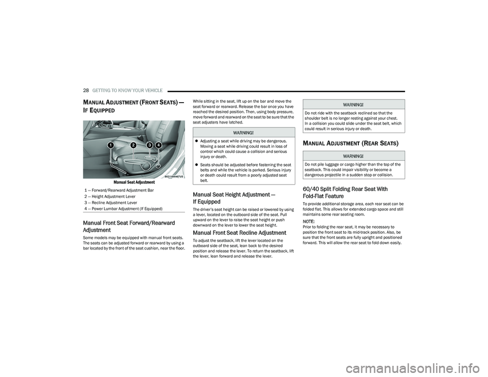
Manual Seat Adjustment
Manual Front Seat Forward/Rearward
Adjustment
Some models may be equipped with manual front seats.
The seats can be adjusted forward or rearward by using a
bar located by the front of the seat cushion, near the floor. While sitting in the seat, lift up on the bar and move the
seat forward or rearward. Release the bar once you have
reached the desired position. Then, using body pressure,
move forward and rearward on the seat to be sure that the
seat adjusters have latched.
Manual Seat Height Adjustment —
If Equipped
The driver’s seat height can be raised or lowered by using
a lever, located on the outboard side of the seat. Pull
upward on the lever to raise the seat height or push
downward on the lever to lower the seat height.
Manual Front Seat Recline Adjustment
To adjust the seatback, lift the lever located on the
outboard side of the seat, lean back to the desired
position and release the lever. To return the seatback, lift
the lever, lean forward and release the lever.
MANUAL ADJUSTMENT (REAR SEATS)
60/40 Split Folding Rear Seat With
Fold-Flat Feature
To provide additional storage area, each rear seat can be
folded flat. This allows for extended cargo space and still
maintains some rear seating room.
NOTE:Prior to folding the rear seat, it may be necessary to
position the front seat to its mid-track position. Also, be
sure that the front seats are fully upright and positioned
forward. This will allow the rear seat to fold down easily.
1 — Forward/Rearward Adjustment Bar
2 — Height Adjustment Lever
3 — Recline Adjustment Lever
4 — Power Lumbar Adjustment (If Equipped)
WARNING!
Adjusting a seat while driving may be dangerous.
Moving a seat while driving could result in loss of
control which could cause a collision and serious
injury or death.
Seats should be adjusted before fastening the seat
belts and while the vehicle is parked. Serious injury
or death could result from a poorly adjusted seat
belt.
WARNING!
Do not ride with the seatback reclined so that the
shoulder belt is no longer resting against your chest.
In a collision you could slide under the seat belt, which
could result in serious injury or death.
WARNING!
Do not pile luggage or cargo higher than the top of the
seatback. This could impair visibility or become a
dangerous projectile in a sudden stop or collision.
23_GG_OM_EN_USC_t.book Page 28
Page 31 of 288

GETTING TO KNOW YOUR VEHICLE29
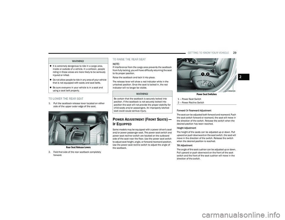
TO LOWER THE REAR SEAT
1. Pull the seatback release lever located on either
side of the upper outer edge of the seat.
Rear Seat Release Levers
2. Fold that side of the rear seatback completely forward.
TO RAISE THE REAR SEAT
NOTE:If interference from the cargo area prevents the seatback
from fully locking, you will have difficulty returning the seat
to its proper position.
Raise the seatback and lock it into place.
The release lever will show a red indicator while in the
unlocked position. Once the seat is locked in, the red
indicator will no longer be visible.
POWER ADJUSTMENT (FRONT SEATS) —
I
F EQUIPPED
Some models may be equipped with a power driver's seat
and/or power passenger seat. The power seat switch and
power seat recliner switch are located on the outboard
side of the seat near the floor. Use the power seat switch
to adjust seat height, angle, or forward/rearward position.
Use the power seat recline switch to adjust the angle of
the seatback.
Power Seat Switches
Forward Or Rearward Adjustment
The seat can be adjusted both forward and rearward. Push
the seat switch forward or rearward, the seat will move in
the direction of the switch. Release the switch when the
desired position has been reached.
Height Adjustment
The height of the seats can be adjusted up or down. Pull
upward or push downward on the seat switch, the seat will
move in the direction of the switch. Release the switch
when the desired position is reached.
Tilt Adjustment
The angle of the seat cushion can be adjusted up or down.
Pull upward or push downward on the front of the seat
switch and the front of the seat cushion will move in the
direction of the switch.
WARNING!
It is extremely dangerous to ride in a cargo area,
inside or outside of a vehicle. In a collision, people
riding in these areas are more likely to be seriously
injured or killed.
Do not allow people to ride in any area of your vehicle
that is not equipped with seats and seat belts.
Be sure everyone in your vehicle is in a seat and
using a seat belt properly.
WARNING!
Be certain that the seatback is securely locked into
position. If the seatback is not securely locked into
position the seat will not provide the proper stability for
child seats and/or passengers. An improperly latched
seat could cause serious injury.1 — Power Seat Switch
2 — Power Recline Switch
2
23_GG_OM_EN_USC_t.book Page 29
Page 34 of 288

32GETTING TO KNOW YOUR VEHICLE
(Continued)
Front Head Restraint Adjustment
Your vehicle is equipped with front two-way driver and
passenger head restraints.
To raise the head restraint, pull upward on the head
restraint. To lower the head restraint, push the adjustment
button, located at the base of the head restraint, and push
downward on the head restraint.
Head Restraint Adjustment
Rear Head Restraint Adjustment
The rear outboard head restraints can be adjusted up or
down.
To raise the outboard head restraint, pull upward on the
head restraint. To lower the head restraint, push the
adjustment button, located at the base of the head
restraint, and push downward on the head restraint.
Outboard Head Restraint Adjustment Button
Head Restraint Removal
To remove the front or rear outboard head restraints,
proceed as follows:
1. Raise the head restraint to its maximum height.
2. Push the adjustment button and the release button
at the side of the two supports at the same time.
3. Pull upward on the head restraint to fully remove it.
To reinstall the head restraints, proceed as follows:
1. Hold down both the adjustment button and release button while placing the head restraint posts into
the holes.
2. Then, reposition the head restraint to the appropriate height for the passengers.
3. Replace the seatback to the appropriate position for passengers.
NOTE:The rear center head restraint is fixed, and is not
adjustable or removable.
1 — Release Button
2 — Adjustment Button
WARNING!
All occupants, including the driver, should not
operate a vehicle or sit in a vehicle’s seat until the
head restraints are placed in their proper positions in
order to minimize the risk of neck injury in the event
of a crash.
Head restraints should never be adjusted while the
vehicle is in motion. Driving a vehicle with the head
restraints improperly adjusted or removed could
cause serious injury or death in the event of
a collision.
WARNING!
ALL the head restraints MUST be reinstalled in the
vehicle to properly protect the occupants.
WARNING!
WARNING!
A loose head restraint thrown forward in a collision or
hard stop could cause serious injury or death to occu -
pants of the vehicle. Always securely stow removed
head restraints in a location outside the occupant
compartment.
ALL the head restraints MUST be reinstalled in the
vehicle to properly protect the occupants. Follow the
preceding reinstallation instructions prior to oper -
ating the vehicle or occupying a seat.
23_GG_OM_EN_USC_t.book Page 32
Page 63 of 288

GETTING TO KNOW YOUR VEHICLE61
NOTE:
Before closing the liftgate, make sure to be in posses -
sion of the key fob because the liftgate may be locked.
Use the interior door lock/unlock button on the door
panel or the key fob to lock and unlock the liftgate. The
manual door locks on the doors and the exterior door
lock cylinder will not lock and unlock the liftgate.
The liftgate will either unlock along with the vehicle
doors, or it will need to be unlocked by pushing the
electronic liftgate release, depending on the selected
setting in the Uconnect system
Úpage 130.
The power liftgate buttons will not operate if the vehicle
is in gear or the vehicle speed is above 0 mph (0 km/h).
The power liftgate will not operate in temperatures
below −22°F (−30°C) or temperatures above 150°F
(65°C). Be sure to remove any buildup of snow or ice
from the liftgate before pushing any of the power lift -
gate switches.
If anything obstructs the power liftgate while it is
closing or opening, the liftgate will automatically
reverse to the closed or open position. After multiple
obstructions in the same cycle, the liftgate will auto -
matically stop and must be opened or closed manually.
There are pinch sensors attached to the side of the lift -
gate. Light pressure anywhere along these strips will
cause the liftgate to return to the open position.
The power liftgate must be in the full open position in
order for the rear liftgate close button, on the located
on the base of the liftgate, to operate. If the liftgate is
not fully open, push the liftgate button on the key fob to
fully open the liftgate and then push it again to close.
If the electronic liftgate release handle is pushed a
second time while the power liftgate is opening, the
liftgate motor will disengage to allow manual operation.
If your liftgate is power closing and you put the vehicle
in gear, the liftgate will continue to power close.
However, vehicle movement may result in the detec -
tion of an obstruction.
Allow the power system to open the liftgate. Manually
pushing or pulling the liftgate may activate the liftgate
obstacle detection feature and stop the power opera -
tion or reverse its direction.
ADJUSTABLE POWER LIFTGATE HEIGHT
The maximum height that the liftgate will open can be
adjusted and saved so that the liftgate will only open to the
desired height. To set a desired height, proceed as follows:
1. Open the liftgate fully, then manually pull down on the liftgate to the desired height.
2. Push and hold the liftgate close button or the lock button, which are both located on the bottom of
the liftgate, for three seconds. The turn signals will
flash three times to indicate successful activation.
The liftgate is now programmed to open to the set
position.
To set the saved height setting to one of four preset
positions, select the desired setting in Uconnect Settings
Úpage 130.
Power Liftgate Malfunction Procedure:
1. In the event of a power malfunction to the liftgate, the liftgate can be released by accessing the service
release feature in the latch. This can be done using
a 3 mm diameter screwdriver.
2. From inside the gate, an eyelet can be seen. Place the screwdriver in the eyelet.
3. Rotate the screwdriver handle to actuate the lever and release the latch.
4. If liftgate is left open for an extended period of time, the liftgate may need to be closed manually to reset
power liftgate functionality.
WARNING!
Driving with the liftgate open can allow poisonous
exhaust gases into your vehicle. You and your
passengers could be injured by these fumes.
Keep the liftgate closed when you are operating
the vehicle.
If you are required to drive with the liftgate open,
make sure that all windows are closed, and the
climate control blower switch is set at high speed.
Do not use the recirculation mode.
During power operation, personal injury or cargo
damage may occur. Ensure the liftgate travel path is
clear. Make sure the liftgate is closed and latched
before driving away.
Personal injury or cargo damage may occur if caught
in the path of the liftgate. Make sure the liftgate path
is clear before activating the liftgate.
2
23_GG_OM_EN_USC_t.book Page 61
Page 123 of 288

STARTING AND OPERATING121
Inflation Pressure
This is the cold tire inflation pressure for your vehicle for
all loading conditions up to full GAWR.
Curb Weight
The curb weight of a vehicle is defined as the total weight
of the vehicle with all fluids, including vehicle fuel, at full
capacity conditions, and with no occupants or cargo
loaded into the vehicle. The front and rear curb weight
values are determined by weighing your vehicle on a
commercial scale before any occupants or cargo are
added.
Loading
The actual total weight and the weight of the front and rear
of your vehicle at the ground can best be determined by
weighing it when it is loaded and ready for operation.
The entire vehicle should first be weighed on a commercial
scale to ensure that the GVWR has not been exceeded.
The weight on the front and rear of the vehicle should then
be determined separately to be sure that the load is
properly distributed over the front and rear axle. Weighing
the vehicle may show that the GAWR of either the front or
rear axles has been exceeded but the total load is within
the specified GVWR. If so, weight must be shifted from
front to rear or rear to front as appropriate until the
specified weight limitations are met. Store the heavier
items down low and be sure that the weight is distributed
equally. Stow all loose items securely before driving.
Improper weight distributions can have an adverse effect
on the way your vehicle steers and handles and the way
the brakes operate.
TRAILER TOWING
In this section you will find safety tips and information on
limits to the type of towing you can reasonably do with your
vehicle. Before towing a trailer, carefully review this
information to tow your load as efficiently and safely as
possible.
To maintain the New Vehicle Limited Warranty coverage,
follow the requirements and recommendations in this
manual concerning vehicles used for trailer towing.
COMMON TOWING DEFINITIONS
The following trailer towing related definitions will assist
you in understanding the following information:
Gross Vehicle Weight Rating (GVWR)
The GVWR is the total allowable weight of your vehicle.
This includes driver, passengers, cargo and tongue
weight. The total load must be limited so that you do not
exceed the GVWR
Úpage 120.
Gross Trailer Weight (GTW)
The GTW is the weight of the trailer plus the weight of all
cargo, consumables and equipment (permanent or
temporary) loaded in or on the trailer in its "loaded and
ready for operation" condition.
The recommended way to measure GTW is to put your fully
loaded trailer on a vehicle scale. The entire weight of the
trailer must be supported by the scale.
Gross Axle Weight Rating (GAWR)
The GAWR is the maximum capacity of the front and rear
axles. Distribute the load over the front and rear axles
evenly. Make sure that you do not exceed either front or
rear GAWR
Úpage 120.
Tongue Weight (TW)
The TW is the downward force exerted on the hitch ball by
the trailer. You must consider this as part of the load on
your vehicle.
Trailer Frontal Area
The frontal area is the maximum height multiplied by the
maximum width of the front of a trailer.
WARNING!
Do not load your vehicle any heavier than the GVWR or
the maximum front and rear GAWR. If you do, parts on
your vehicle can break, or it can change the way your
vehicle handles. This could cause you to lose control.
Overloading can shorten the life of your vehicle.
WARNING!
It is important that you do not exceed the maximum
front or rear GAWR. A dangerous driving condition can
result if either rating is exceeded. You could lose control
of the vehicle and have a collision.
4
23_GG_OM_EN_USC_t.book Page 121
Page 174 of 288

172SAFETY
Lap/Shoulder Belt Untwisting Procedure
Use the following procedure to untwist a twisted lap/
shoulder belt.
1. Position the latch plate as close as possible to the
anchor point.
2. At about 6 to 12 inches (15 to 30 cm) above the latch plate, grab and twist the seat belt webbing
180 degrees to create a fold that begins immediately
above the latch plate.
3. Slide the latch plate upward over the folded webbing. The folded webbing must enter the slot at the top of
the latch plate.
4. Continue to slide the latch plate up until it clears the folded webbing and the seat belt is no longer twisted.
Adjustable Upper Shoulder Belt Anchorage
In the driver and outboard front passenger seats, the top
of the shoulder belt can be adjusted upward or downward
to position the seat belt away from your neck. Push or
squeeze the anchorage button to release the anchorage,
and move it up or down to the position that serves you
best.
Adjustable Anchorage
As a guide, if you are shorter than average, you will prefer
the shoulder belt anchorage in a lower position, and if you
are taller than average, you will prefer the shoulder belt
anchorage in a higher position. After you release the
anchorage button, try to move it up or down to make sure
that it is locked in position.
NOTE:The adjustable upper shoulder belt anchorage is equipped
with an Easy Up feature. This feature allows the shoulder
belt anchorage to be adjusted in the upward position
without pushing or squeezing the release button. To verify
the shoulder belt anchorage is latched, pull downward on
the shoulder belt anchorage until it is locked into position.
Second Row Center Seat Belt Operating
Instructions
The second row center seat belt may feature a seat belt
with a mini-latch plate and buckle. The mini-latch plate
and buckle (if equipped) should remain connected at all
times. If the mini-latch plate and buckle become
disconnected, they must be properly reconnected prior to
the rear center seat belt being used by an occupant.
WARNING!
Wearing your seat belt incorrectly could make your
injuries in a collision much worse. You might suffer
internal injuries, or you could even slide out of the
seat belt. Follow these instructions to wear your seat
belt safely and to keep your passengers safe, too.
Position the shoulder belt across the shoulder and
chest with minimal, if any slack so that it is comfort -
able and not resting on your neck. The retractor will
withdraw any slack in the shoulder belt.
Misadjustment of the seat belt could reduce the
effectiveness of the safety belt in a crash.
Always make all seat belt height adjustments when
the vehicle is stationary.
23_GG_OM_EN_USC_t.book Page 172
Page 191 of 288

SAFETY189
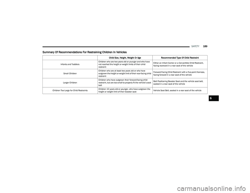
Summary Of Recommendations For Restraining Children In Vehicles
Child Size, Height, Weight Or Age Recommended Type Of Child Restraint
Infants and ToddlersChildren who are two years old or younger and who have
not reached the height or weight limits of their child
restraint Either an Infant Carrier or a Convertible Child Restraint,
facing rearward in a rear seat of the vehicle
Small Children Children who are at least two years old or who have
outgrown the height or weight limit of their rear-facing child
restraint Forward-Facing Child Restraint with a five-point Harness,
facing forward in a rear seat of the vehicle
Larger Children Children who have outgrown their forward-facing child
restraint, but are too small to properly fit the vehicle’s seat
belt Belt Positioning Booster Seat and the vehicle seat belt,
seated in a rear seat of the vehicle
Children Too Large for Child Restraints Children 12 years old or younger, who have outgrown the
height or weight limit of their booster seat Vehicle Seat Belt, seated in a rear seat of the vehicle
6
23_GG_OM_EN_USC_t.book Page 189