2023 DODGE CHARGER battery
[x] Cancel search: batteryPage 86 of 292
84STARTING AND OPERATING
NOTE:
Tapping one of the steering wheel-mounted shift
paddles (+/-), if equipped, while the gear selector is in
DRIVE, will activate a temporary AutoStick mode.
Tapping (-) to enter AutoStick mode will downshift the
transmission to the next lower gear, while tapping (+) to
enter AutoStick mode will retain the current gear. The
current gear will be displayed in the instrument cluster,
but the “M” will not be highlighted. The transmission
will revert back to normal operation (if the gear selector
remains in DRIVE) after a period of time, depending on
accelerator pedal activity.
In some models, the shift paddles may be disabled (or
re-enabled, as desired) using Drive Mode Set-Up,
accessed by selecting Performance Control.
In AutoStick mode, the transmission will shift up or down
when (+/-) is manually selected by the driver (using the
gear selector, or the shift paddles [if equipped]), unless an
engine lugging or overspeed condition would result. It will
remain in the selected gear until another upshift or
downshift is chosen, except as follows:
If normal AutoStick mode is engaged (gear selector in
MANUAL position), manual gear selection will be main -
tained until the gear selector is returned to DRIVE, or as
described in the following conditions. The transmission
will not upshift automatically at redline in this mode,
nor will downshifts be obtained if the accelerator pedal
is pressed to the floor.
The transmission will automatically downshift as the
vehicle slows (to prevent engine lugging) and will
display the current gear.
The transmission will automatically downshift to FIRST
gear when coming to a stop. After a stop, the driver
should manually upshift (+) the transmission as the
vehicle is accelerated.
You can start out, from a stop, in FIRST or SECOND
gear. Tapping (+) (at a stop) will allow starting in
SECOND gear. Starting out in SECOND gear can be
helpful in snowy or icy conditions.
If a requested downshift would cause the engine to
over-speed, that shift will not occur.
The system will ignore attempts to upshift at too low of
a vehicle speed and an indication will display.
Holding the (-) paddle pressed (if equipped), or holding
the gear selector in the (-) position, will downshift the
transmission to the lowest gear possible at the current
speed.
Transmission shifting will be more noticeable when
AutoStick is enabled.
The system may revert to automatic shift mode if a
fault or overheat condition is detected.
To disengage AutoStick mode, return the gear selector to
the DRIVE position, or press and hold the (+) shift paddle
(if equipped, and the gear selector is already in DRIVE)
until “D” is once again indicated in the instrument cluster.
You can shift in or out of the AutoStick mode at any time
without taking your foot off the accelerator pedal.SPORT MODE — WITHOUT PERFORMANCE
CONTROL
Your vehicle is equipped with a SPORT Mode feature. This
mode is a configuration set up for typical enthusiast
driving. The engine, transmission, and steering systems
are all set to their SPORT settings. SPORT Mode will
provide improved throttle response and modified shifting
for an enhanced driving experience, as well the greatest
amount of steering feel. This mode may be activated and
deactivated by pushing the Sport button on the instrument
panel switch bank.
For vehicles equipped with Drive Modes or a SUPER
TRACK PAK button, refer to Drive Modes Supplement for
further information.
FUEL SAVER TECHNOLOGY 5.7L ONLY— IF
EQUIPPED
This feature offers improved fuel economy by shutting off
four of the engine's eight cylinders during light load and
cruise conditions. The system is automatic with no driver
inputs or additional driving skills required.
NOTE:This system may take some time to return to full function -
ality after a battery disconnect.
WARNING!
Do not downshift for additional engine braking on a
slippery surface. The drive wheels could lose their grip
and the vehicle could skid, causing a collision or
personal injury.
23_LD_OM_EN_USC_t.book Page 84
Page 110 of 292
108STARTING AND OPERATING
The electrical connections are all complete to the vehicle
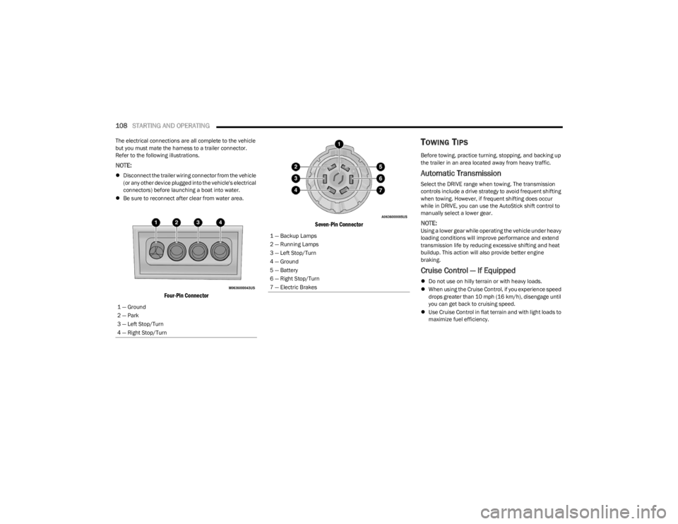
but you must mate the harness to a trailer connector.
Refer to the following illustrations.
NOTE:
Disconnect the trailer wiring connector from the vehicle
(or any other device plugged into the vehicle's electrical
connectors) before launching a boat into water.
Be sure to reconnect after clear from water area.
Four-Pin Connector Seven-Pin Connector
TOWING TIPS
Before towing, practice turning, stopping, and backing up
the trailer in an area located away from heavy traffic.
Automatic Transmission
Select the DRIVE range when towing. The transmission
controls include a drive strategy to avoid frequent shifting
when towing. However, if frequent shifting does occur
while in DRIVE, you can use the AutoStick shift control to
manually select a lower gear.
NOTE:Using a lower gear while operating the vehicle under heavy
loading conditions will improve performance and extend
transmission life by reducing excessive shifting and heat
buildup. This action will also provide better engine
braking.
Cruise Control — If Equipped
Do not use on hilly terrain or with heavy loads.
When using the Cruise Control, if you experience speed
drops greater than 10 mph (16 km/h), disengage until
you can get back to cruising speed.
Use Cruise Control in flat terrain and with light loads to
maximize fuel efficiency.
1 — Ground
2 — Park
3 — Left Stop/Turn
4 — Right Stop/Turn
1 — Backup Lamps
2 — Running Lamps
3 — Left Stop/Turn
4 — Ground
5 — Battery
6 — Right Stop/Turn
7 — Electric Brakes
23_LD_OM_EN_USC_t.book Page 108
Page 156 of 292

154MULTIMEDIA
3. After selecting a widget location, select the gauge to
display:
Gauge: Oil Temp
Gauge: Oil Pressure
Gauge: Coolant Temp
Gauge: Battery Voltage
Gauge: Trans Temp — If Equipped with an
Automatic Transmission
Gauge: Boost Pressure — If Equipped
Gauge: Air/Fuel Ratio — If Equipped
Gauge: I/C Coolant Temp — If Equipped
Gauge: Intake Air Temp
Gauge: Engine Torque
Gauge: Engine Power
Gauge: G-Force
Gauge: Steering Angle
Gauge: Current Gear
Gauge: Current Speed
Timer: 0–60 mph (0–100 km/h)
Timer: 0–100 mph (0–160 km/h)
Timer: 60 ft (20 m)
Timer: 330 ft (100 m)
Timer: 1/8 Mile (200 m)
Timer: 1000 ft (300 m)
Timer: 1/4 Mile (400 m)
Timer: Braking Distance
Timer: Reaction Time
Historical Data
The Historical Data feature allows you to view information
about your vehicle such as the VIN, miles on the odometer,
longitude and latitude coordinates, and more.
To activate the Historical Data feature on your
touchscreen, follow these steps:
1. Select the Home page tab within Performance Pages. Then, press the settings icon (gear icon) in
the upper right hand corner of the touchscreen.
Home Page Settings
2. Towards the bottom of the screen, a checkbox will appear next to “Include historical data in
screenshot.” Click the box to signify that this feature
will be on.
Historical Data
NOTE:
Once the checkbox is selected, the bottom bar of the
screen will be replaced with the historical data from your
vehicle present at the time the screenshot icon was
pressed.
23_LD_OM_EN_USC_t.book Page 154
Page 159 of 292
MULTIMEDIA157
GAUGES
Performance Pages — Gauges
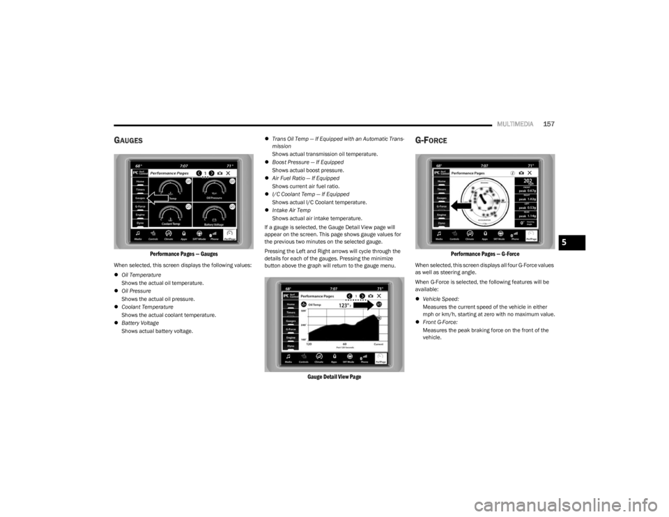
When selected, this screen displays the following values:
Oil Temperature
Shows the actual oil temperature.
Oil Pressure
Shows the actual oil pressure.
Coolant Temperature
Shows the actual coolant temperature.
Battery Voltage
Shows actual battery voltage.
Trans Oil Temp — If Equipped with an Automatic Trans -
mission
Shows actual transmission oil temperature.
Boost Pressure — If Equipped
Shows actual boost pressure.
Air Fuel Ratio — If Equipped
Shows current air fuel ratio.
I/C Coolant Temp — If Equipped
Shows actual I/C Coolant temperature.
Intake Air Temp
Shows actual air intake temperature.
If a gauge is selected, the Gauge Detail View page will
appear on the screen. This page shows gauge values for
the previous two minutes on the selected gauge.
Pressing the Left and Right arrows will cycle through the
details for each of the gauges. Pressing the minimize
button above the graph will return to the gauge menu.
Gauge Detail View Page
G-FORCE
Performance Pages — G-Force
When selected, this screen displays all four G-Force values
as well as steering angle.
When G-Force is selected, the following features will be
available:
Vehicle Speed:
Measures the current speed of the vehicle in either
mph or km/h, starting at zero with no maximum value.
Front G-Force:
Measures the peak braking force on the front of the
vehicle.
5
23_LD_OM_EN_USC_t.book Page 157
Page 185 of 292
SAFETY183
How To Engage The Automatic Locking Mode
1. Buckle the combination lap and shoulder belt.
2. Grab the shoulder portion and pull downward until
the entire seat belt is extracted.
3. Allow the seat belt to retract. As the seat belt retracts, you will hear a clicking sound. This indicates the seat
belt is now in the Automatic Locking Mode.
How To Disengage The Automatic Locking Mode
Unbuckle the combination lap/shoulder belt and allow it
to retract completely to disengage the Automatic Locking
Mode and activate the vehicle sensitive (emergency)
locking mode.
SUPPLEMENTAL RESTRAINT SYSTEMS
(SRS)
Some of the safety features described in this section may
be standard equipment on some models, or may be
optional equipment on others. If you are not sure, ask an
authorized dealer.
The air bag system must be ready to protect you in a
collision. The Occupant Restraint Controller (ORC)
monitors the internal circuits and interconnecting wiring
associated with the electrical Air Bag System Components. Your vehicle may be equipped with the
following Air Bag System Components:
Air Bag System Components
Occupant Restraint Controller (ORC)
Air Bag Warning Light
Steering Wheel and Column
Instrument Panel
Knee Impact Bolsters
Driver and Front Passenger Air Bags
Seat Belt Buckle Switch
Supplemental Side Air Bags
Supplemental Knee Air Bags
Front and Side Impact Sensors
Seat Belt Pretensioners
Seat Track Position Sensors
Air Bag Warning Light
The Occupant Restraint Controller (ORC)
monitors the readiness of the electronic parts
of the air bag system whenever the ignition
switch is in the START or ON/RUN position.
If the ignition switch is in the OFF position or in the ACC
position, the air bag system is not on and the air bags will
not inflate.
The ORC contains a backup power supply system that may
deploy the air bag system even if the battery loses power
or it becomes disconnected prior to deployment.
WARNING!
Never place a rear-facing child restraint in front of an
air bag. A deploying passenger front air bag can
cause death or serious injury to a child 12 years or
younger, including a child in a rear-facing child
restraint.
Never install a rear-facing child restraint in the front
seat of a vehicle. Only use a rear-facing child
restraint in the rear seat. If the vehicle does not have
a rear seat, do not transport a rear-facing child
restraint in that vehicle.
WARNING!
The seat belt assembly must be replaced if the
switchable Automatic Locking Retractor (ALR)
feature or any other seat belt function is not working
properly when checked according to the procedures
in the Service Manual.
Failure to replace the seat belt assembly could
increase the risk of injury in collisions.
Do not use the Automatic Locking Mode to restrain
occupants who are wearing the seat belt or children
who are using booster seats. The locked mode is only
used to install rear-facing or forward-facing child
restraints that have a harness for restraining the
child.
6
23_LD_OM_EN_USC_t.book Page 183
Page 190 of 292
188SAFETY
The Side Air Bags and seat belt pretensioners will not
deploy in all rollover events. The rollover sensing system
determines if a rollover event may be in progress and
whether deployment is appropriate. In the event the
vehicle experiences a rollover or near rollover event, and
deployment is appropriate, the rollover sensing system will
also deploy the side air bags and seat belt pretensioners
on both sides of the vehicle.
The SABICs may help reduce the risk of partial or complete
ejection of vehicle occupants through side windows in
certain rollover or side impact events.
Air Bag System Components
NOTE:The Occupant Restraint Controller (ORC) monitors the
internal circuits and interconnecting wiring associated
with electrical Air Bag System Components listed below:
Occupant Restraint Controller (ORC)
Air Bag Warning Light
Steering Wheel and Column
Instrument Panel
Knee Impact Bolsters
Driver and Front Passenger Air Bags
Seat Belt Buckle Switch
Supplemental Side Air Bags
Supplemental Knee Air Bags
Front and Side Impact Sensors
Seat Belt Pretensioners
Seat Track Position Sensors
If A Deployment Occurs
The front air bags are designed to deflate immediately
after deployment.
NOTE:Front and/or side air bags will not deploy in all collisions.
This does not mean something is wrong with the air bag
system.
If you do have a collision which deploys the air bags, any
or all of the following may occur:
The air bag material may sometimes cause abrasions
and/or skin reddening to the occupants as the air bags
deploy and unfold. The abrasions are similar to friction
rope burns or those you might get sliding along a carpet
or gymnasium floor. They are not caused by contact
with chemicals. They are not permanent and normally
heal quickly. However, if you haven’t healed signifi -
cantly within a few days, or if you have any blistering,
see your doctor immediately.
As the air bags deflate, you may see some smoke-like
particles. The particles are a normal by-product of the
process that generates the non-toxic gas used for air
bag inflation. These airborne particles may irritate the
skin, eyes, nose, or throat. If you have skin or eye irrita -
tion, rinse the area with cool water. For nose or throat
irritation, move to fresh air. If the irritation continues,
see your doctor. If these particles settle on your
clothing, follow the garment manufacturer’s instruc -
tions for cleaning. Do not drive your vehicle after the air bags have deployed.
If you are involved in another collision, the air bags will not
be in place to protect you.
NOTE:
Air bag covers may not be obvious in the interior trim,
but they will open during air bag deployment.
After any collision, the vehicle should be taken to an
authorized dealer immediately.
Enhanced Accident Response System
In the event of an impact, if the communication network
remains intact, and the power remains intact, depending
on the nature of the event, the Occupant Restraint
Controller (ORC) will determine whether to have the
Enhanced Accident Response System perform the
following functions:
Cut off fuel to the engine (if equipped).
Cut off battery power to the electric motor (if equipped).
Flash hazard lights as long as the battery has power.
Turn on the interior lights, which remain on as long as
the battery has power or for 15 minutes from the inter -
vention of the Enhanced Accident Response System.
Unlock the power door locks.
WARNING!
Deployed air bags and seat belt pretensioners cannot
protect you in another collision. Have the air bags, seat
belt pretensioners, and the seat belt retractor
assemblies replaced by an authorized dealer
immediately. Also, have the Occupant Restraint
Controller System serviced as well.
23_LD_OM_EN_USC_t.book Page 188
Page 191 of 292

SAFETY189
(Continued)
Your vehicle may also be designed to perform any of these
other functions in response to the Enhanced Accident
Response System:
Turn off the Fuel Filter Heater, Turn off the HVAC Blower
Motor, Close the HVAC Circulation Door
Cut off battery power to the:
Engine
Electric Motor (if equipped)
Electric power steering
Brake booster
Electric park brake
Automatic transmission gear selector
Horn
Front wiper
NOTE:After an accident, remember to cycle the ignition to the
STOP (OFF/LOCK) position and remove the key from the
ignition switch to avoid draining the battery. Carefully
check the vehicle for fuel leaks in the engine compartment
and on the ground near the engine compartment and fuel
tank before resetting the system and starting the engine.
If there are no fuel leaks or damage to the vehicle elec -
trical devices (e.g. headlights) after an accident, reset the
system by following the procedure described below. If you
have any doubt, contact an authorized dealer.
Enhanced Accident Response System
Reset Procedure
In order to reset the Enhanced Accident Response System
functions after an event, the ignition switch must be
changed from ignition START or ON/RUN to ignition OFF.
Carefully check the vehicle for fuel leaks in the engine
compartment and on the ground near the engine
compartment and fuel tank before resetting the system
and starting the engine.
After an accident, if the vehicle will not start after
performing the reset procedure, the vehicle must be
towed to an authorized dealer to be inspected and to have
the Enhanced Accident Response System reset.
Maintaining Your Air Bag System Event Data Recorder (EDR)
This vehicle is equipped with an event data recorder
(EDR). The main purpose of an EDR is to record, in certain
crash or near crash-like situations, such as an air bag
deployment or hitting a road obstacle, data that will assist
in understanding how a vehicle’s systems performed. The
EDR is designed to record data related to vehicle
dynamics and safety systems for a short period of time,
typically 30 seconds or less. The EDR in this vehicle is
designed to record such data as:
How various systems in your vehicle were operating;
Whether or not the driver and passenger safety belts
were buckled/fastened;
How far (if at all) the driver was depressing the acceler -
ator and/or brake pedal; and,
How fast the vehicle was traveling.WARNING!
Modifications to any part of the air bag system could
cause it to fail when you need it. You could be injured
if the air bag system is not there to protect you. Do
not modify the components or wiring, including
adding any kind of badges or stickers to the steering
wheel hub trim cover or the upper passenger side of
the instrument panel. Do not modify the front fascia/
bumper, vehicle body structure, or add aftermarket
side steps or running boards.
It is dangerous to try to repair any part of the air bag
system yourself. Be sure to tell anyone who works on
your vehicle that it has an air bag system.
Do not attempt to modify any part of your air bag
system. The air bag may inflate accidentally or may
not function properly if modifications are made. Take
your vehicle to an authorized dealer for any air bag
system service. If your seat, including your trim cover
and cushion, needs to be serviced in any way
(including removal or loosening/tightening of seat
attachment bolts), take the vehicle to an authorized
dealer. Only manufacturer approved seat accesso -
ries may be used. If it is necessary to modify the air
bag system for persons with disabilities, contact an
authorized dealer.
WARNING!
6
23_LD_OM_EN_USC_t.book Page 189
Page 204 of 292
202
IN CASE OF EMERGENCY
HAZARD WARNING FLASHERS
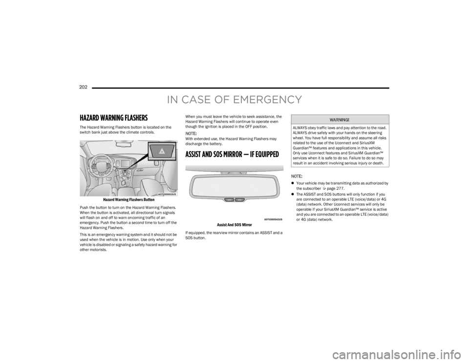
The Hazard Warning Flashers button is located on the
switch bank just above the climate controls.
Hazard Warning Flashers Button
Push the button to turn on the Hazard Warning Flashers.
When the button is activated, all directional turn signals
will flash on and off to warn oncoming traffic of an
emergency. Push the button a second time to turn off the
Hazard Warning Flashers.
This is an emergency warning system and it should not be
used when the vehicle is in motion. Use only when your
vehicle is disabled or signaling a safety hazard warning for
other motorists.When you must leave the vehicle to seek assistance, the
Hazard Warning Flashers will continue to operate even
though the ignition is placed in the OFF position.
NOTE:With extended use, the Hazard Warning Flashers may
discharge the battery.
ASSIST AND SOS MIRROR — IF EQUIPPED
Assist And SOS Mirror
If equipped, the rearview mirror contains an ASSIST and a
SOS button.
NOTE:
Your vehicle may be transmitting data as authorized by
the subscriber Úpage 277.
The ASSIST and SOS buttons will only function if you
are connected to an operable LTE (voice/data) or 4G
(data) network. Other Uconnect services will only be
operable if your SiriusXM Guardian™ service is active
and you are connected to an operable LTE (voice/data)
or 4G (data) network.
WARNING!
ALWAYS obey traffic laws and pay attention to the road.
ALWAYS drive safely with your hands on the steering
wheel. You have full responsibility and assume all risks
related to the use of the Uconnect and SiriusXM
Guardian™ features and applications in this vehicle.
Only use Uconnect features and SiriusXM Guardian™
services when it is safe to do so. Failure to do so may
result in an accident involving serious injury or death.
23_LD_OM_EN_USC_t.book Page 202