2023 DODGE CHALLENGER tire pressure
[x] Cancel search: tire pressurePage 240 of 300
238SERVICING AND MAINTENANCE
Coolant Checks
Check engine coolant (antifreeze) protection every
12 months (before the onset of freezing weather, where
applicable). If the engine coolant is dirty, the system
should be drained, flushed, and refilled with fresh Organic
Additive Technology (OAT) coolant (conforming to
MS.90032) by an authorized dealer. Check the front of the
radiator for any accumulation of bugs, leaves, etc. If dirty,
clean by gently spraying water from a garden hose
vertically down the face of the condenser.
Check the coolant recovery bottle tubing for brittle rubber,
cracking, tears, cuts, and tightness of the connection at
the bottle and radiator. Inspect the entire system for
leaks. DO NOT REMOVE THE COOLANT PRESSURE CAP
WHEN THE COOLING SYSTEM IS HOT.
Cooling System — Drain, Flush And Refill
NOTE:Some vehicles require special tools to add coolant
properly. Failure to fill these systems properly could lead
to severe internal engine damage. If any coolant is needed
to be added to the system please contact an authorized
dealer.
If the engine coolant (antifreeze) is dirty or contains visible
sediment, have an authorized dealer clean and flush with
Organic Additive Technology (OAT) coolant (conforming to
MS.90032).
For the proper maintenance intervals
Úpage 224.
Selection Of Coolant
For further information Úpage 278.
NOTE:
Mixing of engine coolant (antifreeze) other than speci-
fied Organic Additive Technology (OAT) engine coolant,
may result in engine damage and may decrease corro -
sion protection. OAT engine coolant is different and
should not be mixed with Hybrid Organic Additive Tech -
nology (HOAT) engine coolant or any “globally compat -
ible” coolant. If a non-OAT engine coolant is introduced
into the cooling system in an emergency, the cooling
system will need to be drained, flushed, and refilled
with fresh OAT coolant (conforming to MS.90032), by
an authorized dealer as soon as possible.
Do not use water alone or alcohol-based engine
coolant products. Do not use additional rust inhibitors
or antirust products, as they may not be compatible
with the radiator engine coolant and may plug the radi -
ator.
This vehicle has not been designed for use with
propylene glycol-based engine coolant. Use of
propylene glycol-based engine coolant is not recom -
mended.
Some vehicles require special tools to add coolant
properly. Failure to fill these systems properly could
lead to severe internal engine damage. If any coolant is
needed to be added to the system please contact an
authorized dealer.
Adding Coolant
Your vehicle has been built with an improved engine
coolant (OAT coolant conforming to MS.90032) that
allows extended maintenance intervals. This engine
coolant (antifreeze) can be used up to 10 years or
150,000 miles (240,000 km) before replacement. To
prevent reducing this extended maintenance period, it is
important to use the same engine coolant (OAT coolant
conforming to MS.90032) throughout the life of your
vehicle.
Please review these recommendations for using Organic
Additive Technology (OAT) engine coolant that meets the
requirements of the manufacturer Material Standard
MS.90032. When adding engine coolant:
We recommend using Mopar® Antifreeze/Coolant
10 Year/150,000 Mile (240,000 km) Formula OAT
that meets the requirements of the manufacturer
Material Standard MS.90032.
Mix a minimum solution of 50% OAT engine coolant
that meets the requirements of the manufacturer
Material Standard MS.90032 and distilled water.
Use higher concentrations (not to exceed 70%) if
temperatures below −34°F (−37°C) are anticipated.
Please contact an authorized dealer for assistance.
Use only high purity water such as distilled or deionized
water when mixing the water/engine coolant solution.
The use of lower quality water will reduce the amount
of corrosion protection in the engine cooling system.
23_LA_OM_EN_USC_t.book Page 238
Page 249 of 300
SERVICING AND MAINTENANCE247
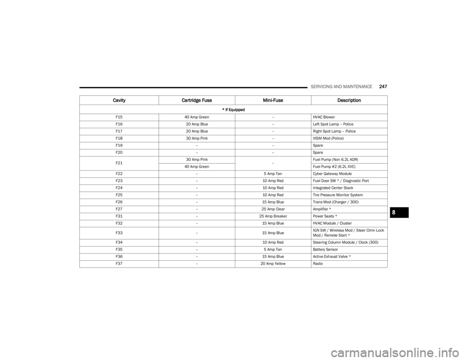
F15 40 Amp Green –HVAC Blower
F16 20 Amp Blue –Left Spot Lamp – Police
F17 20 Amp Blue –Right Spot Lamp – Police
F18 30 Amp Pink –VISM Mod (Police)
F19 ––Spare
F20 ––Spare
F21 30 Amp Pink
–Fuel Pump (Non 6.2L ADR)
40 Amp Green Fuel Pump #2 (6.2L XVC)
F22 –5 Amp TanCyber Gateway Module
F23 –10 Amp RedFuel Door SW * / Diagnostic Port
F24 –10 Amp RedIntegrated Center Stack
F25 –10 Amp RedTire Pressure Monitor System
F26 –15 Amp BlueTrans Mod (Charger / 300)
F27 –25 Amp ClearAmplifier *
F31 –25 Amp BreakerPower Seats *
F32 –15 Amp BlueHVAC Module / Cluster
F33 –15 Amp BlueIGN SW / Wireless Mod / Steer Clmn Lock
Mod / Remote Start *
F34 –10 Amp RedSteering Column Module / Clock (300)
F35 –5 Amp TanBattery Sensor
F36 –15 Amp BlueActive Exhaust Valve *
F37 –20 Amp YellowRadio
Cavity Cartridge Fuse Mini-FuseDescription
* If Equipped
8
23_LA_OM_EN_USC_t.book Page 247
Page 255 of 300

SERVICING AND MAINTENANCE253
LOW BEAM HEADLAMP, HIGH BEAM HEAD -
LAMP — MODELS WITH HIGH INTENSITY
DISCHARGE (HID) HEADLAMPS — IF EQUIPPED
The headlamps are a type of high voltage discharge tube.
High voltage can remain in the circuit even with the
headlamp switch off and the key removed. Because of
this, you should not attempt to service a headlamp bulb
yourself. If a headlamp bulb fails, take your vehicle to an
authorized dealer for service.
NOTE:On vehicles equipped with HID headlamps, when the
headlamps are turned on, there is a blue hue to the lamps.
This diminishes and becomes more white after approxi -
mately 10 seconds, as the system charges.
FRONT PARK/SIGNATURE LAMP
The Front Park/Signature function is part of the headlamp
assembly and use LED lamps that are not serviceable
separately. The headlamps must be replaced as an
assembly, see an authorized dealer.
FRONT TURN/DRL LAMP
The Front Turn/DRL function is part of the headlamp
assembly and use LED lamps that are not serviceable
separately. The headlamps must be replaced as an
assembly, see an authorized dealer.
FRONT/REAR SIDE MARKER LAMP
The Side Markers use LED lamps that are not serviceable
separately. The Side Markers must be replaced as an
assembly, see an authorized dealer.
TAIL/TURN AND STOP LAMP
The Tail/Turn and Stop Lamps use LED lamps that are not
serviceable separately. The Tail/Turn and Stop Lamps
must be replaced as an assembly, see an authorized
dealer.
CENTER TAIL/BACKUP LAMP
The Center Tail/Backup Lamp use LED lamps that are not
serviceable separately. The Center Tail/Backup Lamp
must be replaced as an assembly; see an authorized
dealer.
CENTER HIGH MOUNTED STOP LAMP (CHMSL)
The CHMSL Lamp uses LED sources that are not
serviceable separately. The CHMSL Lamp must be
replaced as an assembly; see an authorized dealer.
LICENSE LAMP
The License Lamp uses an LED source that is not
serviceable separately. The License Lamp must be
replaced as an assembly; see an authorized dealer.
TIRES
TIRE SAFETY INFORMATION
Tire safety information will cover aspects of the following
information: Tire Markings, Tire Identification Numbers,
Tire Terminology and Definitions, Tire Pressures, and Tire
Loading.
WARNING!
A transient high voltage occurs at the bulb sockets of
HID headlamps when the headlamp switch is turned
ON. It may cause serious electrical shock or
electrocution if not serviced properly. See an authorized
dealer for service.
8
23_LA_OM_EN_USC_t.book Page 253
Page 256 of 300

254SERVICING AND MAINTENANCE
Tire Markings
Tire Markings
NOTE:
P (Passenger) — Metric tire sizing is based on US design
standards. P-Metric tires have the letter “P” molded
into the sidewall preceding the size designation.
Example: P215/65R15 95H.
European — Metric tire sizing is based on European
design standards. Tires designed to this standard have
the tire size molded into the sidewall beginning with the
section width. The letter "P" is absent from this tire size
designation.
Example: 215/65R15 96H.
LT (Light Truck) — Metric tire sizing is based on US
design standards. The size designation for LT-Metric
tires is the same as for P-Metric tires except for the
letters “LT” that are molded into the sidewall preceding
the size designation.
Example: LT235/85R16.
Temporary spare tires are designed for temporary
emergency use only. Temporary high pressure compact
spare tires have the letter “T” or “S” molded into the
sidewall preceding the size designation.
Example: T145/80D18 103M.
High flotation tire sizing is based on US design stan -
dards and it begins with the tire diameter molded into
the sidewall.
Example: 31x10.5 R15 LT.
1 — US DOT Safety Standards Code
(TIN)
2 — Size Designation
3 — Service Description
4 — Maximum Load
5 — Maximum Pressure
6 — Treadwear, Traction and
Temperature Grades
23_LA_OM_EN_USC_t.book Page 254
Page 258 of 300
256SERVICING AND MAINTENANCE
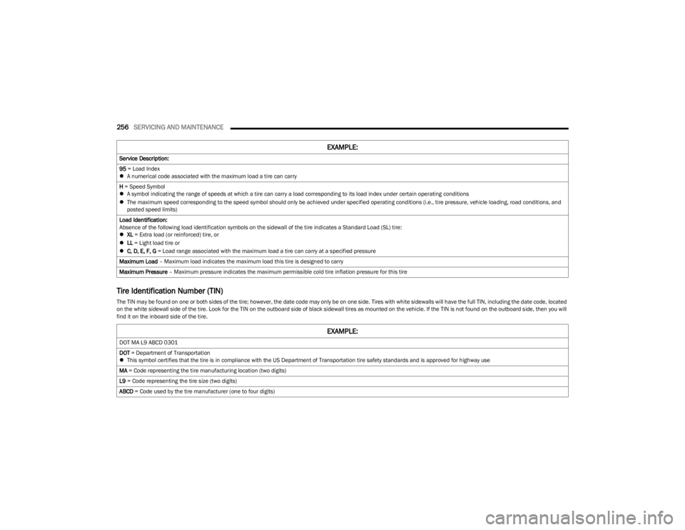
Tire Identification Number (TIN)
The TIN may be found on one or both sides of the tire; however, the date code may only be on one side. Tires with white sidewalls will have the full TIN, including the date code, located
on the white sidewall side of the tire. Look for the TIN on the outboard side of black sidewall tires as mounted on the vehicle. If the TIN is not found on the outboard side, then you will
find it on the inboard side of the tire.Service Description:
95
= Load Index
A numerical code associated with the maximum load a tire can carry
H = Speed Symbol
A symbol indicating the range of speeds at which a tire can carry a load corresponding to its load index under certain operating conditions
The maximum speed corresponding to the speed symbol should only be achieved under specified operating conditions (i.e., tire pressure, vehicle loading, road conditions, and
posted speed limits)
Load Identification:
Absence of the following load identification symbols on the sidewall of the tire indicates a Standard Load (SL) tire:
XL = Extra load (or reinforced) tire, or
LL = Light load tire or
C, D, E, F, G = Load range associated with the maximum load a tire can carry at a specified pressure
Maximum Load – Maximum load indicates the maximum load this tire is designed to carry
Maximum Pressure – Maximum pressure indicates the maximum permissible cold tire inflation pressure for this tire
EXAMPLE:
EXAMPLE:
DOT MA L9 ABCD 0301
DOT = Department of Transportation
This symbol certifies that the tire is in compliance with the US Department of Transportation tire safety standards and is approved for highway use
MA = Code representing the tire manufacturing location (two digits)
L9 = Code representing the tire size (two digits)
ABCD = Code used by the tire manufacturer (one to four digits)
23_LA_OM_EN_USC_t.book Page 256
Page 259 of 300
SERVICING AND MAINTENANCE257
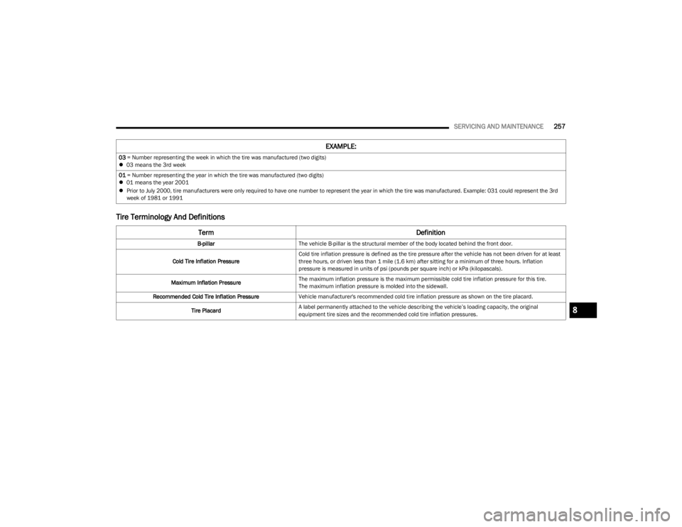
Tire Terminology And Definitions
03 = Number representing the week in which the tire was manufactured (two digits)
03 means the 3rd week
01 = Number representing the year in which the tire was manufactured (two digits)
01 means the year 2001
Prior to July 2000, tire manufacturers were only required to have one number to represent the year in which the tire was manufactured. Example: 031 could represent the 3rd
week of 1981 or 1991
Term Definition
B-pillarThe vehicle B-pillar is the structural member of the body located behind the front door.
Cold Tire Inflation Pressure Cold tire inflation pressure is defined as the tire pressure after the vehicle has not been driven for at least
three hours, or driven less than 1 mile (1.6 km) after sitting for a minimum of three hours. Inflation
pressure is measured in units of psi (pounds per square inch) or kPa (kilopascals).
Maximum Inflation Pressure The maximum inflation pressure is the maximum permissible cold tire inflation pressure for this tire.
The maximum inflation pressure is molded into the sidewall.
Recommended Cold Tire Inflation Pressure Vehicle manufacturer's recommended cold tire inflation pressure as shown on the tire placard.
Tire Placard A label permanently attached to the vehicle describing the vehicle’s loading capacity, the original
equipment tire sizes and the recommended cold tire inflation pressures.
EXAMPLE:
8
23_LA_OM_EN_USC_t.book Page 257
Page 260 of 300
258SERVICING AND MAINTENANCE
Tire Loading And Tire Pressure
NOTE:The proper cold tire inflation pressure is listed on the
driver’s side B-pillar or the rear edge of the driver's side
door.
Check the inflation pressure of each tire, including the
spare tire (if equipped), at least monthly and inflate to the
recommended pressure for your vehicle.
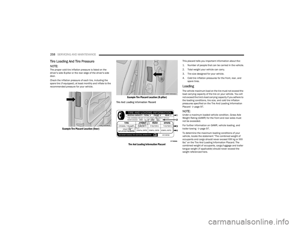
Example Tire Placard Location (Door) Example Tire Placard Location (B-pillar)
Tire And Loading Information Placard
Tire And Loading Information Placard
This placard tells you important information about the:
1. Number of people that can be carried in the vehicle.
2. Total weight your vehicle can carry.
3. Tire size designed for your vehicle.
4. Cold tire inflation pressures for the front, rear, and
spare tires.
Loading
The vehicle maximum load on the tire must not exceed the
load carrying capacity of the tire on your vehicle. You will
not exceed the tire's load carrying capacity if you adhere to
the loading conditions, tire size, and cold tire inflation
pressures specified on the Tire And Loading Information
Placard
Úpage 97.
NOTE:Under a maximum loaded vehicle condition, Gross Axle
Weight Rating (GAWR) for the front and rear axles must
not be exceeded.
For further information on GAWR, vehicle loading, and
trailer towing
Úpage 97.
To determine the maximum loading conditions of your
vehicle, locate the statement “The combined weight of
occupants and cargo should never exceed XXX kg or XXX
lbs” on the Tire And Loading Information Placard. The
combined weight of occupants, cargo/luggage and trailer
tongue weight (if applicable) should never exceed the
weight referenced here.
23_LA_OM_EN_USC_t.book Page 258
Page 263 of 300

SERVICING AND MAINTENANCE261
(Continued)
TIRES — GENERAL INFORMATION
Tire Pressure
Proper tire inflation pressure is essential to the safe and
satisfactory operation of your vehicle. Four primary areas
are affected by improper tire pressure:
Safety
Fuel Economy
Tread Wear
Ride Comfort and Vehicle Stability
Safety Both underinflation and overinflation affect the stability of
the vehicle and can produce a feeling of sluggish response
or over responsiveness in the steering.
NOTE:
Unequal tire pressures from side to side may cause
erratic and unpredictable steering response.
Unequal tire pressure from side to side may cause the
vehicle to drift left or right.
Fuel Economy
Underinflated tires will increase tire rolling resistance
resulting in higher fuel consumption.
Tread Wear
Improper cold tire inflation pressures can cause abnormal
wear patterns and reduced tread life, resulting in the need
for earlier tire replacement. Ride Comfort And Vehicle Stability
Proper tire inflation contributes to a comfortable ride.
Overinflation produces a jarring and uncomfortable ride.
Tire Inflation Pressures
The proper cold tire inflation pressure is listed on the
driver's side B-pillar or rear edge of the driver's side door.
At least once a month:
Check and adjust tire pressure with a good quality
pocket-type pressure gauge. Do not make a visual judg -
ment when determining proper inflation. Tires may look
properly inflated even when they are underinflated.
Inspect tires for signs of tire wear or visible damage.
Inflation pressures specified on the placard are always
“cold tire inflation pressure”. Cold tire inflation pressure is
defined as the tire pressure after the vehicle has not been
driven for at least 3 hours, or driven less than 1 mile
(1.6 km) after sitting for a minimum of 3 hours. The cold
tire inflation pressure must not exceed the maximum
inflation pressure molded into the tire sidewall.
WARNING!
Overloading of your tires is dangerous. Overloading can
cause tire failure, affect vehicle handling, and increase
your stopping distance. Use tires of the recommended
load capacity for your vehicle. Never overload them.
WARNING!
Improperly inflated tires are dangerous and can
cause collisions.
Underinflation increases tire flexing and can result in
overheating and tire failure.
Overinflation reduces a tire's ability to cushion shock.
Objects on the road and chuckholes can cause
damage that result in tire failure.
Overinflated or underinflated tires can affect vehicle
handling and can fail suddenly, resulting in loss of
vehicle control.
Unequal tire pressures can cause steering problems.
You could lose control of your vehicle.
Unequal tire pressures from one side of the vehicle
to the other can cause the vehicle to drift to the right
or left.
Always drive with each tire inflated to the recom -
mended cold tire inflation pressure.
WARNING!
CAUTION!
After inspecting or adjusting the tire pressure, always
reinstall the valve stem cap. This will prevent moisture
and dirt from entering the valve stem, which could
damage the valve stem.
8
23_LA_OM_EN_USC_t.book Page 261