2023 CHRYSLER PACIFICA center console
[x] Cancel search: center consolePage 51 of 328

GETTING TO KNOW YOUR VEHICLE49
OUTSIDE MIRRORS
The outside mirror(s) can be adjusted to the center of the
adjacent lane of traffic to achieve the optimal view.
OUTSIDE MIRRORS WITH TURN SIGNAL —
I
F EQUIPPED
Driver and passenger outside mirrors with turn signal
lighting contain LEDs, which are located in the upper outer
corner of each mirror.
The LEDs are turn signal indicators, which flash with the
corresponding turn signal lights in the front and rear of the
vehicle. Turning on the Hazard Warning flashers will also
activate these LEDs.
DRIVER'S OUTSIDE AUTOMATIC
D
IMMING MIRROR — IF EQUIPPED
The driver’s outside mirror will automatically adjust for
glare from vehicles behind you. This feature is controlled
by the inside automatic dimming mirror and will
automatically adjust for headlight glare when the inside
mirror adjusts.
CONVERSATION MIRROR
Located in the overhead console there is a conversation
mirror to view all the passengers in the vehicle. Push the
panel to release the drop down mirror. Raise the mirror
and push to latch it back in the stowed position.
Conversation Mirror
POWER MIRRORS — IF EQUIPPED
The power mirror controls are located on the driver-side
door trim panel.
Power Mirror Controls
The power mirror controls consist of mirror select buttons
and a four-way mirror control switch. To adjust a mirror,
push either the L (left) or R (right) to select the mirror that
you want to adjust.
NOTE:A light in the selected button will illuminate indicating the
mirror is activated and can be adjusted.
Using the mirror control switch, push on any of the four
arrows for the direction that you want the mirror to move.
Left and Right side power mirror positions can be saved as
part of the driver memory profile (if equipped)
Úpage 27.
WARNING!
Vehicles and other objects seen in an outside convex
mirror will look smaller and farther away than they
really are. Relying too much on side convex mirrors
could cause you to collide with another vehicle or other
object. Use your inside mirror when judging the size or
distance of a vehicle seen in a side convex mirror.
1 — Left Mirror Select
2 — Mirror Control Switch
3 — Right Mirror Select
2
23_RUP_OM_EN_USC_t.book Page 49
Page 53 of 328

GETTING TO KNOW YOUR VEHICLE51
TILT SIDE MIRRORS IN REVERSE —
I
F EQUIPPED
Tilt Side Mirrors In Reverse provides automatic outside
mirror positioning which will aid the driver’s view of the
ground rearward of the front doors. The driver's outside
mirror will move slightly downward from the present
position when the vehicle is shifted into REVERSE. The
driver's outside mirror will then return to the original
position when the vehicle is shifted out of the REVERSE
position. Each stored memory setting will have an
associated Tilt Side Mirrors In Reverse position.
NOTE:The Tilt Side Mirrors In Reverse feature can be enabled or
disabled through the Uconnect system Úpage 157.
UNIVERSAL GARAGE DOOR OPENER
(HOMELINK®) — IF EQUIPPED
HomeLink® Buttons And Indicator Light
Use this QR code to access your digital
experience.
HomeLink® replaces up to three
hand-held transmitters that operate
devices such as garage door
openers, motorized gates, lighting,
or home security systems. The
HomeLink® unit is powered by your
vehicle’s 12 Volt battery.
The HomeLink® buttons that are located in the over -
head console or sun visor designate the three different
HomeLink® channels.
To operate HomeLink®, push and release any of the
programmed HomeLink® buttons. These buttons will
activate the devices they are programmed to with each
press of the corresponding HomeLink® button.
The HomeLink® indicator light is located above the
center button.
NOTE:HomeLink® is disabled when the Vehicle Security system
is active Úpage 312.
BEFORE YOU BEGIN PROGRAMMING
H
OMELINK®
For efficient programming and accurate transmission of
the Radio Frequency (RF) signal, it is recommended that a
new battery be placed in the hand-held transmitter of the
device that is being programmed to the HomeLink®
system. Make sure your hand-held transmitter is
programmed to activate the device you are trying to
program your HomeLink® button to.
Ensure that your vehicle is parked outside of the garage
before you begin programming.
It is recommended that you erase all the channels of your
HomeLink® before you use it for the first time.
ERASING ALL THE HOMELINK®
C
HANNELS
To erase the channels, follow this procedure:
1. Place the ignition switch into the ON/RUN position.
2. Push and hold the two outside HomeLink® buttons
(I and III) for up to 20 seconds, or until the
HomeLink® indicator light flashes.
NOTE:Erasing all channels should only be performed when
programming HomeLink® for the first time. Do not erase
channels when programming additional buttons.
2
23_RUP_OM_EN_USC_t.book Page 51
Page 74 of 328
72GETTING TO KNOW YOUR VEHICLE
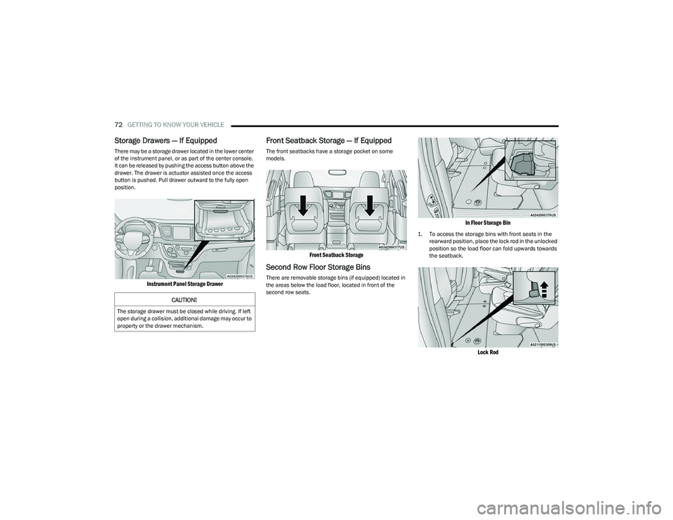
Storage Drawers — If Equipped
There may be a storage drawer located in the lower center
of the instrument panel, or as part of the center console.
It can be released by pushing the access button above the
drawer. The drawer is actuator assisted once the access
button is pushed. Pull drawer outward to the fully open
position.
Instrument Panel Storage Drawer
Front Seatback Storage — If Equipped
The front seatbacks have a storage pocket on some
models.
Front Seatback Storage
Second Row Floor Storage Bins
There are removable storage bins (if equipped) located in
the areas below the load floor, located in front of the
second row seats.
In Floor Storage Bin
1. To access the storage bins with front seats in the
rearward position, place the lock rod in the unlocked
position so the load floor can fold upwards towards
the seatback.
Lock Rod
CAUTION!
The storage drawer must be closed while driving. If left
open during a collision, additional damage may occur to
property or the drawer mechanism.
23_RUP_OM_EN_USC_t.book Page 72
Page 76 of 328
74GETTING TO KNOW YOUR VEHICLE
LIGHTED CUPHOLDERS — IF EQUIPPED
On some vehicles, the front cupholders are equipped with
a light ring that illuminates the cupholders for the front
passengers. The light ring is controlled by the Dimmer
Controls
Úpage 58.
SUN SCREENS — IF EQUIPPED
Sun screens are available for second and third row seating
windows. The screens store in the sill trim panels, and the
tops of the windows are equipped with hooks that the sun
screens attach to when pulled out.
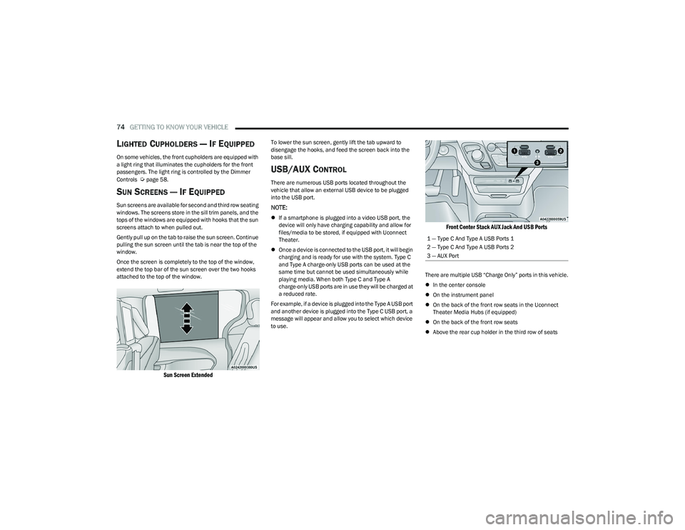
Gently pull up on the tab to raise the sun screen. Continue
pulling the sun screen until the tab is near the top of the
window.
Once the screen is completely to the top of the window,
extend the top bar of the sun screen over the two hooks
attached to the top of the window.
Sun Screen Extended
To lower the sun screen, gently lift the tab upward to
disengage the hooks, and feed the screen back into the
base sill.
USB/AUX CONTROL
There are numerous USB ports located throughout the
vehicle that allow an external USB device to be plugged
into the USB port.
NOTE:
If a smartphone is plugged into a video USB port, the
device will only have charging capability and allow for
files/media to be stored, if equipped with Uconnect
Theater.
Once a device is connected to the USB port, it will begin
charging and is ready for use with the system. Type C
and Type A charge-only USB ports can be used at the
same time but cannot be used simultaneously while
playing media. When both Type C and Type A
charge-only USB ports are in use they will be charged at
a reduced rate.
For example, if a device is plugged into the Type A USB port
and another device is plugged into the Type C USB port, a
message will appear and allow you to select which device
to use.
Front Center Stack AUX Jack And USB Ports
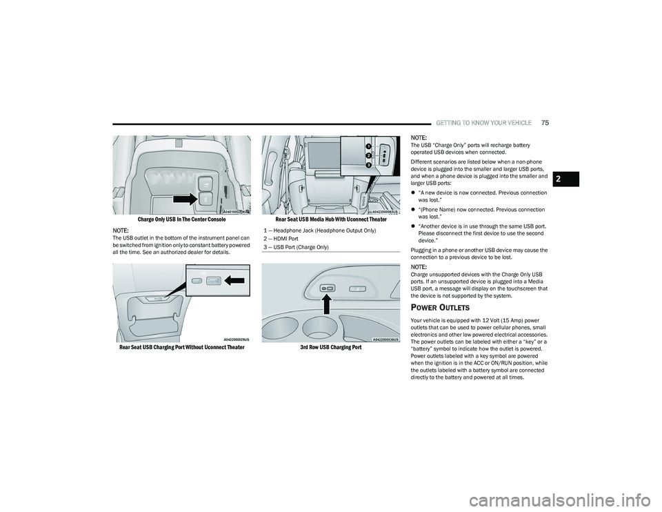
There are multiple USB “Charge Only” ports in this vehicle.
In the center console
On the instrument panel
On the back of the front row seats in the Uconnect
Theater Media Hubs (if equipped)
On the back of the front row seats
Above the rear cup holder in the third row of seats
1 — Type C And Type A USB Ports 1
2 — Type C And Type A USB Ports 2
3 — AUX Port
23_RUP_OM_EN_USC_t.book Page 74
Page 77 of 328
GETTING TO KNOW YOUR VEHICLE75
Charge Only USB In The Center Console
NOTE:
The USB outlet in the bottom of the instrument panel can
be switched from ignition only to constant battery powered
all the time. See an authorized dealer for details.
Rear Seat USB Charging Port Without Uconnect Theater Rear Seat USB Media Hub With Uconnect Theater
3rd Row USB Charging Port
NOTE:
The USB “Charge Only” ports will recharge battery
operated USB devices when connected.
Different scenarios are listed below when a non-phone
device is plugged into the smaller and larger USB ports,
and when a phone device is plugged into the smaller and
larger USB ports:
“A new device is now connected. Previous connection
was lost.”
“(Phone Name) now connected. Previous connection
was lost.”
“Another device is in use through the same USB port.
Please disconnect the first device to use the second
device.”
Plugging in a phone or another USB device may cause the
connection to a previous device to be lost.
NOTE:Charge unsupported devices with the Charge Only USB
ports. If an unsupported device is plugged into a Media
USB port, a message will display on the touchscreen that
the device is not supported by the system.
POWER OUTLETS
Your vehicle is equipped with 12 Volt (15 Amp) power
outlets that can be used to power cellular phones, small
electronics and other low powered electrical accessories.
The power outlets can be labeled with either a “key” or a
“battery” symbol to indicate how the outlet is powered.
Power outlets labeled with a key symbol are powered
when the ignition is in the ACC or ON/RUN position, while
the outlets labeled with a battery symbol are connected
directly to the battery and powered at all times.
1 — Headphone Jack (Headphone Output Only)
2 — HDMI Port
3 — USB Port (Charge Only)
2
23_RUP_OM_EN_USC_t.book Page 75
Page 78 of 328

76GETTING TO KNOW YOUR VEHICLE
NOTE:All accessories connected to the battery powered outlets
should be removed or turned off when the vehicle is not in
use to protect the battery against discharge.
Depending on the type of center console your vehicle is
equipped with, there is a front power outlet located either
on the bottom of the instrument panel or inside the center
console.
12 Volt Front Power Outlet (In Floor Tray) - If Equipped 12 Volt Front Power Outlet (In Center Console)
In addition to the front power outlet, there is also a power
outlet located in the rear cargo area.
The rear power outlet is located in the right rear cargo
area.
Rear Power Outlet
NOTE:
The front power outlet can be changed to battery powered at
all times by switching the power outlet fuse in the Power
Distribution Center panel from fuse location F95A to F95B.
Power Outlet Fuse Locations
CAUTION!
Power outlets are designed for accessory plugs only. Do
not insert any other object in the power outlets as this
will damage the outlet and blow the fuse. Improper use
of the power outlet can cause damage not covered by
your New Vehicle Limited Warranty.
1 — F95A (Ignition)/F95B (Battery) Front Power Outlet 10A
2 — F85 Cigar Lighter 20A
3 — F60 RR Cargo Power Outlet 20A
WARNING!
To avoid serious injury or death:
Only devices designed for use in this type of outlet
should be inserted into any 12 Volt outlet.
Do not touch with wet hands.
Close the lid when not in use and while driving the vehicle.
If this outlet is mishandled, it may cause an electric
shock and failure.
23_RUP_OM_EN_USC_t.book Page 76
Page 120 of 328
118STARTING AND OPERATING
IGNITION PARK INTERLOCK
This vehicle is equipped with an Ignition Park Interlock
which requires the transmission to be in PARK before the
ignition can be turned to the OFF position. This helps the
driver avoid inadvertently leaving the vehicle without
placing the transmission in PARK. This system also locks
the transmission in PARK whenever the ignition is in the
OFF position.
NOTE:The transmission is NOT locked in PARK when the ignition
is in the ACC position (even though the engine will be off).
Ensure that the transmission is in PARK, and the ignition
is OFF (not in ACC position) before exiting the vehicle.
BRAKE/TRANSMISSION SHIFT
I
NTERLOCK (BTSI) SYSTEM
This vehicle is equipped with a BTSI that holds the
transmission gear selector in PARK unless the brakes are
applied. To shift the transmission out of PARK, the engine
must be running and the brake pedal must be pressed.
The brake pedal must also be pressed to shift from
NEUTRAL into DRIVE or REVERSE when the vehicle is
stopped or moving at low speeds.
9-SPEED AUTOMATIC TRANSMISSION
The transmission is controlled using a rotary electronic
gear selector located on the center console. The
transmission gear selector has PARK, REVERSE,
NEUTRAL, DRIVE, and LOW shift positions. Using the LOW
position manually downshifts the transmission to a lower
gear based on vehicle speed. The transmission gear range
(PRNDL) is displayed both above the gear selector and in
the instrument cluster. To select a gear range, simply
rotate the gear selector. Push down on the gear selector
and then rotate it, to access the L position. You must also
press the brake pedal to shift the transmission out of
PARK (or NEUTRAL, when stopped or moving at low
speeds). To shift past multiple gear ranges at once (such
as PARK to DRIVE), simply rotate the gear selector to the
appropriate detent. Select the DRIVE range for normal
driving.
NOTE:In the event of a mismatch between the gear selector
position and the actual transmission gear (for example,
driver selects PARK while driving), the position indicator
will blink continuously until the selector is returned to the
proper position, or the requested shift can be completed.
The electronically controlled transmission adapts its shift
schedule based on driver inputs, along with environmental
and road conditions. The transmission electronics are
self-calibrating; therefore, the first few shifts on a new
vehicle may be somewhat abrupt. This is a normal
condition, and precision shifts will develop within a few
hundred miles (kilometers).
The 9-speed transmission has been developed to meet
the needs of current and future FWD/AWD vehicles.
Software and calibration is refined to optimize the
customer’s driving experience and fuel economy. By
design, some vehicle and driveline combinations utilize
NINTH gear only in very specific driving situations and
conditions.
Only shift from DRIVE to PARK or REVERSE when the
accelerator pedal is released and the vehicle is stopped.
Be sure to keep your foot on the brake pedal when shifting
between these gears.
Do not leave the key fob in or near the vehicle (or in
a location accessible to children), and do not leave
the ignition in the ACC or ON/RUN position. A child
could operate power windows, other controls, or
move the vehicle.
CAUTION!
Damage to the transmission may occur if the following
precautions are not observed:
Shift into or out of PARK or REVERSE only after the
vehicle has come to a complete stop.
Do not shift between PARK, REVERSE, NEUTRAL, or
DRIVE when the engine is above idle speed.
Before shifting into any gear, make sure your foot is
firmly pressing the brake pedal.
WARNING!
23_RUP_OM_EN_USC_t.book Page 118
Page 215 of 328
SAFETY213
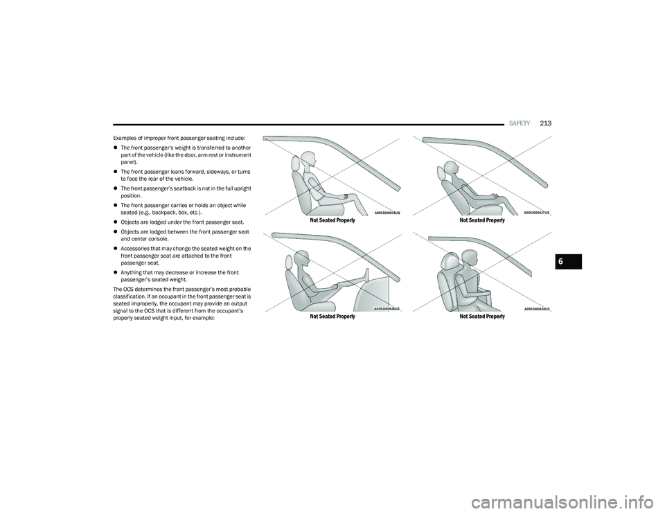
Examples of improper front passenger seating include:
The front passenger’s weight is transferred to another
part of the vehicle (like the door, arm rest or instrument
panel).
The front passenger leans forward, sideways, or turns
to face the rear of the vehicle.
The front passenger’s seatback is not in the full upright
position.
The front passenger carries or holds an object while
seated (e.g., backpack, box, etc.).
Objects are lodged under the front passenger seat.
Objects are lodged between the front passenger seat
and center console.
Accessories that may change the seated weight on the
front passenger seat are attached to the front
passenger seat.
Anything that may decrease or increase the front
passenger’s seated weight.
The OCS determines the front passenger’s most probable
classification. If an occupant in the front passenger seat is
seated improperly, the occupant may provide an output
signal to the OCS that is different from the occupant’s
properly seated weight input, for example:
Not Seated Properly
Not Seated Properly Not Seated Properly
Not Seated Properly
6
23_RUP_OM_EN_USC_t.book Page 213