2023 CHRYSLER PACIFICA light
[x] Cancel search: lightPage 279 of 328

SERVICING AND MAINTENANCE277
F10 ––Not Populated
F11 ––Not Populated
F12 –5 Amp TanBattery Sensor (IBS)
F13 –10 Amp Red ECM (S) *
F14 –10 Amp Red ECM
F15 40 Amp Green –CBC / Power Locks
F16 –20 Amp Yellow ECM
F17 30 Amp Pink –Starter
F18 40 Amp Green –CBC / EXT LIGHTS
F19 25 Amp Clear –2nd Row Folding Seats Solenoid LT *
F20 –10 Amp Red A/C Compressor Clutch
F21 25 Amp Clear –2nd Row Folding Seat Solenoid RT *
F22 ––Not Populated
F23 ––Not Populated
F24 –20 Amp Yellow RR Wiper
F25 –10 Amp RedHands-Free Dr Mod / Active Grille Shutter /
Pwr Mirror / VRM
F26 40 Amp Green –Front HVAC Blower Motor
F27 25 Amp Clear –RR Slide Door Module-RT *
F28 –10 Amp RedDiagnostic Port / USB+(IP) / Video USB
Port / Overhead DVD Player(Aftermarket)
F29 ––Not Populated
F30 –15 Amp BlueMedia HUB / Power Lumbar *
Cavity
Cartridge Fuse Blade FuseDescription
*If Equipped
8
23_RUP_OM_EN_USC_t.book Page 277
Page 280 of 328

278SERVICING AND MAINTENANCE
F31 ––Not Populated
F32 20 Amp Blue –ECM
F33 30 Amp Pink –Power Liftgate Module *
F34 25 Amp Clear –RR Door Module-LT *
F35 25 Amp Clear –Sunroof *
F36 ––Not Populated
F37 40 Amp Green –CBC / Exterior Lights
F38 60 Amp Yellow –Vacuum Cleaner *
F39 25 Amp Clear –Rear HVAC Blower Motor
F40 ––Not Populated
F41 ––Not Populated
F42 40 Amp Green –Folding Seat Module *
F43 –20 Amp Yellow Fuel Pump Motor
F44 30 Amp Pink –CBC / Interior Lights
F45 30 Amp Pink –Power Inverter *
F46 30 Amp Pink –Driver Door Module
F47 30 Amp Pink –Passenger Door Module
F48 ––Not Populated
F49 25 Amp Clear –RR Sliding Door Module-LT *
F50 25 Amp Clear –RR Door Module-RT *
F51 30 Amp Pink –Front Wiper
F52 30 Amp Pink –Brake Vacuum Pump
F53 ––Not Populated
Cavity
Cartridge Fuse Blade FuseDescription
*If Equipped
23_RUP_OM_EN_USC_t.book Page 278
Page 282 of 328

280SERVICING AND MAINTENANCE
F72 –10 Amp Red Heated Mirror *
F73 30 Amp Pink –Rear Defroster
F74 20 Amp Blue –Trailer Tow Backup Lights*
F75 –5 Amp TanOverhead Console / RR Center Stack
F76 –20 Amp YellowUconnect / Center Display / Telematics
F77 –10 Amp RedRR Entertainment / Media HUB / USB(S) /
Rain Sensor / Sunroof / RR View Mirror/ Overhead DVD Player / INT Monitoring Camera / Wireless Charging Pad
F78 –15 Amp BlueTCM (ZF) / E-Shifter / Cluster
F79 –10 Amp RedICS / HVAC / SCCM/ EPB SW
F80 ––Not Populated
F81 ––Not Populated
F82 ––Not Populated
F83 20 Amp Blue
–TT Park Lights *
30 Amp Pink –Headlamp Washer Pump *
F84 30 Amp Pink –Drive Train Control MOD *
F85 –20 Amp Yellow Cigar Lighter
F86 ––Not Populated
F87 ––Not Populated
F88 –20 Amp Yellow Front Heated Seats *
F89 –20 Amp Yellow Rear Heated Seats *
F90 ––Not Populated
Cavity
Cartridge Fuse Blade FuseDescription
*If Equipped
23_RUP_OM_EN_USC_t.book Page 280
Page 285 of 328

SERVICING AND MAINTENANCE283
2. Firmly grab the front side marker lamp socket and
rotate a quarter turn counterclockwise to remove it
from the lamp assembly.
Front Side Marker Lamp Bulb Removal
3. Remove bulb from the front side marker lamp socket and replace with a new bulb.
4. Install front side marker lamp socket in lamp assembly and rotate a quarter turn clockwise to lock
into place.
5. Position the inner wheel liner in place and install the three fasteners.
TIRES
TIRE SAFETY INFORMATION
Tire safety information will cover aspects of the following
information: Tire Markings, Tire Identification Numbers,
Tire Terminology and Definitions, Tire Pressures, and Tire
Loading.
Tire Markings
Tire Markings
NOTE:
P (Passenger) — Metric tire sizing is based on US design
standards. P-Metric tires have the letter “P” molded
into the sidewall preceding the size designation.
Example: P215/65R15 95H.
European — Metric tire sizing is based on European
design standards. Tires designed to this standard have
the tire size molded into the sidewall beginning with the
section width. The letter "P" is absent from this tire size
designation. Example: 215/65R15 96H.
LT (Light Truck) — Metric tire sizing is based on US
design standards. The size designation for LT-Metric
tires is the same as for P-Metric tires except for the
letters “LT” that are molded into the sidewall preceding
the size designation. Example: LT235/85R16.
Temporary spare tires are designed for temporary
emergency use only. Temporary high pressure compact
spare tires have the letter “T” or “S” molded into the
sidewall preceding the size designation. Example:
T145/80D18 103M.
High flotation tire sizing is based on US design stan -
dards and it begins with the tire diameter molded into
the sidewall. Example: 31x10.5 R15 LT.
1 — US DOT Safety Standards Code
(TIN)
2 — Size Designation
3 — Service Description
4 — Maximum Load
5 — Maximum Pressure
6 — Treadwear, Traction and
Temperature Grades
8
23_RUP_OM_EN_USC_t.book Page 283
Page 286 of 328

284SERVICING AND MAINTENANCE
TIRE SIZING CHART
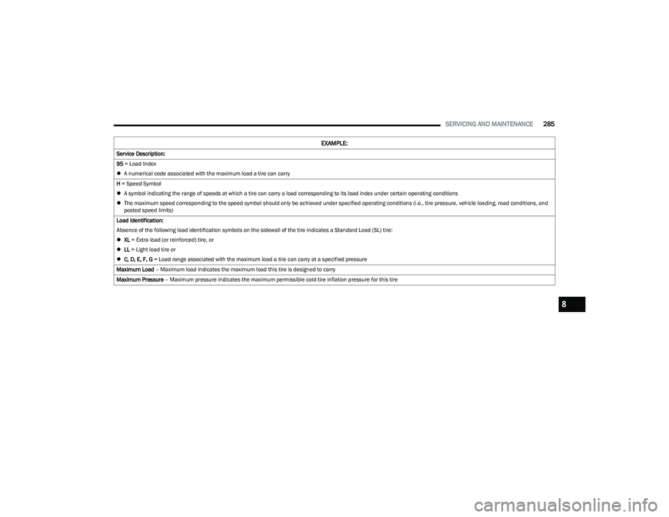
EXAMPLE:
Example Size Designation: P215/65R15XL 95H, 215/65R15 96H, LT235/85R16C, T145/80D18 103M, 31x10.5 R15 LT
P = Passenger car tire size based on US design standards, or
"....blank...." = Passenger car tire based on European design standards, or
LT = Light truck tire based on US design standards, or
T or S = Temporary spare tire or
31 = Overall diameter in inches (in)
215, 235, 145 = Section width in millimeters (mm)
65, 85, 80 = Aspect ratio in percent (%)
Ratio of section height to section width of tire, or
10.5 = Section width in inches (in)
R = Construction code
"R" means radial construction, or
"D" means diagonal or bias construction
15, 16, 18 = Rim diameter in inches (in)
23_RUP_OM_EN_USC_t.book Page 284
Page 287 of 328

SERVICING AND MAINTENANCE285
Service Description:
95 = Load Index
A numerical code associated with the maximum load a tire can carry
H = Speed Symbol
A symbol indicating the range of speeds at which a tire can carry a load corresponding to its load index under certain operating conditions
The maximum speed corresponding to the speed symbol should only be achieved under specified operating conditions (i.e., tire pressure, vehicle loading, road conditions, and
posted speed limits)
Load Identification:
Absence of the following load identification symbols on the sidewall of the tire indicates a Standard Load (SL) tire:
XL = Extra load (or reinforced) tire, or
LL = Light load tire or
C, D, E, F, G = Load range associated with the maximum load a tire can carry at a specified pressure
Maximum Load – Maximum load indicates the maximum load this tire is designed to carry
Maximum Pressure – Maximum pressure indicates the maximum permissible cold tire inflation pressure for this tire
EXAMPLE:
8
23_RUP_OM_EN_USC_t.book Page 285
Page 295 of 328

SERVICING AND MAINTENANCE293
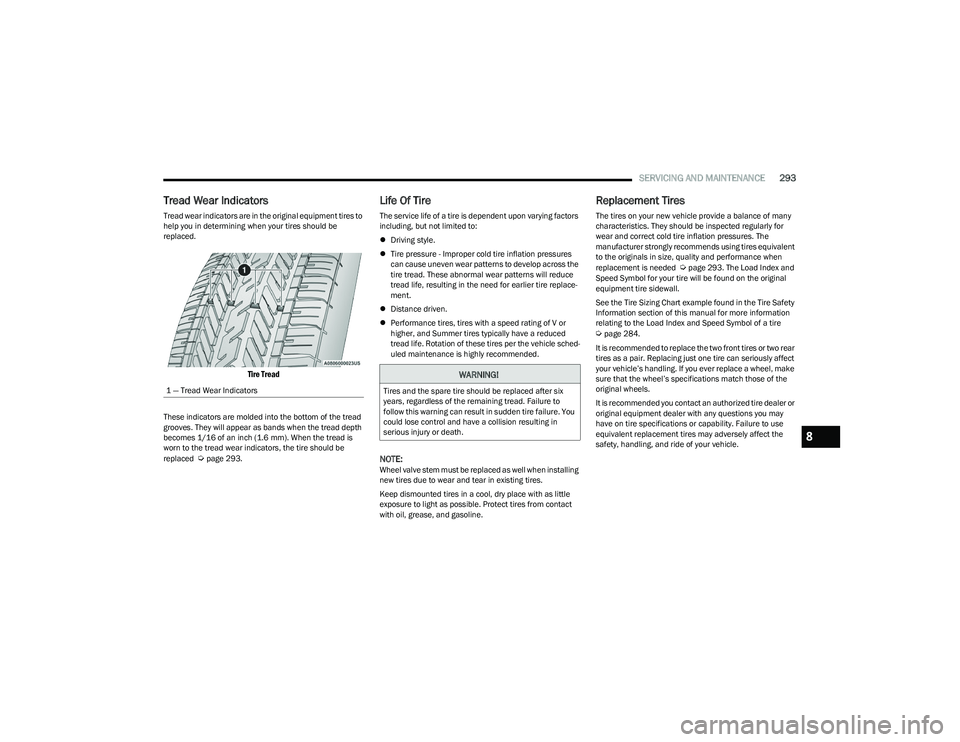
Tread Wear Indicators
Tread wear indicators are in the original equipment tires to
help you in determining when your tires should be
replaced.
Tire Tread
These indicators are molded into the bottom of the tread
grooves. They will appear as bands when the tread depth
becomes 1/16 of an inch (1.6 mm). When the tread is
worn to the tread wear indicators, the tire should be
replaced
Úpage 293.
Life Of Tire
The service life of a tire is dependent upon varying factors
including, but not limited to:
Driving style.
Tire pressure - Improper cold tire inflation pressures
can cause uneven wear patterns to develop across the
tire tread. These abnormal wear patterns will reduce
tread life, resulting in the need for earlier tire replace -
ment.
Distance driven.
Performance tires, tires with a speed rating of V or
higher, and Summer tires typically have a reduced
tread life. Rotation of these tires per the vehicle sched-
uled maintenance is highly recommended.
NOTE:Wheel valve stem must be replaced as well when installing
new tires due to wear and tear in existing tires.
Keep dismounted tires in a cool, dry place with as little
exposure to light as possible. Protect tires from contact
with oil, grease, and gasoline.
Replacement Tires
The tires on your new vehicle provide a balance of many
characteristics. They should be inspected regularly for
wear and correct cold tire inflation pressures. The
manufacturer strongly recommends using tires equivalent
to the originals in size, quality and performance when
replacement is needed
Úpage 293. The Load Index and
Speed Symbol for your tire will be found on the original
equipment tire sidewall.
See the Tire Sizing Chart example found in the Tire Safety
Information section of this manual for more information
relating to the Load Index and Speed Symbol of a tire
Úpage 284.
It is recommended to replace the two front tires or two rear
tires as a pair. Replacing just one tire can seriously affect
your vehicle’s handling. If you ever replace a wheel, make
sure that the wheel’s specifications match those of the
original wheels.
It is recommended you contact an authorized tire dealer or
original equipment dealer with any questions you may
have on tire specifications or capability. Failure to use
equivalent replacement tires may adversely affect the
safety, handling, and ride of your vehicle.
1 — Tread Wear Indicators
WARNING!
Tires and the spare tire should be replaced after six
years, regardless of the remaining tread. Failure to
follow this warning can result in sudden tire failure. You
could lose control and have a collision resulting in
serious injury or death.
8
23_RUP_OM_EN_USC_t.book Page 293
Page 302 of 328

300SERVICING AND MAINTENANCE
BODYWORK
PROTECTION FROM ATMOSPHERIC
A
GENTS
Vehicle body care requirements vary according to
geographic locations and usage. Chemicals that make
roads passable in snow and ice and those that are
sprayed on trees and road surfaces during other seasons
are highly corrosive to the metal in your vehicle. Outside
parking, which exposes your vehicle to airborne
contaminants, road surfaces on which the vehicle is
operated, extreme hot or cold weather and other extreme
conditions will have an adverse effect on paint, metal trim,
and underbody protection.
The following maintenance recommendations will enable
you to obtain maximum benefit from the corrosion
resistance built into your vehicle.
What Causes Corrosion?
Corrosion is the result of deterioration or removal of paint
and protective coatings from your vehicle.
The most common causes are:
Road salt, dirt and moisture accumulation.
Stone and gravel impact.
Insects, tree sap and tar.
Salt in the air near seacoast localities.
Atmospheric fallout/industrial pollutants.
BODY AND UNDERBODY MAINTENANCE
Cleaning Headlights
Your vehicle is equipped with plastic headlights and fog
lights that are lighter and less susceptible to stone
breakage than glass headlights.
Plastic is not as scratch resistant as glass and therefore
different lens cleaning procedures must be followed.
To minimize the possibility of scratching the lenses and
reducing light output, avoid wiping with a dry cloth. To
remove road dirt, wash with a mild soap solution followed
by rinsing.
Do not use abrasive cleaning components, solvents, steel
wool or other aggressive material to clean the lenses.
PRESERVING THE BODYWORK
Washing
Wash your vehicle regularly. Always wash your vehicle
in the shade using Mopar® Car Wash, or a mild car
wash soap, and rinse the panels completely with water.
If insects, tar, or other similar deposits have accumu -
lated on your vehicle, use Mopar® Super Kleen Bug
and Tar Remover to get rid of any deposits.
Use a high quality cleaner wax, such as Mopar®
Cleaner Wax to remove road film, stains and to protect
your paint finish. Use precautions to not scratch the
paint.
Avoid using abrasive compounds and power buffing
that may diminish the gloss or thin out the paint finish.
CAUTION!
Do not use abrasive or strong cleaning materials
such as steel wool or scouring powder that will
scratch metal and painted surfaces.
Use of power washers exceeding 1,200 psi
(8,274 kPa) can result in damage or removal of paint
and decals.
23_RUP_OM_EN_USC_t.book Page 300