2023 CHEVROLET CORVETTE pressure
[x] Cancel search: pressurePage 99 of 351

Chevrolet Corvette Owner Manual (GMNA-Localizing-U.S./Canada/Mexico-
16287457) - 2023 - CRC - 3/10/22
98 Instruments and Controls
English
Vehicle Alerts : Alerts can be dismissed in
the instrument cluster. All alerts are not
displayed in the HUD.
Care of the HUD
Clean the inside of the windshield to remove
any dirt or film that could reduce the
sharpness or clarity of the HUD image.
Clean the HUD lens with a soft cloth
sprayed with glass cleaner. Wipe the lens
gently, then dry it.
HUD Troubleshooting
Check that:
.Nothing is covering the HUD lens.
.HUD brightness setting is not too dim or
too bright.
.HUD is adjusted to the proper height.
.Polarized sunglasses are not worn.
.Windshield and HUD lens are clean. If the HUD image is not correct, contact
your dealer.
The windshield is part of the HUD system.
See
Windshield Replacement 0263.
Vehicle Messages
Messages displayed on the DIC indicate the
status of the vehicle or some action that
may be needed to correct a condition.
Multiple messages may appear one after
another.
The messages that do not require
immediate action can be acknowledged and
cleared by pressing
V. The messages that
require immediate action cannot be cleared
until that action is performed.
All messages should be taken seriously;
clearing the message does not correct the
problem.
If a SERVICE message appears, see your
dealer.
Follow the instructions given in the
messages. The system displays messages
regarding the following topics:
.Service Messages
.Fluid Levels
.Vehicle Security
.Brakes
.Steering
.Ride Control Systems
.Driver Assistance Systems
.Cruise Control
.Front Lift System
.Lighting and Bulb Replacement
.Wiper/Washer Systems
.Doors and Windows
.Seat Belts
.Airbag Systems
.Engine and Transmission
.Tire Pressure
.Battery
Engine Power Messages
REDUCED ACCELERATION DRIVE
WITH CARE
This message displays when the vehicle's
propulsion power is reduced. A reduction in
propulsion power can affect the vehicle's
ability to accelerate. If this message is on,
but there is no observed reduction in
performance, proceed to your destination.
Under certain conditions the performance
may be reduced the next time the vehicle is
Page 133 of 351
Chevrolet Corvette Owner Manual (GMNA-Localizing-U.S./Canada/Mexico-
16287457) - 2023 - CRC - 3/10/22
132 Infotainment System
Global Positioning System (GPS)
If equipped, the position of the vehicle is
determined by using satellite signals, various
vehicle signals, and map data.
At times, other interference such as the
satellite condition, road configuration,
condition of the vehicle, and/or other
circumstances can affect the navigation
system's ability to determine the accurate
position of the vehicle.
The GPS shows the current position of the
vehicle using signals sent by GPS satellites.
When the vehicle is not receiving signals
from the satellites, a symbol appears in the
status bar.
This system might not be available or
interference can occur if any of the
following are true:
.Signals are obstructed by tall buildings,
trees, large trucks, or a tunnel.
.Satellites are being repaired or improved.
For more information if the GPS is not
functioning properly, see Problems with
Route Guidance 0132 and
If the System Needs Service 0133.
Vehicle Positioning
At times, the position of the vehicle on the
map could be inaccurate due to one or more
of the following reasons:
.The road system has changed.
.The vehicle is driving on slippery road
surfaces such as sand, gravel, or snow.
.The vehicle is traveling on winding roads
or long, straight roads.
.The vehicle is approaching a tall building
or a large vehicle.
.The surface streets run parallel to a
freeway.
.The vehicle has been transferred by a
vehicle carrier or a ferry.
.The current position calibration is set
incorrectly.
.The vehicle is traveling at high speed.
.The vehicle changes directions more than
once, or the vehicle is turning on a turn
table in a parking lot.
.The vehicle is entering and/or exiting a
parking lot, garage, or a lot with a roof.
.The GPS signal is not received.
.A roof carrier is installed on the vehicle.
.Tire chains are installed on the vehicle.
.The tires are replaced or worn.
.The tire pressure for the tires is incorrect.
.This is the first navigation use after the
map data is updated.
.The 12-volt battery has been disconnected
for several days.
.The vehicle is driving in heavy traffic
where driving is at low speeds, and the
vehicle is stopped and started repeatedly.
Problems with Route Guidance
Inappropriate route guidance can occur
under one or more of the following
conditions:
.The turn was not made on the road
indicated.
.Route guidance might not be available
when using automatic rerouting for the
next right or left turn.
.The route might not be changed when
using automatic rerouting.
.There is no route guidance when turning
at an intersection.
.Plural names of places might be
announced occasionally.
.It could take a long time to operate
automatic rerouting during high-speed
driving.
Page 182 of 351
Chevrolet Corvette Owner Manual (GMNA-Localizing-U.S./Canada/Mexico-
16287457) - 2023 - CRC - 3/10/22
Driving and Operating 181
Shock Spring Seat Adjustment
The front shocks, on vehicles without
hydraulic front lift and rear shocks, have
threaded spring seats that allow adjustment
of the preload on the coil springs. The
vehicle corner weights can be adjusted for
track use. If the vehicle trim height is
modified, it should be returned to normal
trim height before street use.
The spring seat can be adjusted
approximately 20 mm (0.8 in) up or down
from the nominal position. Each complete
turn of the spring seat will change the
vehicle height approximately 1.5 mm
(0.06 in). When adjusting the seat to the
upper limit, lift the dust boot and ensure
the seat does not thread off the center
support tube (stop adjustment when threads
no longer visible). When adjusting the seat
to the lower limit, leave approximately
10 mm (0.4 in) of thread visible for the
lower lock nut to have full thread
engagement.
The following procedure can be complex and
should only be performed by trained
personnel. See your dealer.To adjust the lower spring seat:
1. Raise the vehicle so the tires are completely off the ground.
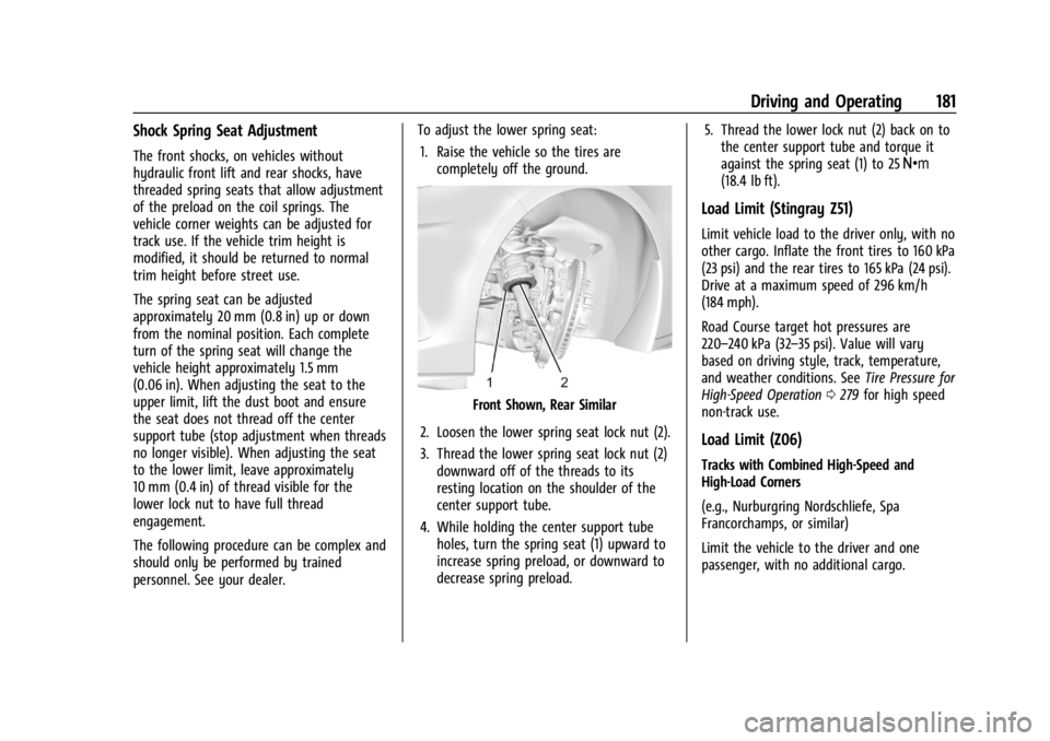
Front Shown, Rear Similar
2. Loosen the lower spring seat lock nut (2).
3. Thread the lower spring seat lock nut (2) downward off of the threads to its
resting location on the shoulder of the
center support tube.
4. While holding the center support tube holes, turn the spring seat (1) upward to
increase spring preload, or downward to
decrease spring preload. 5. Thread the lower lock nut (2) back on to
the center support tube and torque it
against the spring seat (1) to 25 Y
(18.4 lb ft).
Load Limit (Stingray Z51)
Limit vehicle load to the driver only, with no
other cargo. Inflate the front tires to 160 kPa
(23 psi) and the rear tires to 165 kPa (24 psi).
Drive at a maximum speed of 296 km/h
(184 mph).
Road Course target hot pressures are
220–240 kPa (32–35 psi). Value will vary
based on driving style, track, temperature,
and weather conditions. See Tire Pressure for
High-Speed Operation 0279 for high speed
non-track use.
Load Limit (Z06)
Tracks with Combined High-Speed and
High-Load Corners
(e.g., Nurburgring Nordschliefe, Spa
Francorchamps, or similar)
Limit the vehicle to the driver and one
passenger, with no additional cargo.
Page 183 of 351
Chevrolet Corvette Owner Manual (GMNA-Localizing-U.S./Canada/Mexico-
16287457) - 2023 - CRC - 3/10/22
182 Driving and Operating
Cold Tire Pressure Requirement: Inflate tires
to no less than 210 kPa (30 psi) front and
rear, cold.
Hot Tire Pressure Target Range:
220–240 kPa (32-35 psi).
Road/Street Courses
(e.g., Virginia International Raceway, Road
Atlanta, or similar)
Limit the vehicle to the driver and one
passenger, with no additional cargo.
Cold Tire Pressure Requirement: Inflate tires
to no less than 165 kPa (24 psi) front and
rear, cold.
Hot Tire Pressure Target Range:
220 –240 kPa (32-35 psi).
See Tire Pressure for High-Speed Operation
0 279 for high speed non track use.
Wheel Alignment
Caution
Using these wheel alignment settings
may cause excessive tire wear. Only use
these wheel alignment settings for racing
(Continued)
Caution (Continued)
or competitive driving. Excessive tire wear
is not covered under the vehicle
warranty.
Caution
Do not use power tools when removing
or installing the fasteners. Damage to the
threads may occur. Use hand tools only,
and do not overtighten. Hand start the
fasteners to ensure that the threads do
not bind or cross thread.
The racing and competitive driving wheel
alignment settings should be set as
described here.
Stingray Z51
To achieve the track alignment specified
settings: 1. The upper control arm to body washers on all four corners must be moved from
between the body and the control arm
and relocated between the head of the
bolt and the control arm. 2. Adjust the lower control arm cam bolt
position to achieve the following
specifications:
Front (per corner)
.Caster: +8.0 degrees
.Camber: -3.0 degrees
.Toe (total): 0.1 degrees toe in
Rear (per corner)
.Caster: 0 degrees
.Camber: -2.5 degrees
.Toe (total): 0.1 degrees toe in
.Thrust Angle: 0 degrees
After track use, reinstall washers between
the body and the control arms. Reset to
factory alignment settings. See your dealer.
Z06 1. The upper control arm washers do not need to be removed for Z06.
2. Adjust the lower control arm cam bolt position to achieve the following
specifications:
Front (per corner)
.Caster: +8.0 degrees
.Camber: -2.0 degrees
.Toe (total): 0.1 degrees toe in
Page 188 of 351
Chevrolet Corvette Owner Manual (GMNA-Localizing-U.S./Canada/Mexico-
16287457) - 2023 - CRC - 3/10/22
Driving and Operating 187
pressures (4). For more information on
tires and inflation seeTires0271 and
Tire Pressure 0278.
There is also important loading
information on the vehicle Certification
label. It may show the Gross Vehicle
Weight Rating (GVWR) and the Gross
Axle Weight Rating (GAWR) for the
front and rear axle. See “Certification
Label” later in this section.
Steps for Determining Correct Load Limit–
1.
Locate the statement "The combined
weight of occupants and cargo
should never exceed XXX kg or
XXX lbs." on your vehicle’s placard.
2.Determine the combined weight of
the driver and passengers that will
be riding in your vehicle.
3.Subtract the combined weight of the
driver and passengers from XXX kg
or XXX lbs.
4.The resulting figure equals the
available amount of cargo and
luggage load capacity. For example,
if the "XXX" amount equals 1400 lbs.
and there will be five 150 lb
passengers in your vehicle, the
amount of available cargo and
luggage load capacity is 650 lbs.
(1400-750 (5 x 150) = 650 lbs.)
5.Determine the combined weight of
luggage and cargo being loaded on
the vehicle. That weight may not
safely exceed the available cargo and
luggage load capacity calculated in
Step 4.
6.If your vehicle will be towing a
trailer, load from your trailer will be
transferred to your vehicle. Consult
this manual to determine how this
reduces the available cargo and
luggage load capacity of your
vehicle.”
This vehicle is neither designed nor
intended to tow a trailer.
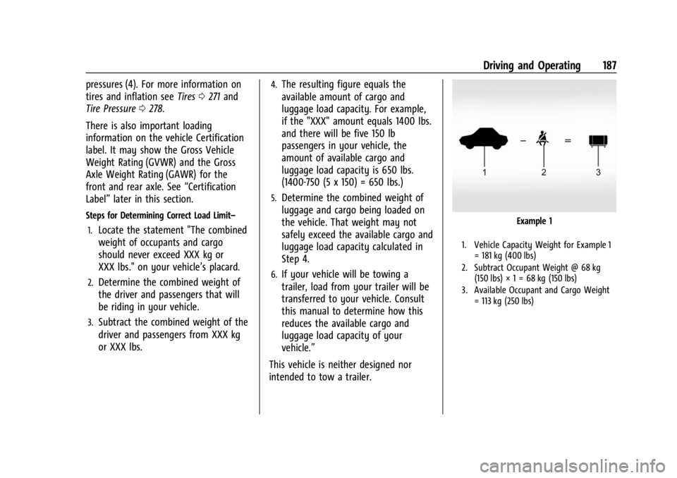
Example 1
1. Vehicle Capacity Weight for Example 1 = 181 kg (400 lbs)
2. Subtract Occupant Weight @ 68 kg (150 lbs) × 1 = 68 kg (150 lbs)
3. Available Occupant and Cargo Weight = 113 kg (250 lbs)
Page 191 of 351
Chevrolet Corvette Owner Manual (GMNA-Localizing-U.S./Canada/Mexico-
16287457) - 2023 - CRC - 3/10/22
190 Driving and Operating
{Warning
Exposed edges of parts containing carbon
fiber and other composite materials can
be sharp. Contact with these parts could
result in injury. Use caution to avoid
contacting these parts, including when
washing the vehicle. If the parts are
damaged, replace the parts promptly
with replacements from your dealer.
{Warning
Rocker extensions may break under
pressure, resulting in property damage or
injury. Do not stand on the rocker
extension or use it as a step.
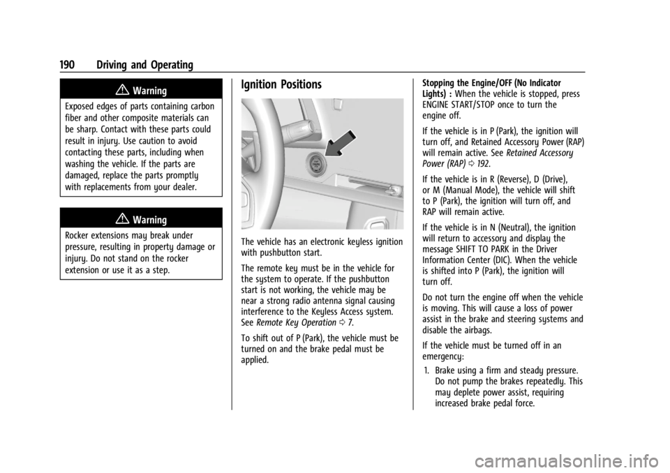
Ignition Positions
The vehicle has an electronic keyless ignition
with pushbutton start.
The remote key must be in the vehicle for
the system to operate. If the pushbutton
start is not working, the vehicle may be
near a strong radio antenna signal causing
interference to the Keyless Access system.
SeeRemote Key Operation 07.
To shift out of P (Park), the vehicle must be
turned on and the brake pedal must be
applied. Stopping the Engine/OFF (No Indicator
Lights) :
When the vehicle is stopped, press
ENGINE START/STOP once to turn the
engine off.
If the vehicle is in P (Park), the ignition will
turn off, and Retained Accessory Power (RAP)
will remain active. See Retained Accessory
Power (RAP) 0192.
If the vehicle is in R (Reverse), D (Drive),
or M (Manual Mode), the vehicle will shift
to P (Park), the ignition will turn off, and
RAP will remain active.
If the vehicle is in N (Neutral), the ignition
will return to accessory and display the
message SHIFT TO PARK in the Driver
Information Center (DIC). When the vehicle
is shifted into P (Park), the ignition will
turn off.
Do not turn the engine off when the vehicle
is moving. This will cause a loss of power
assist in the brake and steering systems and
disable the airbags.
If the vehicle must be turned off in an
emergency: 1. Brake using a firm and steady pressure. Do not pump the brakes repeatedly. This
may deplete power assist, requiring
increased brake pedal force.
Page 207 of 351

Chevrolet Corvette Owner Manual (GMNA-Localizing-U.S./Canada/Mexico-
16287457) - 2023 - CRC - 3/10/22
206 Driving and Operating
accelerator pedal apply. The brakes release
when the accelerator pedal is applied. If the
accelerator pedal is not applied within a few
minutes, the Electric Parking Brake will
apply. The brakes may also release under
other conditions. Do not rely on HSA to hold
the vehicle.
HSA is available when the vehicle is facing
uphill in a forward gear, or when facing
downhill in R (Reverse). The vehicle must
come to a complete stop on a grade for HSA
to activate.
Ride Control Systems
Traction Control/Electronic
Stability Control
The vehicle has a Traction Control
System (TCS) and a StabiliTrak/Electronic
Stability Control (ESC) system. These
systems help limit wheel spin and assist the
driver in maintaining control, especially on
slippery road conditions.
TCS activates if it senses that the rear
wheels are spinning too much or are
beginning to lose traction. When this
happens, TCS applies the brakes to thespinning wheel and reduces engine power
(by closing the throttle and managing
engine spark) to limit wheel spin.
StabiliTrak/ESC activates when the vehicle
senses a difference between the intended
path and the direction the vehicle is actually
traveling. StabiliTrak/ESC selectively applies
braking pressure to any one of the vehicle
wheel brakes to assist the driver in keeping
the vehicle on the intended path.
If cruise control is being used when TCS
begins to limit wheel spin, the cruise control
will automatically disengage. Cruise control
may be reengaged when road conditions
allow. See
Cruise Control 0219.
If the driver disables TCS, cruise control will
disengage. Cruise control will also be
disabled if Performance Traction
Management (PTM) is selected, or if
StabiliTrak is turned off.
Both systems come on automatically when
the vehicle is started and begins to move.
The systems may be heard or felt while
they are operating or while performing
diagnostic checks. This is normal and does
not mean there is a problem with the
vehicle. It is recommended to leave both systems on
for normal driving conditions, but it may be
necessary to turn TCS off if the vehicle gets
stuck in sand, mud, ice, or snow. See
If the
Vehicle Is Stuck 0185 and “Turning the
Systems Off and On” later in this section.
The indicator light for both systems is in the
instrument cluster. This light will:
.Flash when TCS is limiting wheel spin
.Flash when StabiliTrak/ESC is activated
.Flash when ABS is active
.Turn on and stay on when either system
is not working
If either system fails to turn on or to
activate, a message displays in the Driver
Information Center (DIC), and
=comes on
and stays on to indicate that the system is
inactive and is not assisting the driver in
maintaining control. The vehicle is safe to
drive, but driving should be adjusted
accordingly.
Page 208 of 351
Chevrolet Corvette Owner Manual (GMNA-Localizing-U.S./Canada/Mexico-
16287457) - 2023 - CRC - 3/10/22
Driving and Operating 207
If=comes on and stays on:
1. Stop the vehicle.
2. Turn the engine off and wait 15 seconds.
3. Start the engine.
Drive the vehicle. If
=comes on and
stays on, the vehicle may need more time
to diagnose the problem. If the condition
persists, see your dealer.
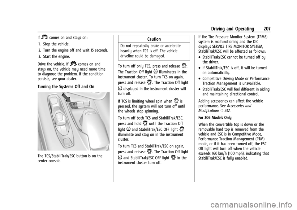
Turning the Systems Off and On
The TCS/StabiliTrak/ESC button is on the
center console.
Caution
Do not repeatedly brake or accelerate
heavily when TCS is off. The vehicle
driveline could be damaged.
To turn off only TCS, press and release
@.
The Traction Off light
iilluminates in the
instrument cluster. To turn TCS on again,
press and release
@. The Traction Off light
idisplayed in the instrument cluster will
turn off.
If TCS is limiting wheel spin when
@is
pressed, the system will not turn off until
the wheels stop spinning.
To turn off both TCS and StabiliTrak/ESC,
press and hold
@until the Traction Off
light
iand StabiliTrak/ESC OFF light@
illuminate and stay on in the instrument
cluster.
To turn TCS and StabiliTrak/ESC on again,
press and release
@. The Traction Off light
iand StabiliTrak/ESC OFF light@in the
instrument cluster turn off. If the Tire Pressure Monitor System (TPMS)
system is malfunctioning and the DIC
displays SERVICE TIRE MONITOR SYSTEM,
StabiliTrak/ESC will be affected as follows:
.StabiliTrak/ESC cannot be turned off by
the driver.
.If StabiliTrak/ESC is off, it will be turned
on automatically.
.Competitive Driving Mode or Performance
Traction Management is unavailable.
.StabiliTrak/ESC will feel different in aiding
and maintaining directional control.
Adding accessories can affect the vehicle
performance. See Accessories and
Modifications 0232.
For Z06 Models Only
When the convertible top is down or the
removable hard top is removed from the
vehicle and ESC is in Competitive Mode,
Performance Traction Management (PTM)
mode, or if it has been turned off, the ESC
Off light will turn off when the vehicle
exceeds 160 km/h (100 mph), indicating that
StabiliTrak/ESC is fully enabled.