2023 CHEVROLET COLORADO manual mode
[x] Cancel search: manual modePage 224 of 362

Chevrolet Colorado Owner Manual (GMNA-Localizing-U.S./Canada/Mexico-
15274222) - 2022 - CRC - 11/2/21
Driving and Operating 223
Disconnect the wiring to the trailer before
backing the trailer into the water to prevent
damage to the electrical circuits on the
trailer. Reconnect the wiring to the trailer
after removing the trailer from the water.
If the trailer has electric brakes that can
function when the trailer is submerged, it
might help to leave the electrical trailer
connector attached to maintain trailer brake
functionality while on the boat ramp.
To back the trailer into the water:1. If equipped, place the vehicle in four-wheel-drive high.
2. Slowly back down the boat ramp until the boat is floating, but no further than
necessary.
3. Press and hold the brake pedal, but do not shift into P (Park) yet.
4. Have someone place chocks under the front wheels of the vehicle.
5. Gradually release the brake pedal to allow the chocks to absorb the load of
the trailer.
6. Reapply the brake pedal. Then apply the parking brake and shift into P (Park).
7. Release the brake pedal. Pulling the Trailer from the Water
To pull the trailer of the water:
1. Press and hold the brake pedals.
2. Start the engine and shift into gear.
3. Release the parking brake.
4. Let up on the brake pedal.
5. Drive slowly until the tires are clear of the chocks.
6. Stop and have someone pick up and store the chocks.
7. Slowly pull the trailer from the water.
8. Once the vehicle and trailer have been driven from the sloped part of the boat
ramp, the vehicle can be shifted from
four-wheel-drive high. Shift into the drive
mode that is appropriate for the road
conditions.
Caution
If the vehicle tires begin to spin and the
vehicle begins to slide toward the water,
remove your foot from the accelerator
pedal and apply the brake pedal. Seek
help to have the vehicle towed up
the ramp.
Maintenance when Trailer Towing
The vehicle needs service more often when
used to tow trailers. See Maintenance
Schedule 0314. It is especially important to
check the automatic transmission fluid,
engine oil, axle lubricant, belts, cooling
system, and brake system before and during
each trip.
Check periodically to see that all nuts and
bolts on the trailer hitch are tight.
Engine Cooling When Trailer Towing
The cooling system may temporarily
overheat during severe operating conditions.
See Engine Overheating 0249.
Trailer Towing
If equipped with a diesel engine, see the
Duramax diesel supplement.
Caution
Towing a trailer improperly can damage
the vehicle and result in costly repairs
not covered by the vehicle warranty. To
tow a trailer correctly, follow the
directions in this section and see your
dealer for important information about
towing a trailer with the vehicle.
Page 226 of 362
Chevrolet Colorado Owner Manual (GMNA-Localizing-U.S./Canada/Mexico-
15274222) - 2022 - CRC - 11/2/21
Driving and Operating 225
2. Add the weight of the trailer loaded withcargo and ready for the trip.
3. Add the weight of all passengers.
4. Add the weight of all cargo in the vehicle.
5. Add the weight of hitch hardware such as a draw bar, ball, load equalizer bars,
or sway bars.
6. Add the weight of any accessories or aftermarket equipment added to the
vehicle.
The resulting weight cannot exceed the
GCWR for the vehicle.
The gross combined weight can also be
confirmed by weighing the truck and trailer
on a public scale. The truck and trailer
should be loaded for the trip with
passengers and cargo.
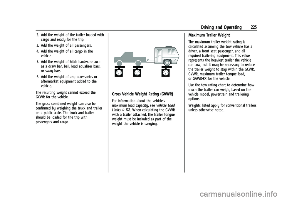
Gross Vehicle Weight Rating (GVWR)
For information about the vehicle's
maximum load capacity, see Vehicle Load
Limits 0178. When calculating the GVWR
with a trailer attached, the trailer tongue
weight must be included as part of the
weight the vehicle is carrying.
Maximum Trailer Weight
The maximum trailer weight rating is
calculated assuming the tow vehicle has a
driver, a front seat passenger, and all
required trailering equipment. This value
represents the heaviest trailer the vehicle
can tow, but it may be necessary to reduce
the trailer weight to stay within the GCWR,
GVWR, maximum trailer tongue load,
or GAWR-RR for the vehicle.
Use the tow rating chart to determine how
much the trailer can weigh, based on the
vehicle model, powertrain and trailering
options.
Weights listed apply for conventional trailers
unless otherwise noted.
Page 230 of 362

Chevrolet Colorado Owner Manual (GMNA-Localizing-U.S./Canada/Mexico-
15274222) - 2022 - CRC - 11/2/21
Driving and Operating 229
Standards Association (CSA) requirement
CAN3-D313, or its equivalent, is
recommended.
State or local regulations may require
trailers to have their own braking system if
the loaded weight of the trailer exceeds
certain minimums that can vary from state
to state. Read and follow the instructions for
the trailer brakes so they are installed,
adjusted, and maintained properly. Never
attempt to tap into your vehicle's hydraulic
brake system. If you do, both the vehicle
anti-lock brakes and the trailer brakes may
not function, which could result in a crash.
Trailer Wiring Harness
For vehicles not equipped with heavy-duty
trailering, a harness is secured underneath
the left side of the vehicle, next to the spare
tire. The harness requires the installation of
a trailer connector, which is available
through your dealer. The seven-wire harness
contains the following trailer circuits:
.Yellow: Left stop/turn signal
.Green: Right stop/turn signal
.Brown: Taillamps/parking lamps
.Black: Ground
.Gray: Back-up lamps
.Orange: Battery feed
.Blue: Trailer brake
To help charge a remote (non-vehicle)
battery, press the Tow/Haul Mode button
on the center stack. If the trailer is too light
for Tow/Haul Mode, turn on the headlamps
to help charge the battery.
Trailer Brake Control Wiring Harness
A four-wire harness, without connector, is
secured behind the left side kick panel. The
harness contains the following circuits:
.Red/Green: Battery feed
.Black: Ground
.White/Blue: Brake signal to controller
.Blue: Trailer Brake power to trailer
connector To remove the left side kick panel, start at
the front of the panel pulling toward the
rear of the vehicle and lift upward to
disengage the integral clips.
Turn Signals When Towing a Trailer
When properly connected, the trailer turn
signals will illuminate to indicate the vehicle
is turning, changing lanes, or stopping.
When towing a trailer, the arrows on the
instrument cluster will illuminate even if the
trailer is not properly connected or the bulbs
are burned out.
Tow/Haul Mode
For instructions on how to enter Tow/Haul
Mode, see
Tow/Haul Mode 0194.
Tow/Haul assists when pulling a heavy
trailer or a large or heavy load.
Tow/Haul Mode is designed to be most
effective when the vehicle and trailer
combined weight is at least 75% of the
vehicle's Gross Combined Weight Rating
(GCWR). See “Weight of the Trailer” under
Trailer Towing 0223.
Tow/Haul Mode is most useful when towing
a heavy trailer or carrying a large or
heavy load:
.through rolling terrain.
Page 231 of 362

Chevrolet Colorado Owner Manual (GMNA-Localizing-U.S./Canada/Mexico-
15274222) - 2022 - CRC - 11/2/21
230 Driving and Operating
.in stop-and-go traffic.
.in busy parking lots.
Operating the vehicle in Tow/Haul Mode
when lightly loaded or not towing will not
cause damage; however, it is not
recommended and may result in unpleasant
engine and transmission driving
characteristics and reduced fuel economy.
Integrated Trailer Brake Control System
The vehicle may have an Integrated Trailer
Brake Control (ITBC) system for use with
electric trailer brakes or most electric over
hydraulic trailer brake systems. These
instructions apply to both types of electric
trailer brakes.
This symbol is on the Trailer Brake Control
Panel on vehicles with an ITBC system. The
power output to the trailer brakes is
proportional to the amount of vehicle
braking. This available power output to the
trailer brakes can be adjusted to a wide
range of trailering situations. The ITBC system is integrated with the
vehicle’s brake, antilock brake, and
StabiliTrak/Electronic Stability Control (ESC)
systems. In trailering conditions that cause
the vehicle’s antilock brake or StabiliTrak/
ESC systems to activate, power sent to the
trailer's brakes will be automatically
adjusted to minimize trailer wheel lock-up.
This does not imply that the trailer has
StabiliTrak/ESC.
If the vehicle’s brake, anti-lock brake,
or StabiliTrak/ESC systems are not
functioning properly, the ITBC system may
not function fully or at all. Make sure all of
these systems are fully operational to allow
the ITBC system to function properly.
The ITBC system is powered through the
vehicle's electrical system. Turning the
ignition off will also turn off the ITBC
system. The ITBC system is fully functional
only when the ignition is in ON/RUN.{Warning
Connecting a trailer that has an air brake
system may result in reduced or
complete loss of trailer braking, including
increased stopping distance or trailer
instability which could result in serious
(Continued)
Warning (Continued)
injury, death, or property damage. Only
use the ITBC system with electric or
electric over hydraulic trailer brake
systems.
Trailer Brake Control Panel
1. Manual Trailer Brake Apply Lever
2. Integrated Trailer Brake Control (ITBC)
3. Trailer Gain Adjustment Buttons
The ITBC control panel is on the instrument
panel to the left of the steering column. The
control panel allows adjustment to the
amount of output, referred to as Trailer
Gain, available to the trailer brakes and
Page 235 of 362

Chevrolet Colorado Owner Manual (GMNA-Localizing-U.S./Canada/Mexico-
15274222) - 2022 - CRC - 11/2/21
234 Driving and Operating
Warning (Continued)
.Ask the device or trailer manufacturer
if the device has been thoroughly
tested for compatibility with the
make, model, and year of your vehicle
and any optional equipment installed
on your vehicle.
.Before driving, check the trailer brakes
are working properly, if equipped.
Drive the vehicle with the trailer
attached on a level road surface that
is free of traffic at about 32-40 km/h
(20-25 mph) and fully apply the
manual trailer brake apply lever. Also,
check the trailer brake lamps and
other lamps are functioning correctly.
.If the trailer brakes are not operating
properly at any time, or if a DIC
message indicates problems with the
trailer connections or trailer brakes,
carefully pull the vehicle over to the
side of the road when traffic
conditions allow.
Trailer Tires
Special Trailer (ST) tires differ from vehicle
tires. Trailer tires are designed with stiff
sidewalls to help prevent sway and tosupport heavy loads. These features can
make it difficult to determine if the trailer
tire pressures are low only based on a visual
inspection.
Always check all trailer tire pressures before
each trip when the tires are cool. Low trailer
tire pressure is a leading cause of trailer tire
blowouts.
Trailer tires deteriorate over time. The trailer
tire sidewall will show the week and year
the tire was manufactured. Many trailer tire
manufacturers recommend replacing tires
more than six years old.
Overloading is another leading cause of
trailer tire blowouts. Never load your trailer
with more weight than the tires are
designed to support. The load rating is
located on the trailer tire sidewall.
Always know the maximum speed rating for
the trailer tires before driving. This may be
significantly lower than the vehicle tire
speed rating. The speed rating may be on
the trailer tire sidewall. If the speed rating is
not shown, the default trailer tire speed
rating is 105 km/h (65 mph).
Conversions and Add-Ons
Add-On Electrical Equipment
{Warning
The Data Link Connector (DLC) is used for
vehicle service and Emission Inspection/
Maintenance testing. See
Malfunction
Indicator Lamp (Check Engine Light) 087.
A device connected to the DLC —such as
an aftermarket fleet or driver-behavior
tracking device —may interfere with
vehicle systems. This could affect vehicle
operation and cause a crash. Such devices
may also access information stored in the
vehicle’s systems.
Caution
Some electrical equipment can damage
the vehicle or cause components to not
work and would not be covered by the
vehicle warranty. Always check with your
dealer before adding electrical equipment.
Add-on equipment can drain the vehicle's
12-volt battery, even if the vehicle is not
operating.
Page 275 of 362

Chevrolet Colorado Owner Manual (GMNA-Localizing-U.S./Canada/Mexico-
15274222) - 2022 - CRC - 11/2/21
274 Vehicle Care
Bias Ply Tire:A pneumatic tire in which
the plies are laid at alternate angles
less than 90 degrees to the centerline
of the tread.
Cold Tire Pressure
:The amount of air
pressure in a tire, measured in kPa
(kilopascal) or psi (pounds per square
inch) before a tire has built up heat
from driving. See Tire Pressure0275.
Curb Weight
:The weight of a motor
vehicle with standard and optional
equipment including the maximum
capacity of fuel, oil, and coolant, but
without passengers and cargo.
DOT Markings
:A code molded into the
sidewall of a tire signifying that the tire
is in compliance with the U.S.
Department of Transportation (DOT)
Motor Vehicle Safety Standards. The
DOT code includes the Tire Identification
Number (TIN), an alphanumeric
designator which can also identify the
tire manufacturer, production plant,
brand, and date of production.
GVWR
:Gross Vehicle Weight Rating.
See Vehicle Load Limits 0178. GAWR FRT
:Gross Axle Weight Rating
for the front axle. See Vehicle Load
Limits 0178.
GAWR RR
:Gross Axle Weight Rating
for the rear axle. See Vehicle Load
Limits 0178.
Intended Outboard Sidewall
:The side
of an asymmetrical tire that must
always face outward when mounted on
a vehicle.
Kilopascal (kPa)
:The metric unit for air
pressure.
Light Truck (LT-Metric) Tire
:A tire used
on light duty trucks and some
multipurpose passenger vehicles.
Load Index
:An assigned number
ranging from 1 to 279 that corresponds
to the load carrying capacity of a tire.
Maximum Inflation Pressure
:The
maximum air pressure to which a cold
tire can be inflated. The maximum air
pressure is molded onto the sidewall.
Maximum Load Rating
:The load rating
for a tire at the maximum permissible
inflation pressure for that tire. Maximum Loaded Vehicle Weight
:The
sum of curb weight, accessory weight,
vehicle capacity weight, and production
options weight.
Normal Occupant Weight
:The number
of occupants a vehicle is designed to
seat multiplied by 68 kg (150 lb). See
Vehicle Load Limits 0178.
Occupant Distribution
:Designated
seating positions.
Outward Facing Sidewall
:The side of
an asymmetrical tire that has a
particular side that faces outward when
mounted on a vehicle. The side of the
tire that contains a whitewall, bears
white lettering, or bears manufacturer,
brand, and/or model name molding
that is higher or deeper than the same
moldings on the other sidewall of
the tire.
Passenger (P-Metric) Tire
:A tire used
on passenger cars and some light duty
trucks and multipurpose vehicles.
Page 289 of 362

Chevrolet Colorado Owner Manual (GMNA-Localizing-U.S./Canada/Mexico-
15274222) - 2022 - CRC - 11/2/21
288 Vehicle Care
Extended Cab
1. Jack Cover
2. Tool Bag Cover
To access and remove the jack and tools:1. Pull the bottom of the jack cover (1) forward to remove it.
2. Pull the lower access pocket forward and then upward to remove the tool bag
cover (2).
3. Turn the knob on the jack (1)counterclockwise to lower the jack head
to release the jack from its holder.
4. Turn the wing nut (2) counterclockwise to remove the jack and wheel blocks.
5. Turn the wing nut (3) counterclockwise to remove the tool bag.
Use the jack handle extensions and the
wheel wrench to remove the
underbody-mounted spare tire.1. Spare Tire (Valve Stem Pointed Down for All Except ZR2 Models. Valve Stem
Pointed Up for ZR2 Models.)
2. Tire/Wheel Retainer
3. Hoist Cable
4. Hoist Assembly
5. Hoist Shaft
6. Jack Handle Extensions
7. Wheel Wrench
8. Spare Tire Lock (If Equipped)
9. Hoist Shaft Access Hole
10. Hoist End of Extension Tool
1. Open the spare tire lock cover on the bumper.
Page 291 of 362

Chevrolet Colorado Owner Manual (GMNA-Localizing-U.S./Canada/Mexico-
15274222) - 2022 - CRC - 11/2/21
290 Vehicle Care
1. Jack
2. Wheel Blocks
3. Jack Handle
4. Jack Handle Extensions
5. Wheel Wrench
1. Do a safety check before proceeding. SeeIf a Tire Goes Flat 0286.
2. If the wheel has a center cap that covers
the lug nuts, place the chisel end of the
wheel wrench in each of the slots in the
cap, and gently pry it out.
3. Use the wheel wrench and turn itcounterclockwise to loosen the wheel
nuts. Do not remove the wheel nuts yet.
Front Position —ZR2 Models
4. For ZR2 Models, position the jack under the control arm, as shown.
Front Position —All Except ZR2 Models