2023 CHEVROLET BOLT EV battery
[x] Cancel search: batteryPage 199 of 308

Chevrolet BOLT EV Owner Manual (GMNA-Localizing-U.S./Canada-
16404388) - 2023 - CRC - 3/7/22
198 Driving and Operating
There are several infotainment screens that
will display depending on the current
charging status. SeeProgrammable Charging
0 90.
Charging Override
A CHARGING OVERRIDE/INTERRUPTION
OCCURRED message may display to indicate
that a charging override or interruption has
occurred due to one or more of the
following events:
.Override of the charge settings by the
owner.
.Unintended interruption of AC power at
the vehicle's charge port.
.Interruption of charging by the utility
company.
AC Charging
A loss of AC power alert may sound for a
short time if AC power is lost for over
one minute. This sound alert can be turned
off. See Programmable Charging 090.
AC Charge Cord Vehicle Plug
To Start AC Charging 1. Put the vehicle in P (Park).
2. Push the rearward edge of the charge port door and release to open.
In cold weather conditions, ice may form
around the charge port door. Remove ice
from the area before attempting to open
or close the charge port door.
3. Open the liftgate, lift the load floorcover, and remove the charge cord.
4. Plug the charge cord into the electrical outlet. To verify the charge cord status,
see Electrical Requirements for Battery
Charging 0210 and
Charge Cord 0204. For instructions to
set cord limit settings for a charge
session, see Programmable Charging
0 90.
5. Plug in the AC charge cord into the vehicle charge port . Make sure the AC
vehicle plug is fully connected to the AC
charge port. If it is not properly
connected, the vehicle may not be
charged.
Page 201 of 308
Chevrolet BOLT EV Owner Manual (GMNA-Localizing-U.S./Canada-
16404388) - 2023 - CRC - 3/7/22
200 Driving and Operating
5. Plug in the DC charge cord into thevehicle charge port. Make sure that the
DC vehicle plug is fully connected to the
DC charge port. If it is not properly
connected, the vehicle may not be
charged. Check the Driver Information
Center (DIC) to make sure the vehicle
plug is connected properly.
6. Follow the steps listed on the charging station to start charging.
7. When charging is active, the DC vehicle plug is locked to the DC charge port and
cannot be disconnected.
8. Verify that the Charging Status Indicator illuminates on top of the instrument
panel and an audible chirp occurs. See
Charging Status Feedback 0201.
Caution
Do not attempt to disconnect the DC
vehicle plug while charging is active. This
action may damage the vehicle or
charging station hardware.
To Stop DC Charging —Automatic
When the vehicle no longer needs to use
power from the charging station, it will stop
charging and the DC vehicle plug will be
unlocked from the DC charge port. Energy can still be consumed from the
charging station when the vehicle displays
and indicators show that the battery is fully
charged. This is to ensure the battery is in
optimal temperature operating range to
maximize vehicle range. See
Programmable
Charging 090.
To End DC Charging 1. Wait until the charging process has fully stopped, the DC vehicle plug is unlocked,
and the charging status indicator is solid
green or off.
If the vehicle plug does not unlock from
the vehicle charge port after a charge,
contact Roadside Assistance. See
Roadside Assistance Program 0281.
2. Unplug the DC vehicle plug from the DC charge port on the vehicle and close the
dust cover.
3. Close the charge port door by pressing firmly until it latches.
4. Manually disengage the Electric Parking Brake (EPB) before driving the vehicle.
To Stop AC or DC Charging
Controls on the DC charging station can be
used to stop the charge process at any time.
To stop charging when inside the vehicle,
use the Stop Charge button on the Charging
screen.
Delayed Charging Override
To temporarily override a delayed charge
event, unplug the charge cord from the
charge port and then plug it back in within
five seconds. A single audible chirp will
sound and charging will begin immediately.
To cancel a temporary override, unplug the
charge cord, wait for 10 seconds, and then
plug the charge cord back in. A double
audible chirp will sound and charging will be
delayed.
See Programmable Charging 090 for
advanced charge scheduling options.
Page 202 of 308
Chevrolet BOLT EV Owner Manual (GMNA-Localizing-U.S./Canada-
16404388) - 2023 - CRC - 3/7/22
Driving and Operating 201
Charging Status Feedback
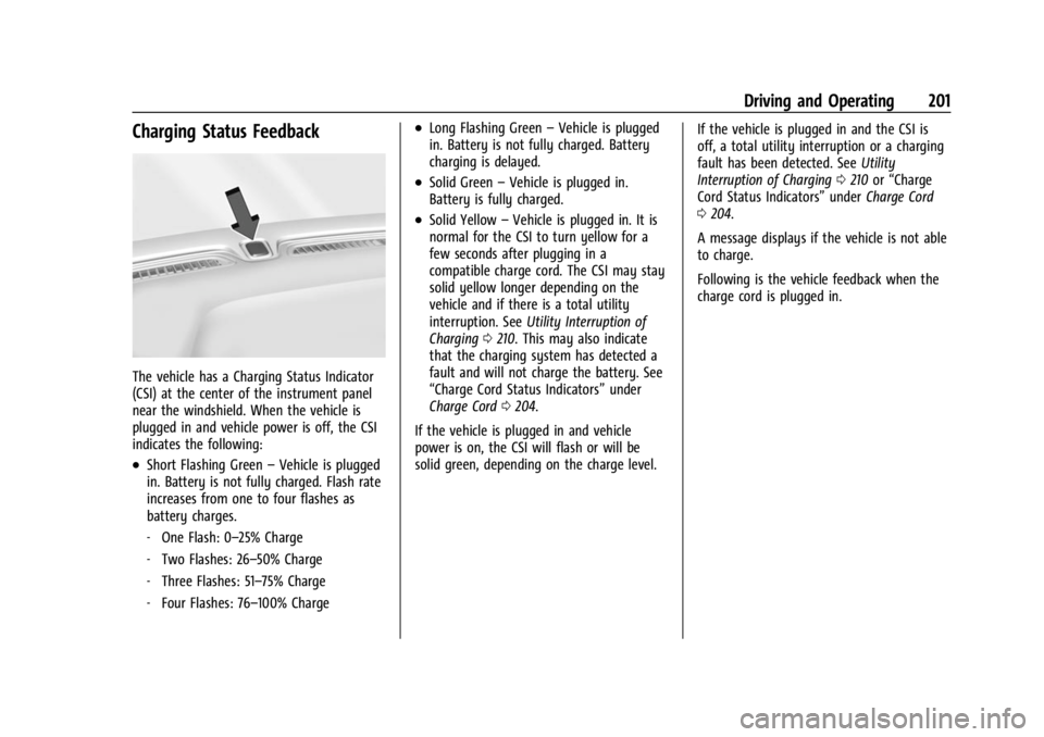
The vehicle has a Charging Status Indicator
(CSI) at the center of the instrument panel
near the windshield. When the vehicle is
plugged in and vehicle power is off, the CSI
indicates the following:
.Short Flashing Green–Vehicle is plugged
in. Battery is not fully charged. Flash rate
increases from one to four flashes as
battery charges.
‐ One Flash: 0–25% Charge
‐ Two Flashes: 26–50% Charge
‐ Three Flashes: 51–75% Charge
‐ Four Flashes: 76–100% Charge
.Long Flashing Green –Vehicle is plugged
in. Battery is not fully charged. Battery
charging is delayed.
.Solid Green –Vehicle is plugged in.
Battery is fully charged.
.Solid Yellow –Vehicle is plugged in. It is
normal for the CSI to turn yellow for a
few seconds after plugging in a
compatible charge cord. The CSI may stay
solid yellow longer depending on the
vehicle and if there is a total utility
interruption. See Utility Interruption of
Charging 0210. This may also indicate
that the charging system has detected a
fault and will not charge the battery. See
“Charge Cord Status Indicators” under
Charge Cord 0204.
If the vehicle is plugged in and vehicle
power is on, the CSI will flash or will be
solid green, depending on the charge level. If the vehicle is plugged in and the CSI is
off, a total utility interruption or a charging
fault has been detected. See
Utility
Interruption of Charging 0210 or“Charge
Cord Status Indicators” underCharge Cord
0 204.
A message displays if the vehicle is not able
to charge.
Following is the vehicle feedback when the
charge cord is plugged in.
Page 203 of 308
Chevrolet BOLT EV Owner Manual (GMNA-Localizing-U.S./Canada-
16404388) - 2023 - CRC - 3/7/22
202 Driving and Operating
Charging Status IndicatorSoundAction/Reason
Short Flashing Green (flash
rate increases from one to
four as the battery charges) One audible chirp
Vehicle is charging.
Long Flashing Green Two audible chirps Charging is delayed by Programmable Charging or by
a total utility interruption, if equipped. Charging will
begin later. See Utility Interruption of Charging 0210.
Short Flashing Green (one to
four flashes depending on
charge level) Two audible chirps
Vehicle is charging but will be delayed by
Programmable Charging at least once before the
charge is complete.
Solid Green None Charging is complete.
Yellow (upon plug-in) None Charge cord is OK and the vehicle is preparing to
charge.
Yellow (for extended time
period after plug-in) None
Charge cord is OK, but the vehicle is not charging.
This may be due to a total utility interruption, and
charging will begin later. This may also occur if the
vehicle has detected a high voltage charging system
fault. See Utility Interruption of Charging 0210 or
Service Vehicle Soon Light 085.
Short Flashing Green (from
one to four flashes
depending on charge level)
or Long Flashing Green Four audible chirps
Insufficient time to fully charge by departure time
due to the selected rate preference.
To increase the battery state of charge at the
departure time, perform a delayed charging override.
See Delayed Charging Override 0200.
Page 205 of 308
Chevrolet BOLT EV Owner Manual (GMNA-Localizing-U.S./Canada-
16404388) - 2023 - CRC - 3/7/22
204 Driving and Operating
Charge Cord
IMPORTANT SAFETY INSTRUCTIONS
This symbol indicates risk of electrical shock
if misused.
SeeRadio Frequency Statement 0286.
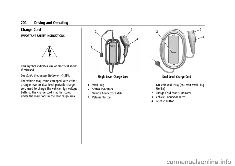
The vehicle may come equipped with either
a single level or dual level portable charge
cord used to charge the vehicle high voltage
battery. The charge cord may be stored
under the load floor in the rear cargo area.
Single Level Charge Cord
1. Wall Plug
2. Status Indicators
3. Vehicle Connector Latch
4. Release Button
Dual Level Charge Cord
1. 120 Volt Wall Plug (240 Volt Wall Plug Similar)
2. Charge Cord Status Indicator
3. Vehicle Connector Latch
4. Release Button
Page 211 of 308

Chevrolet BOLT EV Owner Manual (GMNA-Localizing-U.S./Canada-
16404388) - 2023 - CRC - 3/7/22
210 Driving and Operating
Lock Feature (Single Level Charge Cord)
A lock can be added to the vehicle plug for
additional security.
FCC Information
SeeRadio Frequency Statement 0286.
Utility Interruption of Charging
This vehicle will respond to requests through
the utility company to limit or completely
block electrical power grid usage. This
feature is inactive during DC charging.
A utility interruption of charging will
lengthen the vehicle charge time.
When electrical grid power is completely
blocked, the vehicle will delay charging until
the utility interruption has expired. The
vehicle should be left plugged in so that the
vehicle can automatically begin charging. Changing the charge mode to Immediate or
performing a delayed charging override will
not disable a utility interruption. Unplugging
and plugging the car back in will also not
disable a utility interruption.
A pop-up will appear in the infotainment
display while starting the vehicle following
any utility interruption. See
“Charging
Interrupted or Overridden Pop-Up” under
Programmable Charging 090.
A message will display on the instrument
cluster indicating that a utility interruption
has occurred.
Electrical Requirements for
Battery Charging
This vehicle is capable of being charged with
most standard vehicle charging equipment
complying with one or more of the
following:
.SAE J1772
.SAE J2847-2
.IEC 61851-1
.IEC 61851-22
.IEC 61851-23
.IEC 61851-24
.IEC 62196-1
.IEC 62196-2
.IEC 62196-3
The original equipment charge cord requires
a minimum circuit capacity as follows:
.120 volt system —15 amps
.240 volt system —40 amps (dual level
charge cord only)
For maximum level 2 charging rate, a
240 volt/48 amp charge station is required
(not included). The minimum circuit capacity
for this system is 60 amps.
Always follow the installation instructions
provided with your charging equipment and
all local electrical codes.
Caution
Do not use portable or stationary backup
generating equipment to charge the
vehicle. This may cause damage to the
vehicle's charging system. Only charge
the vehicle from utility supplied power.
Page 212 of 308
Chevrolet BOLT EV Owner Manual (GMNA-Localizing-U.S./Canada-
16404388) - 2023 - CRC - 3/7/22
Driving and Operating 211
Trailer Towing
General Towing Information
{Warning
Never tow a trailer with your vehicle.
It was not designed or intended to tow a
trailer.
Conversions and Add-Ons
Add-On Electrical Equipment
{Warning
The Data Link Connector (DLC) is used for
vehicle service and Emission Inspection/
Maintenance testing. SeeService Vehicle
Soon Light 085. A device connected to
the DLC —such as an aftermarket fleet
or driver-behavior tracking device —may
interfere with vehicle systems. This could
affect vehicle operation and cause a
crash. Such devices may also access
information stored in the vehicle’s
systems.
Caution
Some electrical equipment can damage
the vehicle or cause components to not
work and would not be covered by the
vehicle warranty. Always check with your
dealer before adding electrical equipment.
Add-on equipment can drain the vehicle's
12-volt battery, even if the vehicle is not
operating.
When adding electrical equipment, it should
only be connected using the accessory
power outlets. The maximum power that
can be supplied by one accessory power
outlet or spread across all three is 200 watts
or 15 amps. Exceeding 200 watts or 15 amps
may cause erratic vehicle operation.
The vehicle has an airbag system. Before
attempting to add anything electrical to the
vehicle, see Servicing the Airbag-Equipped
Vehicle 047 and
Adding Equipment to the Airbag-Equipped
Vehicle 047.
Page 213 of 308

Chevrolet BOLT EV Owner Manual (GMNA-Localizing-U.S./Canada-
16404388) - 2023 - CRC - 3/7/22
212 Vehicle Care
Vehicle Care
General Information
General Information . . . . . . . . . . . . . . . . . . . 213
California Perchlorate MaterialsRequirements . . . . . . . . . . . . . . . . . . . . . . . . 213
Accessories and Modifications . . . . . . . . . 213
Vehicle Checks
Doing Your Own Service Work . . . . . . . . . 213
Hood . . . . . . . . . . . . . . . . . . . . . . . . . . . . . . . . . . 214
Underhood Compartment Overview . . . 216
Cooling System . . . . . . . . . . . . . . . . . . . . . . . . 217
Washer Fluid . . . . . . . . . . . . . . . . . . . . . . . . . . 218
Brakes . . . . . . . . . . . . . . . . . . . . . . . . . . . . . . . . . 218
Brake Fluid . . . . . . . . . . . . . . . . . . . . . . . . . . . . 219
Battery - North America . . . . . . . . . . . . . . . 220
Park Brake and P (Park) Mechanism Check . . . . . . . . . . . . . . . . . . . . . . . . . . . . . . . . 222
Wiper Blade Replacement . . . . . . . . . . . . . 222
Windshield Replacement . . . . . . . . . . . . . . . 223
Gas Strut(s) . . . . . . . . . . . . . . . . . . . . . . . . . . . 224
Headlamp Aiming
Front Headlamp Aiming . . . . . . . . . . . . . . . 225
Bulb Replacement
Bulb Replacement . . . . . . . . . . . . . . . . . . . . . 225
Halogen Bulbs . . . . . . . . . . . . . . . . . . . . . . . . . 225
LED Lighting . . . . . . . . . . . . . . . . . . . . . . . . . . . 225
Back-Up Lamps . . . . . . . . . . . . . . . . . . . . . . . . 225 License Plate Lamp . . . . . . . . . . . . . . . . . . . . 226
Electrical System
High Voltage Devices and Wiring . . . . . . 227
Electrical System Overload . . . . . . . . . . . . . 227
Fuses and Circuit Breakers . . . . . . . . . . . . . 229
Underhood Compartment Fuse
Block . . . . . . . . . . . . . . . . . . . . . . . . . . . . . . . . 229
Instrument Panel Fuse Block . . . . . . . . . . . 232
Wheels and Tires
Tires . . . . . . . . . . . . . . . . . . . . . . . . . . . . . . . . . . . 234
All-Season Tires . . . . . . . . . . . . . . . . . . . . . . . . 235
Winter Tires . . . . . . . . . . . . . . . . . . . . . . . . . . . 235
Self-Sealing Tires . . . . . . . . . . . . . . . . . . . . . . 235
Tire Sidewall Labeling . . . . . . . . . . . . . . . . . 236
Tire Designations . . . . . . . . . . . . . . . . . . . . . . 236
Tire Terminology and Definitions . . . . . . 237
Tire Pressure . . . . . . . . . . . . . . . . . . . . . . . . . . 239
Tire Pressure Monitor System . . . . . . . . . 240
Tire Pressure Monitor Operation . . . . . . . 241
Tire Inspection . . . . . . . . . . . . . . . . . . . . . . . . 244
Tire Rotation . . . . . . . . . . . . . . . . . . . . . . . . . . 244
When It Is Time for New Tires . . . . . . . . 245
Buying New Tires . . . . . . . . . . . . . . . . . . . . . 246
Different Size Tires and Wheels . . . . . . . 247
Uniform Tire Quality Grading . . . . . . . . . . 247
Wheel Alignment and Tire Balance . . . . 248
Wheel Replacement . . . . . . . . . . . . . . . . . . . 248
Tire Chains . . . . . . . . . . . . . . . . . . . . . . . . . . . . 249
If a Tire Goes Flat . . . . . . . . . . . . . . . . . . . . . 249 Tire Sealant and Compressor Kit . . . . . . 250
Storing the Tire Sealant and
Compressor Kit . . . . . . . . . . . . . . . . . . . . . . 255
Jump Starting
Jump Starting - North America . . . . . . . . 256
Towing the Vehicle
Transporting a Disabled Vehicle . . . . . . . 258
Recreational Vehicle Towing . . . . . . . . . . 260
Appearance Care
Exterior Care . . . . . . . . . . . . . . . . . . . . . . . . . . 262
Interior Care . . . . . . . . . . . . . . . . . . . . . . . . . . . 265
Floor Mats . . . . . . . . . . . . . . . . . . . . . . . . . . . . 268