2023 ALFA ROMEO STELVIO wheel
[x] Cancel search: wheelPage 189 of 268

187
7. Open the liftgate and lift up the load floor using the handle.
8. Take the warning triangle and position it at a suitable distance from the vehicle to warn
oncoming vehicles.
9. Unscrew the locking plate and take out the compact spare tire and the air compressor.
Compact Spare Tire — If Equipped
10. Remove the damaged wheel by using the wheel wrench to loosen the bolts by one turn.
11. Position the jack under the vehicle, near the wheel to be changed, taking care not to
damage the plastic body panel.
12. Lift the extension lever on the wrench. Jacking Location13. Rotate the extension lever clockwise until the
round pin on the jack engages in the hole in
the lifting block located about 6 inches
(15 cm) from the outside edge of the body.
The lifting points are marked by triangles
visible on the plastic body panel.
Jacking Point Indicators
1 — Locking Plate
2 — Extension Lever
3 — Wrench Head
4 — Jack
5 — Lifting Block
CAUTION!
Do not attempt to raise the vehicle by jacking
on locations other than those indicated in the
Jacking Instructions for this vehicle.
23_GU_OM_EN_USC_t.book Page 187
Page 190 of 268

IN CASE OF EMERGENCY
188
14. Raise the vehicle by turning the jack screwclockwise, using the swivel wrench. Raise the
vehicle only until the tire just clears the
surface and enough clearance is obtained to
install the compact spare tire. Minimum tire
lift provides maximum stability.
15. Remove the five wheel bolts and take the wheel off.
16. Make sure the contact surfaces between compact spare tire and hub are clean so that
the fastening bolts will not come loose.
17. Fit the compact spare tire by inserting the first wheel bolt for two threads into the hole
closest to the valve.
18. Take the wheel wrench and tighten the wheel bolts.
19. Inflate the compact spare tire by removing the cap from its inflation valve and screwing
on the compressor inflation hose fitting. 20. Make sure that the switch on the compressor
is in the O (off) position, open the liftgate and
insert the plug into the power socket in the
cargo area, or on the center console and
start the engine. Place the on/off switch in
the I (on) position.
Attaching Compressor To Tire
21. Inflate the compact spare tire to a pressure of 43.5 psi (3 bar).
NOTE:
If spare tire is overinflated, be sure to lower the
psi in the tire to the recommended amount by
using the deflation button on the air compressor.
22. Operate the wheel wrench on the jack to lower the vehicle.
23. Remove the jack. 24. Use the wheel wrench to fully tighten the
bolts, passing alternately from one bolt to the
diagonally opposite one.
To obtain a more accurate reading, it is advisable
to check the pressure of the compact spare tire
on the pressure gauge with the compressor off.
NOTE:
Do not stow the deflated tire in the compact
spare tire location.
The compressor was designed for inflating the
compact spare tire. Do not use it for inflating
mattresses, rafts, etc.
NOTE:
Spare tires are intended for temporary use only.
Have the full-sized tire repaired or replaced, as
soon as possible.
WARNING!
Raising the vehicle higher than necessary can
make the vehicle less stable. It could slip off
the jack and hurt someone near it. Raise the
vehicle only enough to remove the tire.
CAUTION!
Be sure to mount the spare tire with the valve
stem facing outward. The vehicle could be
damaged if the spare tire is mounted
incorrectly.
6 — Air Compressor
7 — Pressure Gauge
8 — Power Button
WARNING!
To avoid the risk of forcing the vehicle off the
jack, do not tighten the wheel nuts fully until
the vehicle has been lowered. Failure to follow
this warning may result in serious injury.
WARNING!
A loose tire or jack thrown forward in a
collision or hard stop could endanger the
occupants of the vehicle. Always stow the jack
parts and the spare tire in the places provided.
Have the deflated (flat) tire repaired or
replaced immediately.
23_GU_OM_EN_USC_t.book Page 188
Page 191 of 268

189
TIRE SERVICE KIT —
IF EQUIPPED
DESCRIPTION
If a tire is punctured, you can make an emergency
repair using the Tire Service Kit located in the rear
storage area under the load platform.
1. Stop the vehicle in a position where you can repair the tire safely. You should be as far as
possible from the side of the road, and in a
position that is not dangerous for oncoming
traffic. Turn on the Hazard Warning Flashers,
remove the safety triangle from the luggage
compartment, and place it at a suitable
distance from the vehicle to make other
drivers aware of your presence.
2. Verify that the valve stem (on the wheel with the deflated tire) is in a position that is near
to the ground. This will allow the tire repair kit
hoses to reach the valve stem and keep the
tire service kit flat on the ground.
3. Place the gear selector in PARK (P).
4. Apply the electric park brake and turn the engine OFF. To access the Tire Service Kit, open the liftgate
and lift the load floor.
Load Floor
The Tire Service Kit consists of:
Sealant cartridge containing the sealing fluid
Filler Tube
Air compressor, complete with pressure gauge
and connectors
Adhesive label with the writing "Max. 50 mph
(80 km/h)”, to be attached in a position easily
visible to the driver (e.g. on the dashboard)
after repairing the tire
An instruction pamphlet for reference in
prompt and correct use of the Tire Service Kit,
which must be then given to the personnel
dealing with the sealant-treated tire
A pair of protective gloves
Some adapters, for inflating different elements
Tire Service Kit Components
NOTE:
The sealing fluid is effective with external
temperatures of between -40°F (-40°C) and
122°F (50°C).
The sealing fluid has an expiration date.
1 — Sealant Cartridge
2 — Filling Hose
3 — Adhesive Label
4 — Air Compressor
23_GU_OM_EN_USC_t.book Page 189
Page 192 of 268

IN CASE OF EMERGENCY
190
(Continued)
INFLATION PROCEDURE
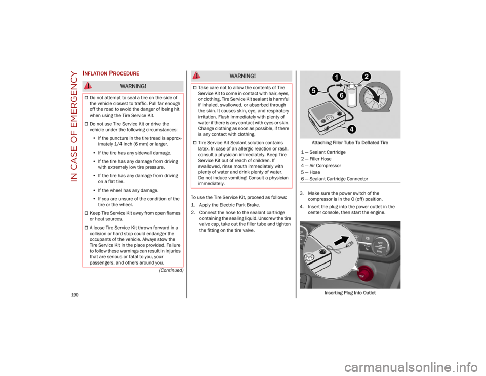
To use the Tire Service Kit, proceed as follows:
1. Apply the Electric Park Brake.
2. Connect the hose to the sealant cartridgecontaining the sealing liquid. Unscrew the tire
valve cap, take out the filler tube and tighten
the fitting on the tire valve. Attaching Filler Tube To Deflated Tire
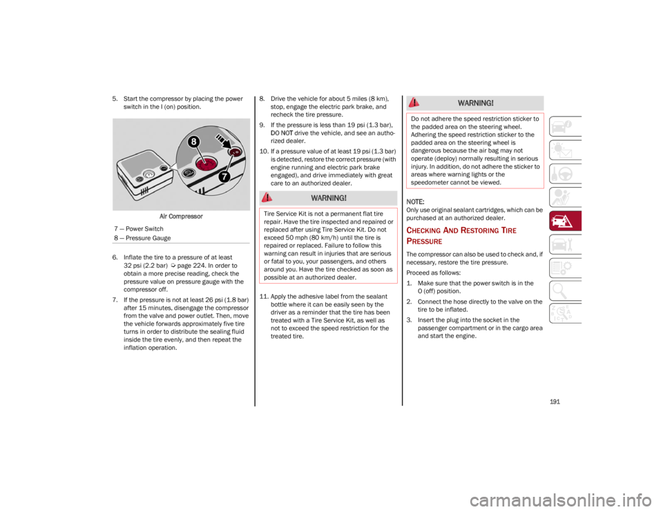
3. Make sure the power switch of the compressor is in the O (off) position.
4. Insert the plug into the power outlet in the center console, then start the engine.
Inserting Plug Into Outlet
WARNING!
Do not attempt to seal a tire on the side of
the vehicle closest to traffic. Pull far enough
off the road to avoid the danger of being hit
when using the Tire Service Kit.
Do not use Tire Service Kit or drive the
vehicle under the following circumstances:• If the puncture in the tire tread is approx-
imately 1/4 inch (6 mm) or larger.
• If the tire has any sidewall damage.
• If the tire has any damage from driving
with extremely low tire pressure.
• If the tire has any damage from driving
on a flat tire.
• If the wheel has any damage.
• If you are unsure of the condition of the
tire or the wheel.
Keep Tire Service Kit away from open flames
or heat sources.
A loose Tire Service Kit thrown forward in a
collision or hard stop could endanger the
occupants of the vehicle. Always stow the
Tire Service Kit in the place provided. Failure
to follow these warnings can result in injuries
that are serious or fatal to you, your
passengers, and others around you.
Take care not to allow the contents of Tire
Service Kit to come in contact with hair, eyes,
or clothing. Tire Service Kit sealant is harmful
if inhaled, swallowed, or absorbed through
the skin. It causes skin, eye, and respiratory
irritation. Flush immediately with plenty of
water if there is any contact with eyes or skin.
Change clothing as soon as possible, if there
is any contact with clothing.
Tire Service Kit Sealant solution contains
latex. In case of an allergic reaction or rash,
consult a physician immediately. Keep Tire
Service Kit out of reach of children. If
swallowed, rinse mouth immediately with
plenty of water and drink plenty of water.
Do not induce vomiting! Consult a physician
immediately.
WARNING!
1 — Sealant Cartridge
2 — Filler Hose
4 — Air Compressor
5 — Hose
6 — Sealant Cartridge Connector
23_GU_OM_EN_USC_t.book Page 190
Page 193 of 268

191
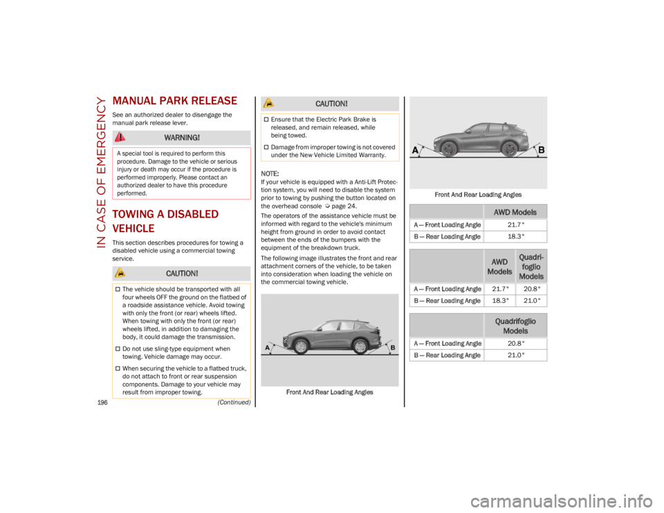
5. Start the compressor by placing the power switch in the I (on) position.
Air Compressor
6. Inflate the tire to a pressure of at least 32 psi (2.2 bar)
Ú
page 224. In order to
obtain a more precise reading, check the
pressure value on pressure gauge with the
compressor off.
7. If the pressure is not at least 26 psi (1.8 bar) after 15 minutes, disengage the compressor
from the valve and power outlet. Then, move
the vehicle forwards approximately five tire
turns in order to distribute the sealing fluid
inside the tire evenly, and then repeat the
inflation operation. 8. Drive the vehicle for about 5 miles (8 km),
stop, engage the electric park brake, and
recheck the tire pressure.
9. If the pressure is less than 19 psi (1.3 bar), DO NOT drive the vehicle, and see an autho -
rized dealer.
10. If a pressure value of at least 19 psi (1.3 bar) is detected, restore the correct pressure (with
engine running and electric park brake
engaged), and drive immediately with great
care to an authorized dealer.
11. Apply the adhesive label from the sealant bottle where it can be easily seen by the
driver as a reminder that the tire has been
treated with a Tire Service Kit, as well as
not to exceed the speed restriction for the
treated tire.
NOTE:
Only use original sealant cartridges, which can be
purchased at an authorized dealer.
CHECKING AND RESTORING TIRE
P
RESSURE
The compressor can also be used to check and, if
necessary, restore the tire pressure.
Proceed as follows:
1. Make sure that the power switch is in the
O (off) position.
2. Connect the hose directly to the valve on the tire to be inflated.
3. Insert the plug into the socket in the passenger compartment or in the cargo area
and start the engine.
7 — Power Switch
8 — Pressure Gauge
WARNING!
Tire Service Kit is not a permanent flat tire
repair. Have the tire inspected and repaired or
replaced after using Tire Service Kit. Do not
exceed 50 mph (80 km/h) until the tire is
repaired or replaced. Failure to follow this
warning can result in injuries that are serious
or fatal to you, your passengers, and others
around you. Have the tire checked as soon as
possible at an authorized dealer.
WARNING!
Do not adhere the speed restriction sticker to
the padded area on the steering wheel.
Adhering the speed restriction sticker to the
padded area on the steering wheel is
dangerous because the air bag may not
operate (deploy) normally resulting in serious
injury. In addition, do not adhere the sticker to
areas where warning lights or the
speedometer cannot be viewed.
23_GU_OM_EN_USC_t.book Page 191
Page 198 of 268

IN CASE OF EMERGENCY
196
(Continued)
MANUAL PARK RELEASE
See an authorized dealer to disengage the
manual park release lever.
TOWING A DISABLED
VEHICLE
This section describes procedures for towing a
disabled vehicle using a commercial towing
service.
NOTE:
If your vehicle is equipped with a Anti-Lift Protec-
tion system, you will need to disable the system
prior to towing by pushing the button located on
the overhead console
Ú
page 24.
The operators of the assistance vehicle must be
informed with regard to the vehicle's minimum
height from ground in order to avoid contact
between the ends of the bumpers with the
equipment of the breakdown truck.
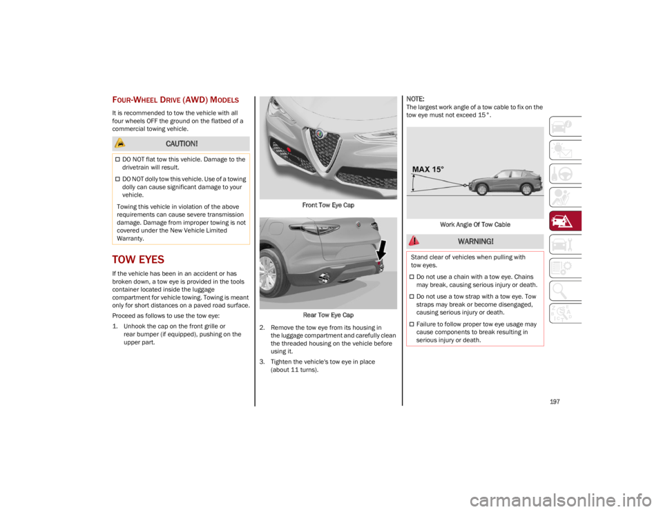
The following image illustrates the front and rear
attachment corners of the vehicle, to be taken
into consideration when loading the vehicle on
the commercial towing vehicle.
Front And Rear Loading Angles Front And Rear Loading Angles
WARNING!
A special tool is required to perform this
procedure. Damage to the vehicle or serious
injury or death may occur if the procedure is
performed improperly. Please contact an
authorized dealer to have this procedure
performed.
CAUTION!
The vehicle should be transported with all
four wheels OFF the ground on the flatbed of
a roadside assistance vehicle. Avoid towing
with only the front (or rear) wheels lifted.
When towing with only the front (or rear)
wheels lifted, in addition to damaging the
body, it could damage the transmission.
Do not use sling-type equipment when
towing. Vehicle damage may occur.
When securing the vehicle to a flatbed truck,
do not attach to front or rear suspension
components. Damage to your vehicle may
result from improper towing.
Ensure that the Electric Park Brake is
released, and remain released, while
being towed.
Damage from improper towing is not covered
under the New Vehicle Limited Warranty.
CAUTION!
AWD Models
A — Front Loading Angle 21.7°
B — Rear Loading Angle 18.3°
AWD
ModelsQuadri -
foglio
Models
A — Front Loading Angle 21.7° 20.8°
B — Rear Loading Angle 18.3° 21.0°
Quadrifoglio
Models
A — Front Loading Angle 20.8°
B — Rear Loading Angle 21.0°
23_GU_OM_EN_USC_t.book Page 196
Page 199 of 268

197
FOUR-WHEEL DRIVE (AWD) MODELS
It is recommended to tow the vehicle with all
four wheels OFF the ground on the flatbed of a
commercial towing vehicle.
TOW EYES
If the vehicle has been in an accident or has
broken down, a tow eye is provided in the tools
container located inside the luggage
compartment for vehicle towing. Towing is meant
only for short distances on a paved road surface.
Proceed as follows to use the tow eye:
1. Unhook the cap on the front grille orrear bumper (if equipped), pushing on the
upper part. Front Tow Eye Cap
Rear Tow Eye Cap
2. Remove the tow eye from its housing in the luggage compartment and carefully clean
the threaded housing on the vehicle before
using it.
3. Tighten the vehicle's tow eye in place (about 11 turns).
NOTE:
The largest work angle of a tow cable to fix on the
tow eye must not exceed 15°.
Work Angle Of Tow Cable
CAUTION!
DO NOT flat tow this vehicle. Damage to the
drivetrain will result.
DO NOT dolly tow this vehicle. Use of a towing
dolly can cause significant damage to your
vehicle.
Towing this vehicle in violation of the above
requirements can cause severe transmission
damage. Damage from improper towing is not
covered under the New Vehicle Limited
Warranty.
WARNING!
Stand clear of vehicles when pulling with
tow eyes.
Do not use a chain with a tow eye. Chains
may break, causing serious injury or death.
Do not use a tow strap with a tow eye. Tow
straps may break or become disengaged,
causing serious injury or death.
Failure to follow proper tow eye usage may
cause components to break resulting in
serious injury or death.
23_GU_OM_EN_USC_t.book Page 197
Page 209 of 268

207
NOTE:
Use care when filling under hood fluids such as
engine oil, windshield washer fluid, antifreeze
etc. to minimize spillage onto top of engine.
Any excess fluid that is spilled onto the top of
the engine should be removed using compressed
air or absorbent cloth.
NOTE:
The headlight washers are activated every
10 activations of the windshield washer.
NOTE:
The headlight washing system will not work if the
liquid level is low (situation indicated by the
symbol on the instrument cluster display
Ú
page 70). The windshield washer will keep
working.
On vehicles equipped with headlight washers,
there is a reference notch on the dipstick:
ONLY the windshield/rear window washer oper -
ates with the level below this reference.
BRAKE FLUID
Check that the fluid is at the maximum level. If the
fluid level in the tank is low, contact an authorized
dealer to have the system checked.
AUTOMATIC TRANSMISSION ACTIVATION
S
YSTEM OIL
The transmission control oil level should only be
checked at an authorized dealer.
USEFUL ADVICE FOR EXTENDING THE LIFE
O
F YOUR BATTERY
To avoid draining your battery and make it last
longer, observe the following instructions:
When you park the vehicle, ensure that the
doors and liftgate are closed properly to
prevent any lights from remaining on inside the
passenger's compartment.
Do not keep accessories (e.g. radio, hazard
warning lights, etc.) switched on for a long time
when the engine is not running.
Before performing any operation on the
electrical system, disconnect the negative
battery cable.
If you wish to install electrical accessories after
purchasing the vehicle that require permanent
electrical supply (e.g. alarm, etc.), or accessories
which influence the electrical supply
requirements, contact an authorized dealer,
who’s qualified staff will evaluate the overall
electrical consumption.
NOTE:
After the battery is disconnected, the steering
must be initialized. The Power Steering
Warning Light on the instrument cluster display
switches on to indicate this. To carry out this
procedure, simply turn the steering wheel all the
way from one end to the other, and then turn it
back to the central position.
BATTERY
The battery does not require the electrolyte to be
topped up with distilled water. A periodic check
carried out at an authorized dealer, however, is
necessary to check efficiency.
CAUTION!
If the charge level remains under 50% for a
long time, the battery may be damaged by
sulfation, reducing its capacity and efficiency
during the vehicle start. The battery is also
more prone to the risk of freezing (at
temperatures as high as 14°F (-10°C).
WARNING!
Battery acid is a corrosive solution and can
burn or even blind you. Do not allow battery
acid to contact your eyes, skin, or clothing.
Do not lean over a battery when attaching
clamps. If acid splashes in eyes or on skin,
flush the area immediately with large
amounts of water
Ú
page 192.
Battery gas is flammable and explosive.
Keep flame or sparks away from the battery.
Do not use a booster battery or any other
booster source with an output greater than
12 Volts. Do not allow cable clamps to touch
each other.
Battery posts, terminals, and related
accessories contain lead and lead
compounds. Wash hands after handling.
23_GU_OM_EN_USC_t.book Page 207