2023 ALFA ROMEO STELVIO headlights
[x] Cancel search: headlightsPage 140 of 268
STARTING AND OPERATING
138
CONNECTING THE ELECTRICAL SYSTEM
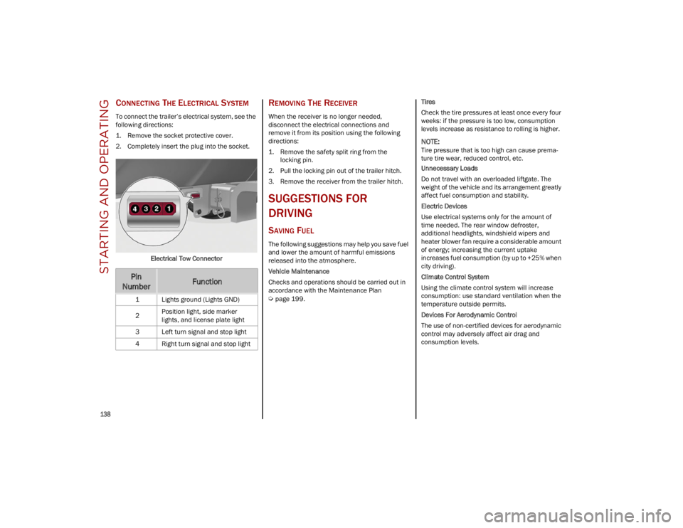
To connect the trailer’s electrical system, see the
following directions:
1. Remove the socket protective cover.
2. Completely insert the plug into the socket.Electrical Tow Connector
REMOVING THE RECEIVER
When the receiver is no longer needed,
disconnect the electrical connections and
remove it from its position using the following
directions:
1. Remove the safety split ring from thelocking pin.
2. Pull the locking pin out of the trailer hitch.
3. Remove the receiver from the trailer hitch.
SUGGESTIONS FOR
DRIVING
SAVING FUEL
The following suggestions may help you save fuel
and lower the amount of harmful emissions
released into the atmosphere.
Vehicle Maintenance
Checks and operations should be carried out in
accordance with the Maintenance Plan
Ú
page 199. Tires
Check the tire pressures at least once every four
weeks: if the pressure is too low, consumption
levels increase as resistance to rolling is higher.
NOTE:
Tire pressure that is too high can cause prema
-
ture tire wear, reduced control, etc.
Unnecessary Loads
Do not travel with an overloaded liftgate. The
weight of the vehicle and its arrangement greatly
affect fuel consumption and stability.
Electric Devices
Use electrical systems only for the amount of
time needed. The rear window defroster,
additional headlights, windshield wipers and
heater blower fan require a considerable amount
of energy; increasing the current uptake
increases fuel consumption (by up to +25% when
city driving).
Climate Control System
Using the climate control system will increase
consumption: use standard ventilation when the
temperature outside permits.
Devices For Aerodynamic Control
The use of non-certified devices for aerodynamic
control may adversely affect air drag and
consumption levels.
Pin
NumberFunction
1 Lights ground (Lights GND)
2 Position light, side marker
lights, and license plate light
3 Left turn signal and stop light
4 Right turn signal and stop light
23_GU_OM_EN_USC_t.book Page 138
Page 170 of 268

SAFETY
168
Do not drive your vehicle after the air bags have
deployed. If you are involved in another collision,
the air bags will not be in place to protect you.
NOTE:
Air bag covers may not be obvious in the
interior trim, but they will open during air bag
deployment.
After any collision, the vehicle should be taken
to an authorized dealer immediately.
Enhanced Accident Response System
In the event of an impact, if the communication
network remains intact, and the power remains
intact, depending on the nature of the event, the
Occupant Restraint Controller (ORC) will
determine whether to have the Enhanced
Accident Response System perform the following
functions:
Cut off fuel to the engine (if equipped)
Cut off battery power to the electric motor
(if equipped)
Flash hazard lights as long as the battery has
power
Turn on the interior lights, which remain on as
long as the battery has power or for
15 minutes from the intervention of the
Enhanced Accident Response System
Unlock the power door locks
Your vehicle may also be designed to perform any
of these other functions in response to the
Enhanced Accident Response System:
Turn off the Fuel Filter Heater, Turn off the
HVAC Blower Motor, Close the HVAC
Circulation Door
Cut off battery power to the: • Engine
• Electric Motor (if equipped)
• Electric power steering
• Brake booster
• Electric park brake
• Automatic transmission gear selector
• Horn
• Front wiper
• Headlamp washer pump (if equipped)
NOTE:
After an accident, remember to cycle the ignition
to the OFF position and remove the key from the
ignition switch to avoid draining the battery. Care -
fully check the vehicle for fuel leaks in the engine
compartment and on the ground near the engine
compartment and fuel tank before resetting the
system and starting the engine. If there are no
fuel leaks or damage to the vehicle electrical
devices (e.g. headlights) after an accident, reset
the system by following the procedure described
below. If you have any doubt, contact an autho -
rized dealer.
Enhanced Accident Response System
Reset Procedure
After the event occurs, when the system is active,
a message regarding fuel cutoff is displayed. Turn
the ignition switch from ignition ACC or ON/RUN
to ignition OFF. Carefully check the vehicle for
fuel leaks in the engine compartment and on the
ground near the engine compartment and fuel
tank before resetting the system and starting
the engine.
Depending on the nature of the event the left and
right turn signal lights, located in the instrument
panel, may both be blinking and will continue to
blink. In order to move your vehicle to the side of
the road, you must follow the system reset
procedure.
WARNING!
Deployed air bags and seat belt pretensioners
cannot protect you in another collision. Have
the air bags, seat belt pretensioners, and the
seat belt retractor assemblies replaced by an
authorized dealer immediately. Also, have the
Occupant Restraint Controller System serviced
as well.
23_GU_OM_EN_USC_t.book Page 168
Page 201 of 268

199
Correct servicing permits the performance of the
vehicle to be maintained over time, as well as
limited running costs and safeguarding the
efficiency of the safety systems.
SCHEDULED SERVICING
Correct servicing is crucial for guaranteeing a
long life for the vehicle under the best conditions.
For this reason, Alfa Romeo has planned a series
of checks and services for your vehicle at fixed
intervals based on distance and time, as
described in the Scheduled Servicing Plan.
Before each service, it is always necessary to
carefully follow the instructions in the Scheduled
Servicing Plan (e.g. periodically check level of
fluids, tire pressure, etc.).
Scheduled Servicing is offered by an authorized
dealer according to a set time schedule. If, during
each operation, in addition to the ones
scheduled, the need arises for further
replacements or repairs, these may be carried
out with the owner’s explicit consent only.
NOTE:
Scheduled Servicing intervals are required by the
manufacturer. Failure to have them carried out
may invalidate the New Vehicle Limited Warranty.
You are advised to inform an authorized dealer of
any small operating irregularities without waiting
for the next service.
PERIODIC CHECKS
Every month or every 620 miles (1,000 km) or
before long trips check and, if necessary, top off:
Engine coolant level.
Brake fluid level (if insufficient, see an
authorized dealer as soon as possible).
Windshield washer fluid level.
Tire inflation pressure and condition.
Operation of lighting system (headlights,
direction indicators, hazard warning lights,
etc.).
Operation of windshield washing/wiping
system and positioning/wear of wiper blades.
Inspect the CV/Universal joints.
Oil consumption of the engine depends on
conditions and driving style. For this reason, the
engine oil level must be checked every
1,860 miles (3,000 km), and top off if necessary;
for further information
Ú
page 205.
HEAVY USAGE OF THE VEHICLE
If the vehicle is used under one of the following
conditions:
Dusty roads.
Short, repeated journeys less than 4 miles
(7 km) at sub-zero outside temperatures.
Engine often idling or driving long distances at
low speeds or long periods of inactivity.
In the event of a long period of inactivity.
The following checks must be carried out more
often than indicated in the Scheduled Servicing
Plan:
Check cleanliness of hood and liftgate locks,
cleanliness and lubrication of linkage.
Visually inspect conditions of: engine,
transmission, pipes and hoses (exhaust/fuel
system/brakes) and rubber elements
(sleeves/bushes, etc.).
Check battery charge and battery fluid level
(electrolyte).
Visually inspect conditions of the accessory
drive belts.
Check and, if necessary, change engine oil and
replace oil filter.
Check and, if necessary, replace cabin air
filter.
Check and, if necessary, replace air cleaner.
Severe Duty All Models
Change engine oil at 4,000 miles (6,500 km) if the vehicle is operated in a dusty and off-road
environment or is operated predominately at idle
or only very low engine RPM. This type of vehicle
use is considered Severe Duty.
23_GU_OM_EN_USC_t.book Page 199
Page 202 of 268
SERVICING AND MAINTENANCE
200
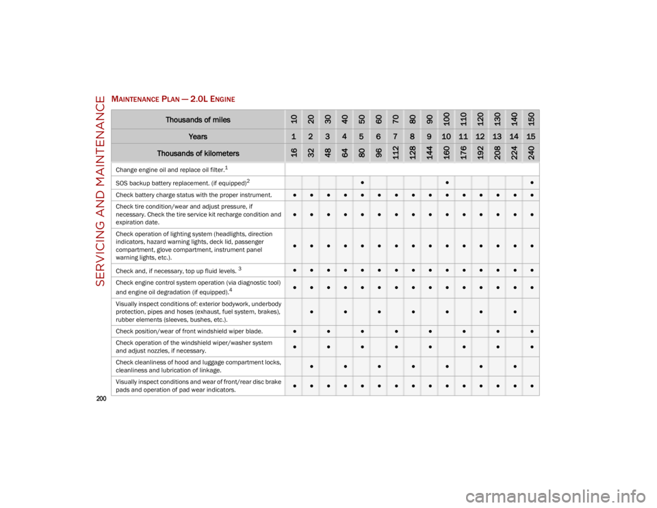
MAINTENANCE PLAN — 2.0L ENGINE
Thousands of miles102030405060708090100110120130140150
Years123456789101112131415
Thousands of kilometers163248648096112128144160176192208224240
Change engine oil and replace oil filter.1
SOS
backup battery replacement. (if equipped)
2 ●●●
Check battery charge status with the proper instrument.
●●●●●●●●●●●●●●●
Check tire condition/wear and adjust pressure, if
necessary. Check the tire service kit recharge condition and
expiration date.
●●●●●●●●●●●●●●●
Check operation of lighting system (headlights, direction
indicators, hazard warning lights, deck lid, passenger
compartment, glove compartment, instrument panel
warning lights, etc.).
●●●●●●●●●●●●●●●
Check and, if necessary, top up fluid levels.
3●●●●●●●●●●●●●●●
Check engine control system operation (via diagnostic tool)
and engine oil degradation (if equipped).
4●●●●●●●●●●●●●●●
Visually inspect conditions of: exterior bodywork, underbody
protection, pipes and hoses (exhaust, fuel system, brakes),
rubber elements (sleeves, bushes, etc.).
●●●●●●●
Check position/wear of front windshield wiper blade.●●●●●●●●
Check operation of the windshield wiper/washer system
and adjust nozzles, if necessary.
●●●●●●●●
Check cleanliness of hood and luggage compartment locks,
cleanliness and lubrication of linkage.
●●●●●●●
Visually inspect conditions and wear of front/rear disc brake
pads and operation of pad wear indicators.●●●●●●●●●●●●●●●
23_GU_OM_EN_USC_t.book Page 200
Page 204 of 268
SERVICING AND MAINTENANCE
202
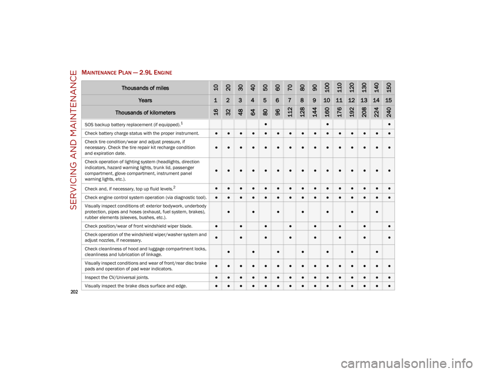
MAINTENANCE PLAN — 2.9L ENGINE
Thousands of miles102030405060708090100110120130140150
Years123456789101112131415
Thousands of kilometers163248648096112128144160176192208224240
SOS backup battery replacement (if equipped).1●●●
Check battery charge status with the proper instrument.
●●●●●●●●●●●●●●●
Check tire condition/wear and adjust pressure, if
necessary. Check the tire repair kit recharge condition
and expiration date.
●●●●●●●●●●●●●●●
Check operation of lighting system (headlights, direction
indicators, hazard warning lights, trunk lid, passenger
compartment, glove compartment, instrument panel
warning lights, etc.).
●●●●●●●●●●●●●●●
Check and, if necessary, top up fluid levels.
2●●●●●●●●●●●●●●●
Check engine control system operation (via diagnostic tool).
●●●●●●●●●●●●●●●
Visually inspect conditions of: exterior bodywork, underbody
protection, pipes and hoses (exhaust, fuel system, brakes),
rubber elements (sleeves, bushes, etc.).
●●●●●●●
Check position/wear of front windshield wiper blade.●●●●●●●●
Check operation of the windshield wiper/washer system and
adjust nozzles, if necessary.
●●●●●●●●
Check cleanliness of hood and luggage compartment locks,
cleanliness and lubrication of linkage.
●●●●●●●
Visually inspect conditions and wear of front/rear disc brake
pads and operation of pad wear indicators.●●●●●●●●●●●●●●●
Inspect the CV/Universal joints.
●●●●●●●●●●●●●●●
Visually inspect the brake discs surface and edge.
●●●●●●●●●●●●●●●
23_GU_OM_EN_USC_t.book Page 202
Page 206 of 268
SERVICING AND MAINTENANCE
204
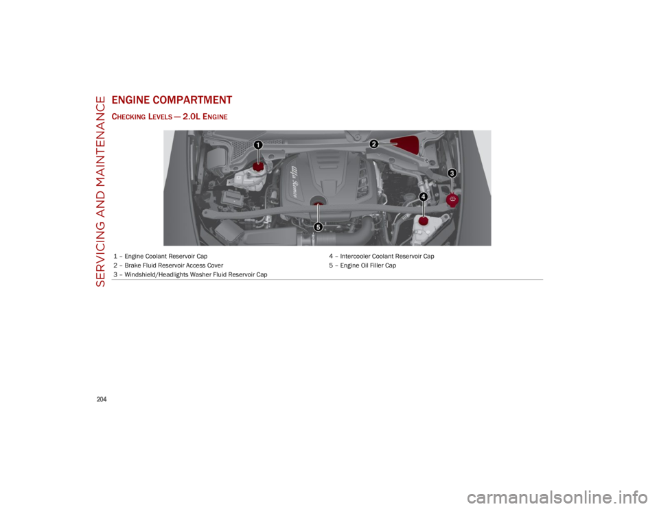
ENGINE COMPARTMENT
CHECKING LEVELS — 2.0L ENGINE
1 – Engine Coolant Reservoir Cap4 – Intercooler Coolant Reservoir Cap
2 – Brake Fluid Reservoir Access Cover 5 – Engine Oil Filler Cap
3 – Windshield/Headlights Washer Fluid Reservoir Cap
23_GU_OM_EN_USC_t.book Page 204
Page 222 of 268
SERVICING AND MAINTENANCE
220
BULB REPLACEMENT
General Instructions
Before replacing a bulb, check the contacts for oxidation.
Replace blown bulbs with others of the same type and power.
After replacing a headlight bulb, always check its alignment.
When a light is not working, check that the corresponding fuse is intact before changing the bulb.
NOTE:
In some particular climate conditions, such as low temperature, humidity, or after washing the vehicle, a thin condensation layer may form on the
internal surfaces of the front and rear headlights. This condensation will disappear after switching on the headlights.
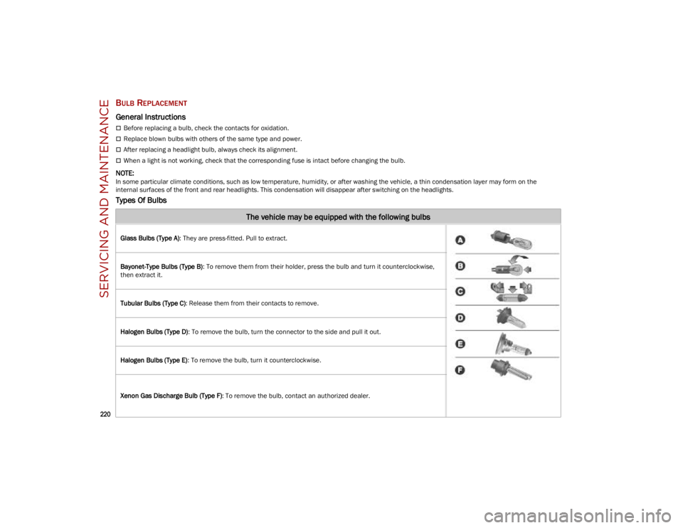
Types Of Bulbs
The vehicle may be equipped with the following bulbs
Glass Bulbs (Type A): They are press-fitted. Pull to extract.
Bayonet-Type Bulbs (Type B) : To remove them from their holder, press the bulb and turn it counterclockwise,
then extract it.
Tubular Bulbs (Type C) : Release them from their contacts to remove.
Halogen Bulbs (Type D) : To remove the bulb, turn the connector to the side and pull it out.
Halogen Bulbs (Type E) : To remove the bulb, turn it counterclockwise.
Xenon Gas Discharge Bulb (Type F) : To remove the bulb, contact an authorized dealer.
23_GU_OM_EN_USC_t.book Page 220
Page 223 of 268

221
Replacement Bulbs
*Only for basic version headlight with halogen main beam/dipped beam headlights
Replacing Exterior Bulbs
NOTE:
Only replace bulbs when the engine is off.
Also ensure that the engine is cold, to prevent the
risk of burns.
Front Light Cluster
Direction Indicators
Proceed with the following directions to change
bulbs:
1. Operating inside the engine compartment, locate the protective cover. Protective Cover Location
2. Remove protective cover. Protective Cover
Light bulbsTypePower
Front direction indicators*
PY24W24W
Rear Fog lights * H1155 W
Main beam headlights, front side lights/daylight running lights (DRL)* H1555/15W
Dipped beam headlights* H755W
Main beam/dipped beam headlights (Xenon gas discharge) D3S35W
Sun visor light 1.5CP2.1W
Glove compartment light W5W4W
Liftgate light W5W5W
Puddle lights (under door panel) W5W5W
23_GU_OM_EN_USC_t.book Page 221