2023 ALFA ROMEO GIULIA four wheel drive
[x] Cancel search: four wheel drivePage 92 of 248
STARTING AND OPERATING
90
Deactivation
To deactivate the sequential driving mode, bring
the gear selector back in position DRIVE (D)
(“automatic” driving mode).
NOTE:
To select the correct gear for maximum
deceleration (engine brake), just keep the gear
paddle pulled (–): the transmission goes to an
operating mode in which the vehicle can slow
down easily.
The vehicle will keep the gear selected by the
driver until the safety conditions allow it.
This means, for example, that the system will
try to prevent the engine from switching off,
automatically downshifting if the engine speed
is too low.
AUTOMATIC TRANSMISSION LIMP HOME
M
ODE
Transmission function is monitored electronically
for abnormal conditions. If a condition is detected
that could result in transmission damage,
Transmission Limp Home Mode is activated.
In this condition, the transmission stays in
FOURTH gear, regardless of the selected gear.
Positions PARK (P), REVERSE (R) and NEUTRAL
(N) still work. The symbol might light up in the instrument
cluster.
Temporary failure
In the event of a momentary problem, the
transmission can be reset to regain all forward
gears by performing the following steps:
1. Stop the vehicle.
2. Shift the transmission into PARK (P), if
possible. If not, shift the transmission to
NEUTRAL (N).
3. Push and hold the ignition until the engine turns off.
4. Wait for about 10 seconds, then restart the engine.
5. Shift into the desired gear range. If the problem is no longer detected, the transmis -
sion will return to normal operation.
NOTE:
Even if the transmission can be reset, we recom -
mend that you visit an authorized dealer at your
earliest possible convenience. An authorized
dealer has diagnostic equipment to determine if
the problem could reoccur. If the transmission
cannot be reset, service is required at an autho -
rized dealer.
BRAKE/TRANSMISSION SHIFT INTERLOCK
(BTSI) S
YSTEM
This vehicle is equipped with a BTSI system that
holds the gear selector in PARK (P) unless the
brakes are applied.
This system prevents you from moving the gear
selector from position PARK (P) unless the brakes
are applied. To shift the transmission out of PARK (P), the
ignition must be placed in the ON/RUN position
(engine running or not) and the brake pedal must
be pressed.
Brake/Transmission Shift Interlock Disabling
Only if strictly necessary (e.g. pushing the vehicle,
conveyor vehicle washing systems), place the
vehicle in the NEUTRAL (N) position when
stopping the engine. See the following steps:
1. Vehicle at a standstill.
2. NEUTRAL (N) mode activated.
3. Push the ignition button for at least three
seconds.
The automatic parking brake engagement
function when the engine is stopped can also be
deactivated on the Information and
Entertainment system by selecting the following
functions on the main menu: “Settings”, “Driver
Assistance” and “Automatic Parking Brake”.
IMPORTANT NOTES
Failure to comply with the following may damage
the transmission:
Shift into PARK (P) mode only with the vehicle
at a standstill.
Select REVERSE (R) mode, or pass from
REVERSE to another mode only with the
vehicle at a standstill and engine idling.
Do not change between PARK (P), REVERSE
(R), NEUTRAL (N) or DRIVE (D) modes with
engine running at a speed above idling.
Before activating any transmission operating
mode, fully press the brake pedal.
WARNING!
Do not downshift for additional engine braking
on a slippery surface. The drive wheels could
lose their grip and the vehicle could skid,
causing a collision or personal injury.
23_GA_OM_EN_USC_t.book Page 90
Page 103 of 248

101
Activating Adaptive Cruise Control (ACC)
The minimum set speed for the ACC system is
19 mph (30 km/h) and the maximum is 110 mph
(180 km/h).
The system cannot be activated:
When pressing the brake pedal.
When the brakes are overheated.
When the Electric Park Brake has been
operated.
When either PARK, REVERSE or NEUTRAL is
engaged.
When the engine RPM is above a maximum
threshold.
When the vehicle speed is not within the
operational speed range.
When the Electronic Stability Control (ESC) (or
Anti-Lock Brake System (ABS) or other stability
control systems) are operating or have just
operated.
When the ESC system is off.
When the Forward Collision Warning system (if
equipped) is braking automatically.
In the event of a system failure.
When the engine is off.
In case of obstruction of the radar sensor (in
this case the bumper area where it is located
must be cleaned).
If the system is set, the conditions described
above also cause a cancellation or deactivation
of the system. These situations may vary
according to the conditions.
NOTE:
The system will not be deactivated when speeds
higher than those set are reached by pressing the
accelerator pedal above 110 mph (180 km/h). In
these situations, the system may not work
correctly and it is recommended to deactivate it.
The driver should always obey traffic laws and
speed limits. Never drive above applicable speed
limit restrictions.
To Activate/Deactivate
The system has four operating states:
Enabled (speed not set)
Activated (speed set)
Paused
Deactivated
To Activate
To enable the system, push and release the on/
off button located on the left side on the steering
wheel.
On/Off Button
•
Cannot take street, traffic, and weather
conditions into account, and may be limited upon adverse sight distance conditions.
• Does not always fully recognize complex
driving conditions, which can result in wrong or missing distance warnings.
• Will bring the vehicle to a complete stop
while following a vehicle ah ead and hold
the ve
hicle for approximately two
minutes in the stop position. If the vehicle ahead does not start movingwithin two minutes, the parking brakewill be activated and the ACC system will be canceled.
You should switch off the ACC system:
• When driving in fog, heavy rain, heavy
snow, sleet, heavy traffic, and complex driving situations (i.e., in highwayconstruction zones).
• When entering a turn lane or highway
off-ramp; w hen driving on roads that are
win d
ing, icy, snow-covered, slippery, or
have steep uphill or downhill slopes.
• When circumstances do not allow safe
driving at a constant speed.
WARNING!
23_GA_OM_EN_USC_t.book Page 101
Page 108 of 248
STARTING AND OPERATING
106
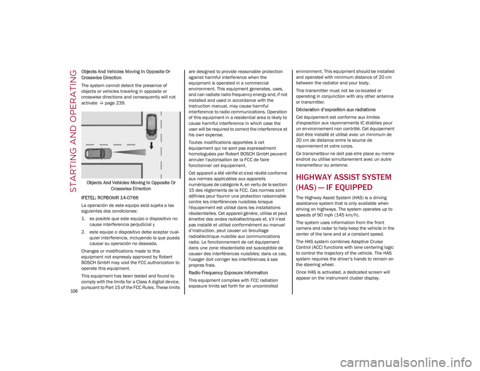
Objects And Vehicles Moving In Opposite Or
Crosswise Direction
The system cannot detect the presence of
objects or vehicles traveling in opposite or
crosswise directions and consequently will not
activate
Ú
page 239.
Objects And Vehicles Moving In Opposite Or Crosswise Direction
IFETEL: RCPBOMR 14-0766
La operación de este equipo está sujeta a las
siguientes dos condiciones:
1. es posible que este equipo o dispositivo no cause interferencia perjudicial y
2. este equipo o dispositivo debe aceptar cual -
quier interferencia, incluyendo la que pueda
causar su operación no deseada.
Changes or modifications made to this
equipment not expressly approved by Robert
BOSCH GmbH may void the FCC authorization to
operate this equipment.
This equipment has been tested and found to
comply with the limits for a Class A digital device,
pursuant to Part 15 of the FCC Rules. These limits are designed to provide reasonable protection
against harmful interference when the
equipment is operated in a commercial
environment. This equipment generates, uses,
and can radiate radio frequency energy and, if not
installed and used in accordance with the
instruction manual, may cause harmful
interference to radio communications. Operation
of this equipment in a residential area is likely to
cause harmful interference in which case the
user will be required to correct the interference at
his own expense.
Toutes modifications apportées à cet
équipement qui ne sont pas expressément
homologuées par Robert BOSCH GmbH peuvent
annuler l'autorisation de la FCC de faire
fonctionner cet équipement.
Cet appareil a été vérifié et s'est révélé conforme
aux normes applicables aux appareils
numériques de catégorie A, en vertu de la section
15 des règlements de la FCC. Ces normes sont
définies pour fournir une protection raisonnable
contre les interférences nuisibles lorsque
l'équipement est utilisé dans les installations
résidentielles. Cet appareil génère, utilise et peut
émettre des ondes radioélectriques et, s'il n'est
pas installé et utilisé conformément au manuel
d’instruction, peut causer un brouillage
radioélectrique nuisible aux communications
radio. Le fonctionnement de cet équipement
dans une zone résidentielle est susceptible de
causer des interférences nuisibles; dans ce cas,
l'usager doit corriger les interférences à ses
propres frais.
Radio Frequency Exposure Information
This equipment complies with FCC radiation
exposure limits set forth for an uncontrolled
environment. This equipment should be installed
and operated with minimum distance of 20 cm
between the radiator and your body.
This transmitter must not be co-located or
operating in conjunction with any other antenna
or transmitter.
Déclaration d’exposition aux radiations
Cet équipement est conforme aux limites
d'exposition aux rayonnements IC établies pour
un environnement non contrôlé. Cet équipement
doit être installé et utilisé avec un minimum de
20 cm de distance entre la source de
rayonnement et votre corps.
Ce transmetteur ne doit pas etre place au meme
endroit ou utilise simultanement avec un autre
transmetteur ou antenne.
HIGHWAY ASSIST SYSTEM
(HAS) — IF EQUIPPED
The Highway Assist System (HAS) is a driving
assistance system that is only available when
driving on highways. The system operates up to
speeds of 90 mph (145 km/h).
The system uses information from the front
camera and radar to help keep the vehicle in the
center of the lane and at a constant speed.
The HAS system combines Adaptive Cruise
Control (ACC) functions with lane centering logic
to control the trajectory of the vehicle. The HAS
system requires the driver’s hands to remain on
the steering wheel.
Once HAS is activated, a dedicated screen will
appear on the instrument cluster display.
23_GA_OM_EN_USC_t.book Page 106
Page 128 of 248
STARTING AND OPERATING
126
A Month-Day-Hour (MDH) number is included on
this label and indicates the Month, Day and Hour
of manufacture. The bar code that appears on
the bottom of the label is your VIN.
Gross Vehicle Weight Rating (GVWR)
The GVWR is the total permissible weight of your
vehicle including driver, passengers, vehicle,
options and cargo. The label also specifies
maximum capacities of front and rear axle
systems (GAWR). Total load must be limited so
GVWR and front and rear GAWR are not
exceeded.
Payload
The payload of a vehicle is defined as the
allowable load weight a truck can carry, including
the weight of the driver, all passengers, options
and cargo.
Gross Axle Weight Rating (GAWR)
The GAWR is the maximum permissible load on
the front and rear axles. The load must be
distributed in the cargo area so that the GAWR of
each axle is not exceeded.
Each axle GAWR is determined by the
components in the system with the lowest load
carrying capacity (axle, springs, tires or wheels).
Heavier axles or suspension components
sometimes specified by purchasers for increased
durability do not necessarily increase the
vehicle's GVWR.
Tire Size
The tire size on the Vehicle Certification Label
represents the actual tire size on your vehicle.
Replacement tires must be equal to the load
capacity of this tire size.
Rim Size
This is the rim size that is appropriate for the tire
size listed.
Inflation Pressure
This is the cold tire inflation pressure for your
vehicle for all loading conditions up to full GAWR.
Curb Weight
The curb weight of a vehicle is defined as the total
weight of the vehicle with all fluids, including
vehicle fuel, at full capacity conditions, and with
no occupants or cargo loaded into the vehicle.
The front and rear curb weight values are
determined by weighing your vehicle on a
commercial scale before any occupants or cargo
are added.
Loading
The actual total weight and the weight of the front
and rear of your vehicle at the ground can best be
determined by weighing it when it is loaded and
ready for operation.
The entire vehicle should first be weighed on a
commercial scale to ensure that the GVWR has
not been exceeded. The weight on the front and
rear of the vehicle should then be determined
separately to be sure that the load is properly
distributed over the front and rear axle. Weighing
the vehicle may show that the GAWR of either the
front or rear axles has been exceeded but the
total load is within the specified GVWR. If so,
weight must be shifted from front to rear or rear
to front as appropriate until the specified weight
limitations are met. Store the heavier items down
low and be sure that the weight is distributed
equally. Stow all loose items securely before
driving.Improper weight distributions can have an
adverse effect on the way your vehicle steers and
handles and the way the brakes operate.
TRAILER TOWING
Trailer towing is not recommended for this
vehicle.
SUGGESTIONS FOR
DRIVING
SAVING FUEL
The following are some suggestions which may
help you save fuel and lower the amount of
harmful emissions released into the atmosphere.
Vehicle Maintenance
Checks and operations should be carried out in
accordance with the Maintenance Plan
Ú
page 182.
Tires
Check the tire pressures at least once every four
weeks: if the pressure is too low, consumption
levels increase as resistance to rolling is higher.
WARNING!
Do not load your vehicle any heavier than the
GVWR or the maximum front and rear GAWR. If
you do, parts on your vehicle can break, or it
can change the way your vehicle handles. This
could cause you to lose control. Overloading
can shorten the life of your vehicle.
23_GA_OM_EN_USC_t.book Page 126
Page 145 of 248

143
Insufficient Tire Pressure Indication
If an insufficient pressure value is detected on
one or more tires, the Tire Pressure Monitoring
System Warning Light in the instrument cluster
will display alongside the dedicated messages,
the system will highlight the tire or tires with
insufficient pressure graphically, and an acoustic
signal will be emitted.In this case, stop the vehicle, check the inflation
pressure of each tire, and inflate the necessary
tire or tires to the correct cold inflation pressure
value, shown on the display or in the dedicated
TPMS menu.
TPMS Temporarily Disabled:
TPMS Check Message
When a system fault is detected, the Tire
Pressure Monitoring System Warning Light will
flash on and off for 75 seconds, and then remain
on solid. The system fault will also sound a chime.
If the ignition is cycled, this sequence will repeat,
provided that the system fault still exists. The Tire
Pressure Monitoring System Warning Light will
turn off when the fault condition no longer exists.
A system fault can occur due to any of the
following:
Jamming due to electronic devices or driving
next to facilities emitting the same radio
frequencies as the TPMS sensors.
Installing some form of aftermarket window
tinting that affects radio wave signals.
Packed snow or ice around the wheels or
wheel housings.
Using tire chains on the vehicle.
Using wheels/tires not equipped with TPMS
sensors.
After the punctured tire has been repaired with
the original tire sealant contained in the tire kit,
the previous condition must be restored so that
the Tire Pressure Monitoring System Warning
Light is off during normal driving.
TPMS Deactivation
The TPMS can be deactivated by replacing all four
wheel and tire assemblies (road tires) with wheel and tire assemblies that do not have TPMS
sensors, such as when installing winter wheel
and tire assemblies on your vehicle.
To deactivate the TPMS, first replace all four
wheel and tire assemblies (road tires) with tires
not equipped with Tire Pressure Monitoring
System sensors. Then, drive the vehicle for
20 minutes above 15 mph (24 km/h). The TPMS
will chime, the Tire Pressure Monitoring System
Warning Light will flash on and off for 75 seconds
and then remain on. The instrument cluster will
display the “SERVICE TPM SYSTEM” message
and then display dashes (--) in place of the
pressure values.
Beginning with the next ignition switch cycle, the
TPMS will no longer chime or display the
“SERVICE TPM SYSTEM” message in the
instrument cluster. Instead, dashes (--) will
remain in place of the pressure values.
To reactivate the TPMS, replace all four wheel
and tire assemblies (road tires) with tires
equipped with TPMS sensors. Then, drive the
vehicle for up to 20 minutes above 15 mph
(24 km/h). The TPMS will chime, the Tire
Pressure Monitoring System Warning Light will
flash on and off for 75 seconds and then turn off.
The instrument cluster will display the “SERVICE
TPM SYSTEM” message and then display
pressure values in place of the dashes. On the
next ignition switch cycle the "SERVICE TPM
SYSTEM" message will no longer be displayed, as
long as no system fault exists.
NOTE:
The TPMS is not intended to replace normal
tire care and maintenance, or to provide
warning of a tire failure or condition.
CAUTION!
The TPMS has been optimized for the original
equipment tires and wheels. TPMS pressures
and warning have been established for the
tire size equipped on your vehicle.
Undesirable system operation or sensor
damage may result when using replacement
equipment that is not of the same size, type,
and/or style. The TPMS sensor is not
designed for use on aftermarket wheels and
may contribute to a poor overall system
performance or sensor damage. Customers
are encouraged to use Original Equipment
Manufacturer (OEM) wheels to ensure proper
TPMS feature operation.
Using aftermarket tire sealants may cause the
Tire Pressure Monitoring System (TPMS)
sensor to become inoperable. After using an
aftermarket tire sealant it is recommended
that you take your vehicle to an authorized
dealer to have your sensor function checked.
After inspecting or adjusting the tire pressure
always reinstall the valve stem cap. This will
prevent moisture and dirt from entering the
valve stem, which could damage the TPMS
sensor.
23_GA_OM_EN_USC_t.book Page 143
Page 152 of 248

SAFETY
150
Air Bag System Components
Occupant Restraint Controller (ORC)
Air Bag Warning Light
Steering Wheel and Column
Instrument Panel
Knee Impact Bolsters
Driver and Front Passenger Air Bags
Seat Belt Buckle Switch
Supplemental Side Air Bags
Supplemental Knee Air Bags
Front and Side Impact Sensors
Seat Belt Pretensioners
Seat Track Position Sensors
Air Bag Warning Light
The Occupant Restraint Controller
(ORC) monitors the readiness of the
electronic parts of the air bag system
whenever the ignition switch is in the
START or ON/RUN position. If the ignition switch
is in the OFF position or in the ACC position, the
air bag system is not on and the air bags will not
inflate.
The ORC contains a backup power supply system
that may deploy the air bag system even if the
battery loses power or it becomes disconnected
prior to deployment.
The ORC turns on the Air Bag Warning Light in the
instrument panel for approximately four to eight
seconds for a self-check when the ignition switch
is first in the ON/RUN position. After the
self-check, the Air Bag Warning Light will turn off.
If the ORC detects a malfunction in any part of the
system, it turns on the Air Bag Warning Light, either momentarily or continuously. A single
chime will sound to alert you if the light comes on
again after initial startup.
The ORC also includes diagnostics that will
illuminate the instrument panel Air Bag Warning
Light if a malfunction is detected that could affect
the air bag system. The diagnostics also record
the nature of the malfunction. While the air bag
system is designed to be maintenance free, if any
of the following occurs, have an authorized dealer
service the air bag system immediately.
The Air Bag Warning Light does not come on
during the four to eight seconds when the
ignition switch is first in the ON/RUN position.
The Air Bag Warning Light remains on after the
four to eight-second interval.
The Air Bag Warning Light comes on intermit
-
tently or remains on while driving.
NOTE:
If the speedometer, tachometer, or any engine
related gauges are not working, the Occupant
Restraint Controller (ORC) may also be disabled.
In this condition the air bags may not be ready to
inflate for your protection. Have an authorized
dealer service the air bag system immediately.
Redundant Air Bag Warning Light
If a fault with the Air Bag Warning Light
is detected, which could affect the
Supplemental Restraint System (SRS),
the Redundant Air Bag Warning Light
will illuminate on the instrument panel. The
Redundant Air Bag Warning Light will stay on until
the fault is cleared. In addition, a single chime will
sound to alert you that the Redundant Air Bag
Warning Light has come on and a fault has been
detected. If the Redundant Air Bag Warning Light
comes on intermittently or remains on while
driving have an authorized dealer service the
vehicle immediately.
For additional information regarding the
Redundant Air Bag Warning Light, see
Ú
page 70.
Front Air Bags
This vehicle has front air bags and lap/shoulder
belts for both the driver and front passenger. The
front air bags are a supplement to the seat belt
restraint systems. The driver front air bag is
mounted in the center of the steering wheel. The
passenger front air bag is mounted in the
instrument panel, above the glove compartment.
The words “SRS AIRBAG” or “AIRBAG” are
embossed on the air bag covers.
WARNING!
Ignoring the Air Bag Warning Light in your
instrument panel could mean you won’t have
the air bag system to protect you in a collision.
If the light does not come on as a bulb check
when the ignition is first turned on, stays on
after you start the vehicle, or if it comes on as
you drive, have an authorized dealer service
the air bag system immediately.
23_GA_OM_EN_USC_t.book Page 150
Page 181 of 248
179
(Continued)
MANUAL PARK RELEASE
See an authorized dealer to disengage the
manual park release lever.
TOWING A DISABLED
VEHICLE
This section describes procedures for towing a
disabled vehicle using a commercial towing
service.The operators of the assistance vehicle must be
informed with regard to the vehicle's minimum
height from ground in order to avoid contact
between the ends of the fascia/bumper with the
equipment of the breakdown truck.
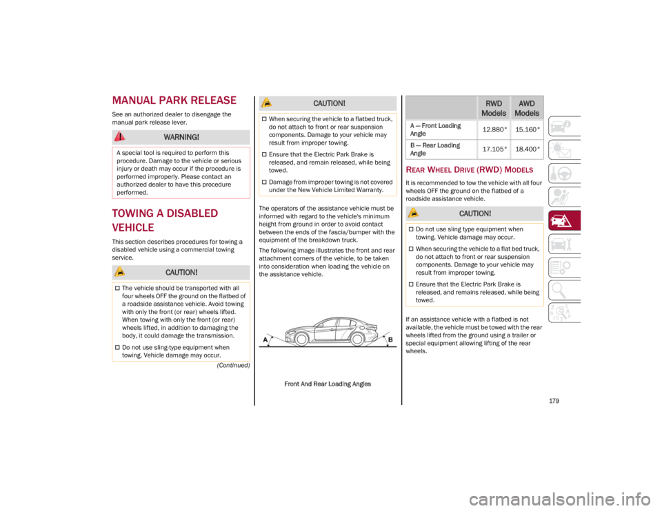
The following image illustrates the front and rear
attachment corners of the vehicle, to be taken
into consideration when loading the vehicle on
the assistance vehicle.
Front And Rear Loading Angles
REAR WHEEL DRIVE (RWD) MODELS
It is recommended to tow the vehicle with all four
wheels OFF the ground on the flatbed of a
roadside assistance vehicle.
If an assistance vehicle with a flatbed is not
available, the vehicle must be towed with the rear
wheels lifted from the ground using a trailer or
special equipment allowing lifting of the rear
wheels.
WARNING!
A special tool is required to perform this
procedure. Damage to the vehicle or serious
injury or death may occur if the procedure is
performed improperly. Please contact an
authorized dealer to have this procedure
performed.
CAUTION!
The vehicle should be transported with all
four wheels OFF the ground on the flatbed of
a roadside assistance vehicle. Avoid towing
with only the front (or rear) wheels lifted.
When towing with only the front (or rear)
wheels lifted, in addition to damaging the
body, it could damage the transmission.
Do not use sling-type equipment when
towing. Vehicle damage may occur.
When securing the vehicle to a flatbed truck,
do not attach to front or rear suspension
components. Damage to your vehicle may
result from improper towing.
Ensure that the Electric Park Brake is
released, and remain released, while being
towed.
Damage from improper towing is not covered
under the New Vehicle Limited Warranty.
CAUTION!RWD
ModelsAWD
Models
A — Front Loading
Angle 12.880° 15.160°
B — Rear Loading
Angle 17.105° 18.400°
CAUTION!
Do not use sling type equipment when
towing. Vehicle damage may occur.
When securing the vehicle to a flat bed truck,
do not attach to front or rear suspension
components. Damage to your vehicle may
result from improper towing.
Ensure that the Electric Park Brake is
released, and remains released, while being
towed.
23_GA_OM_EN_USC_t.book Page 179
Page 182 of 248
IN CASE OF EMERGENCY
180
(Continued)
ALL WHEEL DRIVE (AWD) MODELS
It is recommended to tow the vehicle with all four
wheels OFF the ground on the flatbed of a
roadside assistance vehicle.
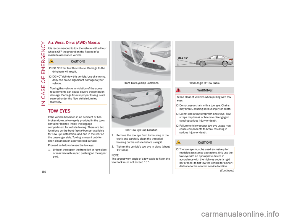
TOW EYES
If the vehicle has been in an accident or has
broken down, a tow eye is provided in the tools
container located inside the luggage
compartment for vehicle towing. There are two
locations on the front fascia/bumper available
for Tow Eye installation, and one in the rear on
the passenger side. Towing is meant only for
short distances on a paved road surface.
Proceed as follows to use the tow eye:
1. Unhook the cap on the front (left or right side) or rear fascia/bumper, pushing on the upper
part. Front Tow Eye Cap Locations
Rear Tow Eye Cap Location
2. Remove the tow eye from its housing in the trunk and carefully clean the threaded
housing on the vehicle before using it.
3. Tighten the vehicle's tow eye in place (about 11 turns).
NOTE:
The largest work angle of a tow cable to fix on the
tow hook must not exceed 15°. Work Angle Of Tow Cable
CAUTION!
DO NOT flat tow this vehicle. Damage to the
drivetrain will result.
DO NOT dolly tow this vehicle. Use of a towing
dolly can cause significant damage to your
vehicle.
Towing this vehicle in violation of the above
requirements can cause severe transmission
damage. Damage from improper towing is not
covered under the New Vehicle Limited
Warranty.
WARNING!
Stand clear of vehicles when pulling with tow
eyes.
Do not use a chain with a tow eye. Chains
may break, causing serious injury or death.
Do not use a tow strap with a tow eye. Tow
straps may break or become disengaged,
causing serious injury or death.
Failure to follow proper tow eye usage may
cause components to break resulting in
serious injury or death.
CAUTION!
The tow eye must be used exclusively for
roadside assistance operations. Only use the
tow eye with an appropriate device in
accordance with the highway code (a rigid
bar or rope) to flat tow the vehicle for a short
distance to the nearest service location.
23_GA_OM_EN_USC_t.book Page 180