2022 YAMAHA YZF-R7 Fuel tank
[x] Cancel search: Fuel tankPage 6 of 100

Table of contentsSafety information ............................ 1-1
Description ....................................... 2-1
Left view ......................................... 2-1
Right view ....................................... 2-2
Controls and instruments ............... 2-3
Instrument an d control functions ... 3-1
Immobilizer system......................... 3-1
Main switch/steering lock............... 3-2
Indicator lights and warning lights............................................ 3-3
Multi-function meter unit ................ 3-6
Handlebar switches ...................... 3-12
Clutch lever .................................. 3-14
Shift pedal .................................... 3-14
Brake lever.................................... 3-14
Brake pedal .................................. 3-15
ABS .............................................. 3-15
Fuel tank cap ................................ 3-16
Fuel ............................................... 3-17
Fuel tank overflow hose ............... 3-18
Catalytic converter ....................... 3-19
Seats ............................................ 3-19
Rear view mirrors.......................... 3-21
Adjusting the front fork ................. 3-22
Adjusting the shock absorber assembly ................................... 3-24
Auxiliary DC connector ................. 3-26
Sidestand ..................................... 3-26
Ignition circuit cut-off system ....... 3-27 For your safety – pre-operation
checks
............................................... 4-1
Operation an d important ri din g
points ................................................. 5-1
Engine break-in ............................... 5-1
Starting the engine .......................... 5-2
Shifting ............................................ 5-3
Tips for reducing fuel consumption ................................ 5-4
Parking ............................................ 5-4
Perio dic maintenance an d
a d justment ........................................ 6-1
Tool kits........................................... 6-2
Periodic maintenance charts .......... 6-3
Periodic maintenance chart for the emission control system .............. 6-3
General maintenance and lubrication chart ........................... 6-5
Removing and installing cowlings... 6-9
Checking the spark plugs ............. 6-10
Canister ......................................... 6-11
Engine oil and oil filter cartridge.... 6-11
Why Yamalube .............................. 6-14
Coolant.......................................... 6-14
Replacing the air filter element and cleaning the check hose..... 6-16
Checking the engine idling
speed ......................................... 6-16 Checking the throttle grip free
play ............................................ 6-17
Valve clearance............................. 6-17
Tires .............................................. 6-17
Cast wheels .................................. 6-20
Adjusting the clutch lever free play ............................................ 6-20
Checking the brake lever free
play ............................................ 6-21
Brake light switches ..................... 6-21
Checking the front and rear brake pads ................................ 6-22
Checking the brake fluid level ...... 6-22
Changing the brake fluid .............. 6-24
Drive chain slack........................... 6-24
Cleaning and lubricating the drive chain ................................. 6-26
Checking and lubricating the cables ........................................ 6-26
Checking and lubricating the
throttle grip and cable ............... 6-27
Checking and lubricating the brake and shift pedals............... 6-27
Checking and lubricating the brake and clutch levers ............. 6-28
Checking and lubricating the
sidestand................................... 6-28
Lubricating the rear suspension ... 6-29
Lubricating the swingarm pivots......................................... 6-29
Checking the front fork ................. 6-29UBEBE0E0.book Page 1 Monday, July 5, 2021 2:26 PM
Page 14 of 100

Description
2-2
2
EAU10421
Right view
1
782 3,4 3,5 6
1. Tool kit (page 6-2)
2. Fuel tank cap (page 3-16)
3. Spring preload adjuster (page 3-22)
4. Compression damping force adjuster (page 3-22)
5. Rebound damping force adjuster (page 3-22)
6. Front brake fluid reservoir (page 6-22)
7. Brake pedal (page 3-15)
8. Rear brake fluid reservoir (page 6-22)UBEBE0E0.book Page 2 Monday, July 5, 2021 2:26 PM
Page 22 of 100

Instrument and control functions
3-7
3
EAU86841
Fuel meter
The fuel meter indicates the amount of
fuel in the fuel tank. The display seg-
ments of the fuel meter disappear from
“F” (full) towards “E” (empty) as the fuel
level decreases. When approximately
2.5 L (0.66 US gal, 0.55 Imp.gal) of fuel
remains, the last segment starts flash-
ing. Refuel as soon as possible.TIPIf a problem is detected in the electrical
circuit, the fuel level segments will flash
repeatedly. If this occurs, have a
Yamaha dealer check the vehicle.
EAU93011
Clock
The clock uses a 12-hour time system.
To set the clock1. Turn the vehicle off.
2. While holding the “RES” switch, turn the vehicle on. Continue hold-
ing the “RES” switch until the hour
digits start flashing.
3. Use the “SEL” switch to set the hours.
4. Push the “RES” switch and the minute digits will start flashing.
5. Use the “SEL” switch to set the minutes.
6. Push the “RES” switch to confirm the setting.
EAU87391
Transmission gear display
This display shows the selected gear.
The neutral position is indicated by “–”
and by the neutral indicator light.
1. Fuel meter
1
1. Clock
1
1. Transmission gear display
1
UBEBE0E0.book Page 7 Monday, July 5, 2021 2:26 PM
Page 24 of 100

Instrument and control functions
3-9
3 To reset the fuel reserve tripmeter,
change the display to the fuel reserve
tripmeter, and then hold the “RES”
switch until it is reset.
TIPIf you do not reset the fuel reserve trip-
meter manually, it will reset automati-
cally and disappear from the display
after refueling and traveling 5 km (3 mi).
EAU89181
Instantaneous fuel consumption
d
isplay
This display shows the fuel consump-
tion under the current riding condi-
tions. It can be set to either “km/L” or
“L/100 km”, or “MPG” when using
miles. To switch the fuel consumption measurement units, hold the “SEL”
switch until the measurement units
change.
“km/L”: the distance that can be
traveled on 1.0 L of fuel.
“L/100 km”: the amount of fuel
necessary to travel 100 km.
“MPG”: the distance that can be
traveled on 1.0 Imp.gal of fuel.
TIPWhen traveling under 10 km/h (6 mi/h),
EAU87790
TIPThe instantaneous fuel consumption
function should be used for general
reference only. Do not use this figure to
estimate the distance that can be trav-
eled on the current tank of fuel.
EAU89192
Averag e fuel consumption d isplay
This display shows the average fuel
consumption since it was last reset.
The average fuel consumption display
can be set to either “AVE_ _._ km/L” or
“AVE_ _._ L/100 km”, or “AVE_ _._
MPG” when using miles. To switch the
fuel consumption measurement units,
hold the “SEL” switch until the mea-
surement units change. “AVE_ _._ km/L”: the average dis-
tance that can be traveled on 1.0 L
of fuel.
“AVE_ _._ L/100 km”: the average
amount of fuel necessary to travel
100 km.
1. Instantaneous fuel consumption display
1
1. Average fuel consumption display
1
UBEBE0E0.book Page 9 Monday, July 5, 2021 2:26 PM
Page 31 of 100
Instrument and control functions
3-16
3
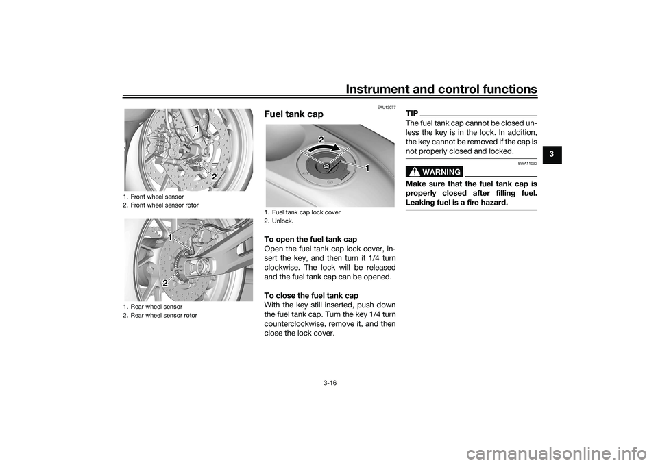
EAU13077
Fuel tank capTo open the fuel tank cap
Open the fuel tank cap lock cover, in-
sert the key, and then turn it 1/4 turn
clockwise. The lock will be released
and the fuel tank cap can be opened.
To close the fuel tank cap
With the key still inserted, push down
the fuel tank cap. Turn the key 1/4 turn
counterclockwise, remove it, and then
close the lock cover.
TIPThe fuel tank cap cannot be closed un-
less the key is in the lock. In addition,
the key cannot be removed if the cap is
not properly closed and locked.
WARNING
EWA11092
Make sure that the fuel tank cap is
properly closed after filling fuel.
Leaking fuel is a fire hazard.
1. Front wheel sensor
2. Front wheel sensor rotor
1. Rear wheel sensor
2. Rear wheel sensor rotor
1 1 12 2
1 1 1
2 2
1. Fuel tank cap lock cover
2. Unlock.
1 1 1
2 2
UBEBE0E0.book Page 16 Monday, July 5, 2021 2:26 PM
Page 32 of 100

Instrument and control functions
3-17
3
EAU13222
FuelMake sure there is sufficient gasoline in
the tank.
WARNING
EWA10882
Gasoline and gasoline vapors are
extremely flammable. To avoid fires
and explosions and to reduce the
risk of injury when refueling, follow
these instructions.1. Before refueling, turn off the en-gine and be sure that no one is sit-
ting on the vehicle. Never refuel
while smoking, or while in the vi-
cinity of sparks, open flames, or
other sources of ignition such as
the pilot lights of water heaters
and clothes dryers.
2. Do not overfill the fuel tank. When refueling, be sure to insert the
pump nozzle into the fuel tank filler
hole. Stop filling when the fuel
reaches the bottom of the filler
tube. Because fuel expands when
it heats up, heat from the engine or
the sun can cause fuel to spill out
of the fuel tank. 3. Wipe up any spilled fuel immedi-
ately. NOTICE: Immediately
wipe off spilled fuel with a clean,
dry, soft cloth, since fuel may
deteriorate painted surfaces or
plastic parts.
[ECA10072]
4. Be sure to securely close the fuel tank cap.
WARNING
EWA15152
Gasoline is poisonous and can
cause injury or death. Handle gaso-
line with care. Never siphon gasoline
by mouth. If you should swallow
some gasoline or inhale a lot of gas-
oline vapor, or get some gasoline in
your eyes, see your doctor immedi- ately. If gasoline spills on your skin,
wash with soap and water. If gaso-
line spills on your clothing, change
your clothes.
EAU86072
Your Yamaha engine was designed to
use unleaded gasoline with a research
octane number of 90 or higher. If en-
gine knocking or pinging occurs, use a
gasoline of a different brand or higher
octane rating.
1. Fuel tank filler tube
2. Maximum fuel level
2
1
Recommended fuel:
Unleaded gasoline (E10 acceptable)
Octane number (RON): 90
Fuel tank capacity: 13 L (3.4 US gal, 2.9 Imp.gal)
Fuel tank reserve:
2.5 L (0.66 US gal, 0.55 Imp.gal)
UBEBE0E0.book Page 17 Monday, July 5, 2021 2:26 PM
Page 33 of 100

Instrument and control functions
3-18
3
TIPThis mark identifies the recom-
mended fuel for this vehicle as
specified by European regulation
(EN228).
Confirm the gasoline pump nozzle
has the same fuel identification
mark.Gasohol
There are two types of gasohol: gaso-
hol containing ethanol and that con-
taining methanol. Gasohol containing
ethanol can be used if the ethanol con-
tent does not exceed 10% (E10). Gas-
ohol containing methanol is not
recommended by Yamaha because it
can cause damage to the fuel system
or vehicle performance problems.
NOTICE
ECA11401
Use only unleaded gasoline. The use
of leaded gasoline will cause severe
damage to internal engine parts,
such as the valves and piston rings,
as well as to the exhaust system.
EAU86160
Fuel tank overflow hoseThe overflow hose drains excess gaso-
line and directs it safely away from the
vehicle.
Before operating the vehicle:
Check the fuel tank overflow hose
connection.
Check the fuel tank overflow hose
for cracks or damage, and replace
it if necessary.
Make sure that the fuel tank over-
flow hose is not blocked, and
clean it if necessary.
Make sure that the fuel tank over-
flow hose is positioned as shown.
E5
E10
1. Fuel tank overflow hose
2. Clamp
1 1 1
2 2
UBEBE0E0.book Page 18 Monday, July 5, 2021 2:26 PM
Page 44 of 100

For your safety – pre-operation checks
4-1
4
EAU1559B
Inspect your vehicle each time you use it to make sure the vehicle is in safe operating condition. Always follow the inspection
and maintenance procedures and schedules described in the Owner’s Manual.
WARNING
EWA11152
Failure to inspect or maintain the vehicle properly increases the possibility of an accident or equipment damage.
Do not operate the vehicle if you find any problem. If a problem cannot be corrected by the procedures provided in
this manual, have the vehicle inspected by a Yamaha dealer.Before using this vehicle, check the following points:
ITEMCHECKS PAGE
Fuel • Check fuel level in fuel tank.
• Refuel if necessary.
• Check fuel line for leakage.
• Check fuel tank breather hose and overflow hose for obstructions, cracks or
damage, and check hose connections. 3-17, 3-18
Engine oil • Check oil level in engine.
• If necessary, add recommended oil to specified level.
• Check vehicle for oil leakage. 6-11
Coolant • Check coolant level in reservoir.
• If necessary, add recommended coolant to specified level.
• Check cooling system for leakage. 6-14
Front brake • Check operation.
• If soft or spongy, have Yamaha dealer bleed hydraulic system.
• Check brake pads for wear.
• Replace if necessary.
• Check fluid level in reservoir.
• If necessary, add specified brake fluid to specified level.
• Check hydraulic system for leakage. 6-22, 6-22
UBEBE0E0.book Page 1 Monday, July 5, 2021 2:26 PM