2022 YAMAHA GRIZZLY 700 maintenance
[x] Cancel search: maintenancePage 144 of 176

9-45
9brake pads for wear and the brake system for
leakage. If the brake fluid level suddenly goes
down, have a Yamaha dealer check the brake sys-
tem before further riding.
WARNING
EWB02721Improper maintenance can result in loss of
braking ability. Observe these precautions:
Insufficient brake fluid may allow air to enter
the brake system, reducing braking perfor-
mance.
Clean the filler cap before removing. Use
only DOT 4 brake fluid from a sealed contain-
er.
Use only the specified brake fluid; otherwise,
the rubber seals may deteriorate, causing
leakage.
Refill with the same type of brake fluid. Add-
ing a brake fluid other than DOT 4 may result
in a harmful chemical reaction.
Be careful that water does not enter the
brake fluid reservoir when refilling. Water will
significantly lower the boiling point of the flu-
id and may result in vapor lock.
EBU24294Changing the brake fluidHave a Yamaha dealer change the brake fluid at
the intervals specified in the periodic maintenance
chart. In addition, have the oil seals of the master
cylinders and calipers as well as the brake hoses
replaced at the intervals listed below or whenever
they are damaged or leaking.
Oil seals: Replace every two years.
Brake hoses: Replace every four years.
UBLT60E0.book Page 45 Tuesday, July 13, 2021 9:16 AM
Page 146 of 176

9-47
9
EBU29077Adjusting the brake pedal free playPeriodically check the brake pedal free play and
adjust if necessary.TIPAlways perform this maintenance completely in
the following order whenever adjusting the rear
brake.
Before adjusting the brake pedal free play,
check the rear brake pads for wear.
1. Remove panel G. (See page 9-10.)
2. Loosen the locknut.
3. Turn the brake pedal free play adjusting nut in
direction (a) to increase the free play, and in
direction (b) to decrease it.
4. Tighten the locknut.
5. After adjusting, there should be slight play at the brake pedal cable joint as shown. If there
is no play, repeat steps 2 to 4.
1. Brake pedal free playBrake pedal free play:1.0–6.0 mm (0.04–0.24 in)
1
1. Brake pedal free play adjusting nut
2. Locknut
UBLT60E0.book Page 47 Tuesday, July 13, 2021 9:16 AM
Page 147 of 176

9-48
9
6. Install the panel.
If the correct free play cannot be obtained, have a
Yamaha dealer adjust it.
TIPWhen adjusting the brake pedal free play:
Be sure not to step on the brake pedal.
Make sure the rear brake lever and brake pedal
do not move.
EBU24232Axle bootsThe axle boots must be checked for damage at
the intervals specified in the periodic maintenance
chart. Check the axle boots for tears or damage. If
any damage is found, have them replaced by a
Yamaha dealer.
1. Brake pedal cable joint
2. Slight play (0.1–0.5 mm [0.004–0.02 in])
1
2
1. Front axle boot (each sideF
1
1
UBLT60E0.book Page 48 Tuesday, July 13, 2021 9:16 AM
Page 150 of 176

9-51
9
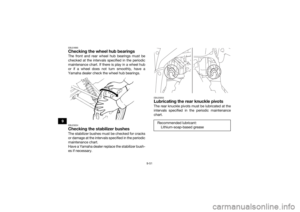
EBU24965Checking the wheel hub bearingsThe front and rear wheel hub bearings must be
checked at the intervals specified in the periodic
maintenance chart. If there is play in a wheel hub
or if a wheel does not turn smoothly, have a
Yamaha dealer check the wheel hub bearings.EBU25024Checking the stabilizer bushesThe stabilizer bushes must be checked for cracks
or damage at the intervals specified in the periodic
maintenance chart.
Have a Yamaha dealer replace the stabilizer bush-
es if necessary.
EBU25055Lubricating the rear knuckle pivotsThe rear knuckle pivots must be lubricated at the
intervals specified in the periodic maintenance
chart.Recommended lubricant: Lithium-soap-based grease
UBLT60E0.book Page 51 Tuesday, July 13, 2021 9:16 AM
Page 151 of 176

9-52
9
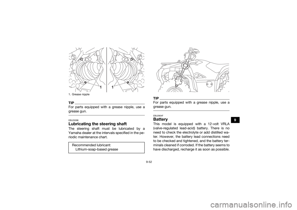
TIPFor parts equipped with a grease nipple, use a
grease gun. EBU25096Lubricating the steering shaftThe steering shaft must be lubricated by a
Yamaha dealer at the intervals specified in the pe- riodic maintenance chart.
TIPFor parts equipped with a grease nipple, use a
grease gun. EBU2904FBatteryThis model is equipped with a 12-volt VRLA
(valve-regulated lead-acid) battery. There is no
need to check the electrolyte or add distilled wa-
ter. However, the battery lead connections need
to be checked and tightened, and the battery ter-
minals cleaned if corroded. If the battery seems to
have discharged, recharge it as soon as possible.
1. Grease nippleRecommended lubricant: Lithium-soap-based grease
1
1
UBLT60E0.book Page 52 Tuesday, July 13, 2021 9:16 AM
Page 166 of 176

10-2
108. If the headlight lens has fogged up, start the
engine and turn on the headlight to help re-
move the moisture.
EBU27264StorageShort-term
Always store your ATV in a cool, dry place and, if
necessary, protect it against dust with a porous
cover. NOTICE: Storing the ATV in a poorly ven-
tilated room or covering it with a tarp while it is
still wet, will allow water and humidity to seep
in and cause rust. To prevent corrosion, avoid
damp cellars, stables (because of the presence
of ammonia) and areas where strong chemi-
cals are stored.
[ECB00722]
Long-term
Before storing your ATV for several months: 1. Make any necessary repairs and perform all outstanding maintenance.
2. Follow all the instructions in the Cleaning sec- tion of this chapter. 3. Fill up the fuel tank and add fuel stabilizer (Fu-
el Med Rx if available), and then run the en-
gine for 5 minutes to distribute the treated
fuel.
4. Perform the following steps to protect the en- gine from internal corrosion.a. Remove the spark plug cap and spark plug.
b. Pour a teaspoonful of engine oil into the spark plug bore.
c. Install the spark plug cap onto the spark plug, and then place the spark plug on the
cylinder head so that the electrodes are
grounded. (This will limit sparking during
the next step.)
d. Turn the engine over several times with the starter. (This will coat the cylinder wall
with oil.)
e. Remove the spark plug cap from the spark plug, and then install the spark plug and
the spark plug cap.
5. Lubricate all control cables and the pivoting points of all levers and pedals.
Specified amount:
7.5 ml per liter of fuel (1 oz per gallon)UBLT60E0.book Page 2 Tuesday, July 13, 2021 9:16 AM
Page 174 of 176

13-2
13
LLabel locations ............................................................... 2-1
Light switch .................................................................. 5-12
Low-range indicator light ............................................... 5-2MMain switch .................................................................... 5-1
Maintenance chart, emission control system ................ 9-3
Maintenance chart, general maintenance and lubrication .................................................................... 9-5
Model label ..................................................................... 1-1
Multi-function display .....................................................5-5NNeutral indicator light .....................................................5-2OOn-Command drive switch “4WD/LOCK” ................... 5-14
Override switch ............................................................ 5-12
Owner’s Manuals and Tool Kit ....................................... 9-2PPanels, removing and installing ................................... 9-10
Park indicator light ......................................................... 5-2
Parking ........................................................................... 7-4
Parking on a slope ......................................................... 7-5
Part locations ................................................................. 4-1RRear knuckle pivots, lubricating ................................... 9-51
Reverse indicator light ................................................... 5-2
Riding your ATV ............................................................. 8-1SSafety information .......................................................... 3-1
Seat .............................................................................. 5-21 Shock absorber assemblies, adjusting the front and
rear ............................................................................. 5-26
Spark arrester, cleaning ............................................... 9-40
Spark plug, checking ................................................... 9-18
Specifications .............................................................. 11-1
Speed limiter ................................................................ 5-16
Stabilizer bushes, checking ......................................... 9-51
Starting the engine ......................................................... 7-1
Start switch .................................................................. 5-12
Steering shaft, lubricating ............................................ 9-52
Storage ........................................................................ 10-2
Storage compartments ................................................ 5-22
TThrottle lever ........................................................ 5-16, 6-5
Throttle lever free play, adjusting ................................. 9-42
Tires ............................................................................... 6-5
Trailer hitch .................................................................. 5-28
Troubleshooting ........................................................... 9-63
Troubleshooting charts ................................................ 9-64VValve clearance ............................................................ 9-42
V-belt case drain plug .................................................. 9-41
Vehicle identification number ......................................... 1-1WWheel hub bearings, checking ..................................... 9-51
Wheel, installing ........................................................... 9-62
Wheel, removing .......................................................... 9-61
Winch ........................................................................... 5-28
Winch switch ................................................................ 5-12YYamalube ..................................................................... 9-24
UBLT60E0.book Page 2 Tuesday, July 13, 2021 9:16 AM