2022 TOYOTA TUNDRA HYBRID tire pressure
[x] Cancel search: tire pressurePage 520 of 618
5227-2. Steps to take in an emergency
Owners Manual_USA_M0C031_en
4While raising, secure the tire,
taking care that the tire goes
straight up without catching
on any surrounding part, to
prevent it from flying forward
during a collision or sudden
braking.
Tightening torque:
34.7 ft•lbf (46.6 N•m, 4.8 kgf•m)
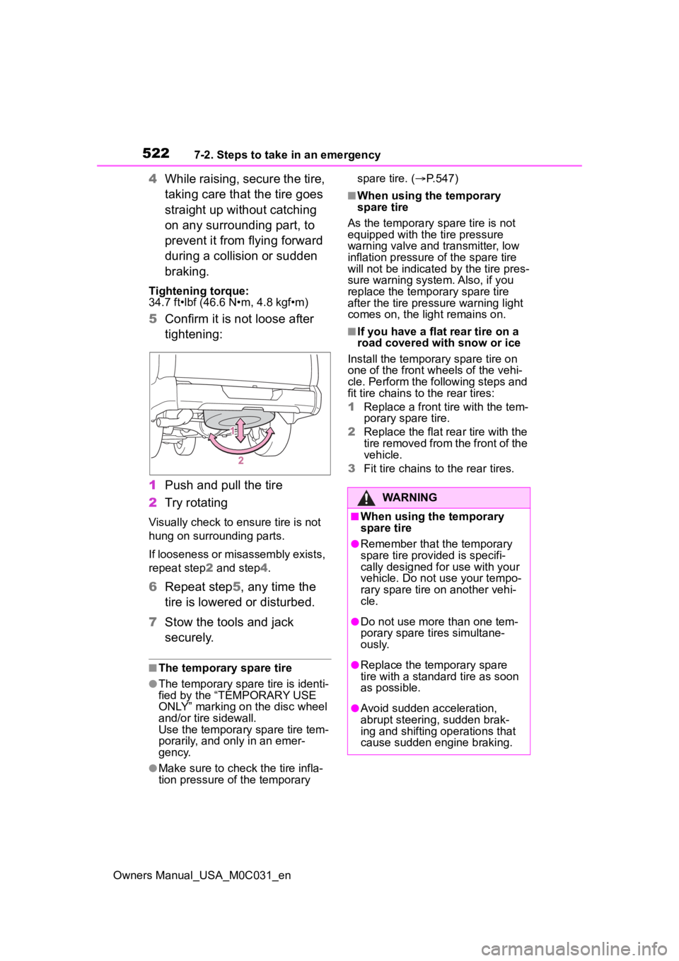
5Confirm it is not loose after
tightening:
1 Push and pull the tire
2 Try rotating
Visually check to ensure tire is not
hung on surrounding parts.
If looseness or misassembly exists,
repeat step 2 and step 4.
6 Repeat step5, any time the
tire is lowered or disturbed.
7 Stow the tools and jack
securely.
■The temporary spare tire
●The temporary spare tire is identi-
fied by the “TEMPORARY USE
ONLY” marking on the disc wheel
and/or tire sidewall.
Use the temporary spare tire tem-
porarily, and only in an emer-
gency.
●Make sure to check the tire infla-
tion pressure of the temporary spare tire. (
P.547)
■When using the temporary
spare tire
As the temporary spare tire is not
equipped with the tire pressure
warning valve and transmitter, low
inflation pressure of the spare tire
will not be indicated by the tire pres-
sure warning system. Also, if you
replace the temporary spare tire
after the tire pressure warning light
comes on, the light remains on.
■If you have a flat rear tire on a
road covered with snow or ice
Install the temporary spare tire on
one of the front w heels of the vehi-
cle. Perform the following steps and
fit tire chains to the rear tires:
1 Replace a front tire with the tem-
porary spare tire.
2 Replace the flat rear tire with the
tire removed from the front of the
vehicle.
3 Fit tire chains to the rear tires.
WARNING
■When using the temporary
spare tire
●Remember that t he temporary
spare tire provided is specifi-
cally designed for use with your
vehicle. Do not use your tempo-
rary spare tire on another vehi-
cle.
●Do not use more than one tem-
porary spare tires simultane-
ously.
●Replace the temporary spare
tire with a standa rd tire as soon
as possible.
●Avoid sudden acceleration,
abrupt steering, sudden brak-
ing and shifting operations that
cause sudden engine braking.
Page 521 of 618
5237-2. Steps to take in an emergency
Owners Manual_USA_M0C031_en
7
When trouble arises
WARNING
■When the spare tire is
attached
The vehicle speed may not be
correctly detecte d, and the follow-
ing systems may not operate cor-
rectly:
• ABS & Brake assist
• VSC
• TRAC
• AUTO LSD (if equipped)
• PCS (Pre-Collision System)
• Automatic High Beam (if equipped)
• LTA (Lane Tracing Assist)
• Dynamic radar cruise control with full-speed range
• EPS
• Trailer Sway Control
• Tire pressure warning system
• BSM (Blind Spot Monitor)
• Panoramic view monitor (if equipped)
• Multi-terrain Monitor (if equipped)
• Toyota parking assist monitor (if equipped)
• Intuitive parking assist
• PKSB (Parking Support Brake)
• Navigation system (if equipped)
Also, not only can the following
system not be utilized fully, but it
may even negatively affect the
drive-train components:
• 4WD system (if equipped)
■Speed limit when using the
temporary spare tire
Do not drive at speeds in excess
of 50 mph (80 km/h) when a tem-
porary spare tire is installed on
the vehicle.
The temporary spare tire is not
designed for driving at high
speeds. Failure to observe this
precaution may lead to an acci-
dent causing death or serious
injury.
NOTICE
■Do not drive the vehicle with
a flat tire
Do not continue driving with a flat
tire.
Driving even a short distance with
a flat tire can damage the tire and
the wheel beyond repair.
■Driving with tire chains and
the temporary spare tire
Do not fit tire chains to the tempo-
rary spare tire.
Tire chains may damage the vehi-
cle body and adversely affect driv-
ing performance.
■When stowing the flat tire
Ensure that ther e is no object
caught between t he tire and the
vehicle underbody.
■When replacing the tires
When removing or fitting the
wheels, tires or th e tire pressure
warning valve and transmitter,
contact your Toyota dealer as the
tire pressure warning valve and
transmitter may be damaged if not
handled correctly.
Page 522 of 618
5247-2. Steps to take in an emergency
Owners Manual_USA_M0C031_en
One of the following may be the
cause of the problem:
The electronic key may not be
functioning properly.
( P.527)
There may not be sufficient
fuel in the vehicle’s tank.
Refuel the vehicle.
There may be a malfunction
in the immobilizer system.
( P.81)
The hybrid system may be
malfunctioning due to an elec-
trical problem such as elec-
tronic key battery depletion or
a blown fuse. However,
depending on the type of mal-
function, an interim measure
is available to start the hybrid
system. ( P.525)
The temperature of the hybrid
battery (traction battery) may
be extremely low (below
NOTICE
■To avoid damage to the tire
pressure warning valves and
transmitters
When a tire is repaired with liquid
sealants, the tire pressure warn-
ing valve and transmitter may not
operate properly. If a liquid seal-
ant is used, contact your Toyota
dealer or other qualified service
shop as soon as possible. Make
sure to replace the tire pressure
warning valve and transmitter
when replaci ng the tire. (P.470)
If the hybrid system
will not star t
Reasons for the hybrid sys-
tem not starting vary
depending on the situation.
Check the following and
perform the appropriate
procedure:
The hybrid system will not
start even though the cor-
rect starting procedure is
being followed. ( P.195)
Page 545 of 618
5478-1. Specifications
Owners Manual_USA_M0C031_en
8
Vehicle specifications
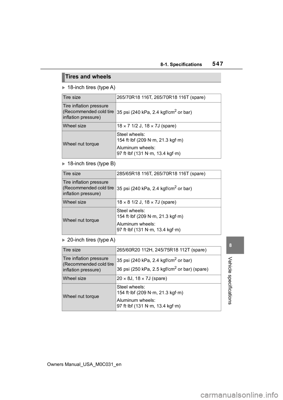
18-inch tires (type A)
18-inch tires (type B)
20-inch tires (type A)
Tires and wheels
Tire size265/70R18 116T, 265/70R18 116T (spare)
Tire inflation pressure
(Recommended cold tire
inflation pressure)
35 psi (240 kPa, 2.4 kgf/cm2 or bar)
Wheel size18 7 1/2 J, 18 7J (spare)
Wheel nut torque
Steel wheels:
154 ft·lbf (209 N·m, 21.3 kgf·m)
Aluminum wheels:
97 ft·lbf (131 N·m, 13.4 kgf·m)
Tire size285/65R18 116T, 265/70R18 116T (spare)
Tire inflation pressure
(Recommended cold tire
inflation pressure)
35 psi (240 kPa, 2.4 kgf/cm2 or bar)
Wheel size18 8 1/2 J, 18 7J (spare)
Wheel nut torque
Steel wheels:
154 ft·lbf (209 N·m, 21.3 kgf·m)
Aluminum wheels:
97 ft·lbf (131 N·m, 13.4 kgf·m)
Tire size265/60R20 112H, 245/75R18 112T (spare)
Tire inflation pressure
(Recommended cold tire
inflation pressure)35 psi (240 kPa, 2.4 kgf/cm2 or bar)
36 psi (250 kPa, 2.5 kgf/cm
2 or bar) (spare)
Wheel size20 8J, 18 7J (spare)
Wheel nut torque
Steel wheels:
154 ft·lbf (209 N·m, 21.3 kgf·m)
Aluminum wheels:
97 ft·lbf (131 N·m, 13.4 kgf·m)
Page 546 of 618
5488-1. Specifications
Owners Manual_USA_M0C031_en
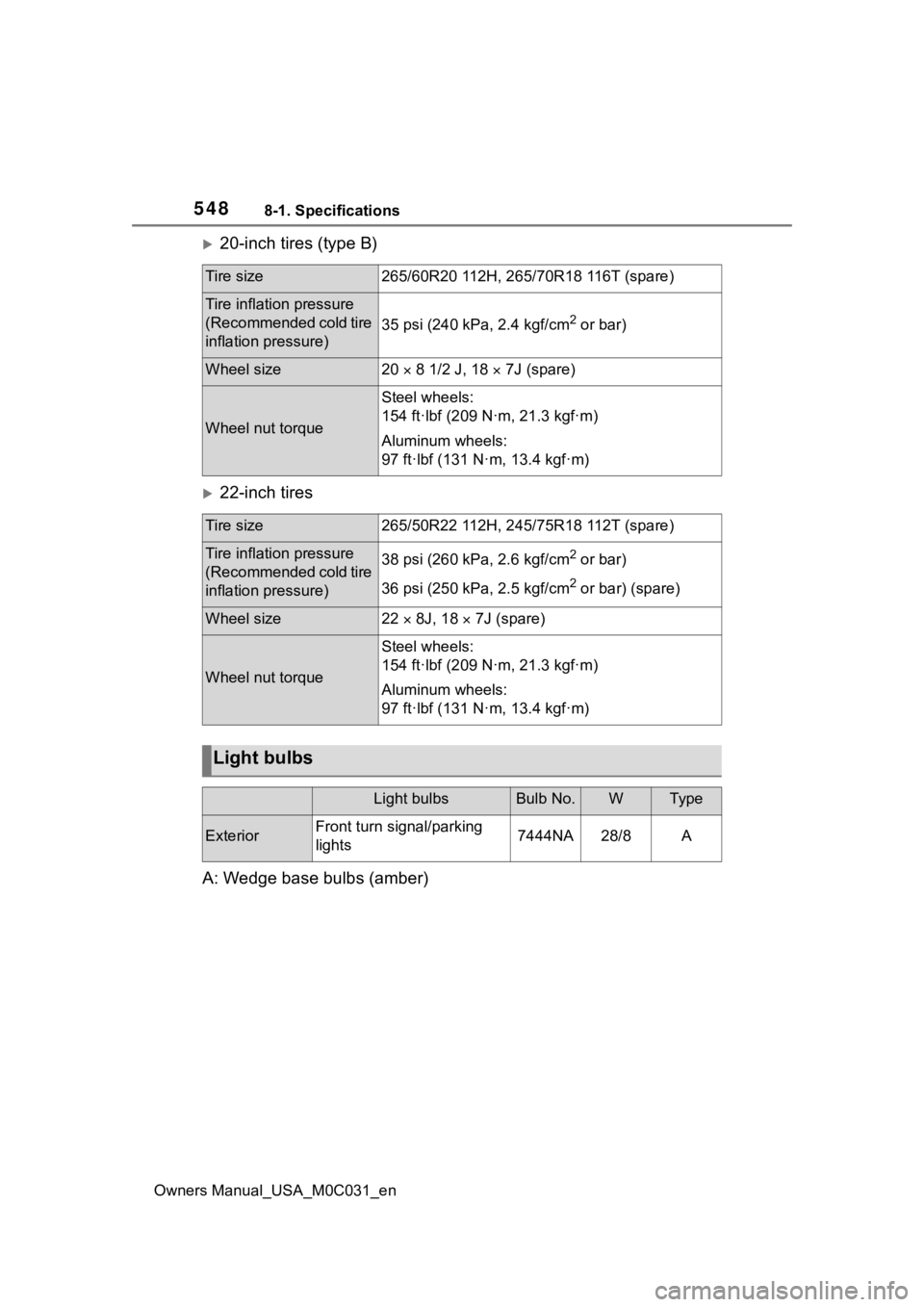
20-inch tires (type B)
22-inch tires
A: Wedge base bulbs (amber)
Tire size265/60R20 112H, 265/70R18 116T (spare)
Tire inflation pressure
(Recommended cold tire
inflation pressure)
35 psi (240 kPa, 2.4 kgf/cm2 or bar)
Wheel size20 8 1/2 J, 18 7J (spare)
Wheel nut torque
Steel wheels:
154 ft·lbf (209 N·m, 21.3 kgf·m)
Aluminum wheels:
97 ft·lbf (131 N·m, 13.4 kgf·m)
Tire size265/50R22 112H, 245/75R18 112T (spare)
Tire inflation pressure
(Recommended cold tire
inflation pressure)38 psi (260 kPa, 2.6 kgf/cm2 or bar)
36 psi (250 kPa, 2.5 kgf/cm
2 or bar) (spare)
Wheel size22 8J, 18 7J (spare)
Wheel nut torque
Steel wheels:
154 ft·lbf (209 N·m, 21.3 kgf·m)
Aluminum wheels:
97 ft·lbf (131 N·m, 13.4 kgf·m)
Light bulbs
Light bulbsBulb No.WTy pe
ExteriorFront turn signal/parking
lights7444NA28/8A
Page 549 of 618
5518-1. Specifications
Owners Manual_USA_M0C031_en
8
Vehicle specifications
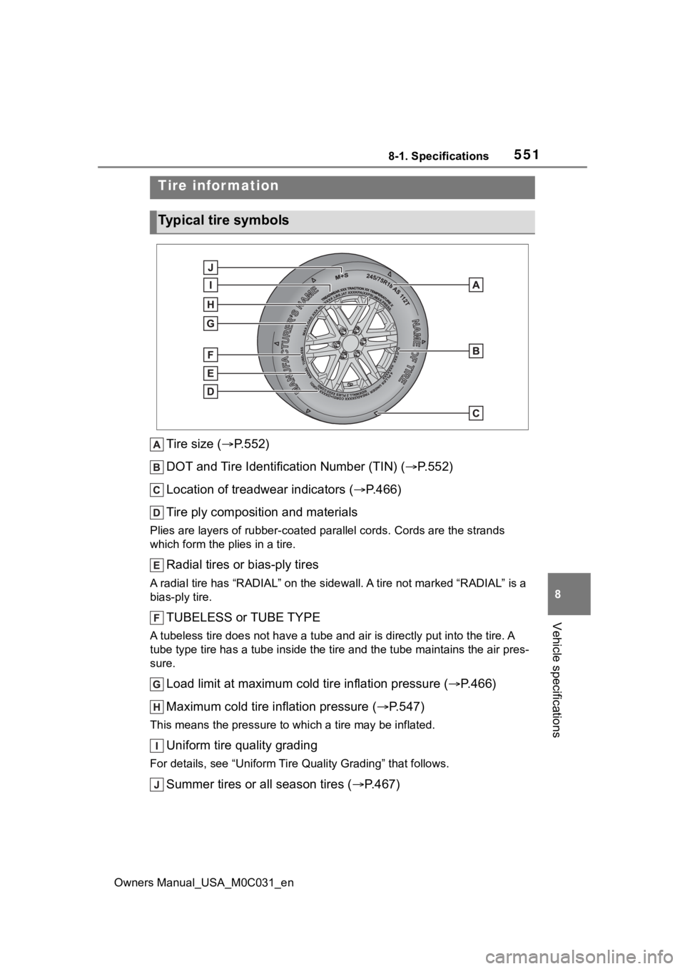
Tire size ( P.552)
DOT and Tire Identification Number (TIN) ( P.552)
Location of treadwear indicators ( P.466)
Tire ply composition and materials
Plies are layers of rubber-coat ed parallel cords. Cords are the strands
which form the pl ies in a tire.
Radial tires or bias-ply tires
A radial tire has “RADIAL” on the sidewall. A tire not marked “ RADIAL” is a
bias-ply tire.
TUBELESS or TUBE TYPE
A tubeless tire does not have a tube and air is directly put into the tire. A
tube type tire has a tube inside t he tire and the tube maintains the air pres-
sure.
Load limit at maximum cold tire inflation pressure (P.466)
Maximum cold tire inflation pressure ( P.547)
This means the pressure to w hich a tire may be inflated.
Uniform tire quality grading
For details, see “Uniform Tire Quality Grading” that follows.
Summer tires or all season tires ( P.467)
Tire information
Typical tire symbols
Page 553 of 618
5558-1. Specifications
Owners Manual_USA_M0C031_en
8
Vehicle specifications
heat buildup and possible tire fail- ure.
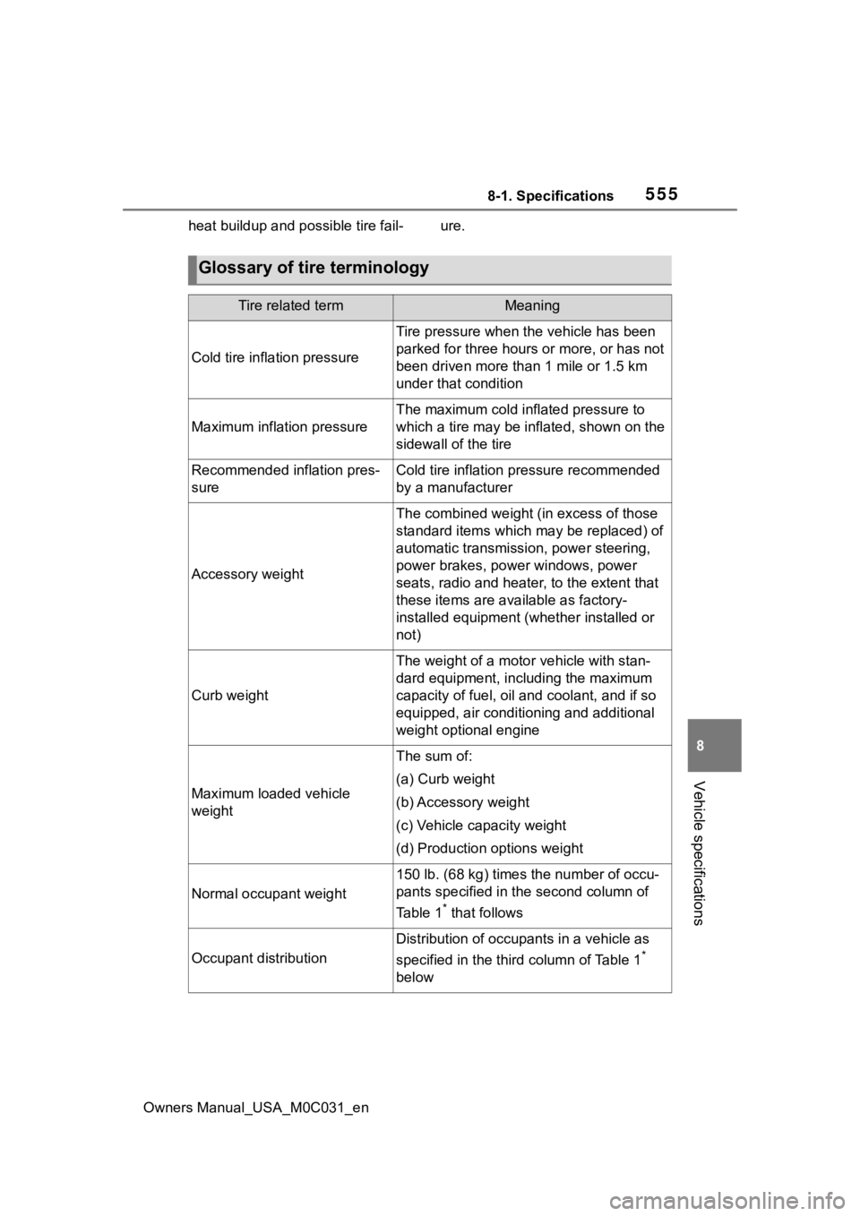
Glossary of tire terminology
Tire related termMeaning
Cold tire inflation pressure
Tire pressure when the vehicle has been
parked for three hours or more, or has not
been driven more than 1 mile or 1.5 km
under that condition
Maximum inflation pressure
The maximum cold inf lated pressure to
which a tire may be inflated, shown on the
sidewall of the tire
Recommended inflation pres-
sureCold tire inflation pressure recommended
by a manufacturer
Accessory weight
The combined weight (in excess of those
standard items which may be replaced) of
automatic transmission, power steering,
power brakes, power windows, power
seats, radio and heater, to the extent that
these items are ava ilable as factory-
installed equipment (whether installed or
not)
Curb weight
The weight of a moto r vehicle with stan-
dard equipment, including the maximum
capacity of fuel, oil and coolant, and if so
equipped, air conditioning and additional
weight optional engine
Maximum loaded vehicle
weight
The sum of:
(a) Curb weight
(b) Accessory weight
(c) Vehicle capacity weight
(d) Production options weight
Normal occupant weight
150 lb. (68 kg) times the number of occu-
pants specified in the second column of
Ta b l e 1
* that follows
Occupant distribution
Distribution of occupants in a vehicle as
specified in the third column of Table 1
*
below
Page 555 of 618
5578-1. Specifications
Owners Manual_USA_M0C031_en
8
Vehicle specifications
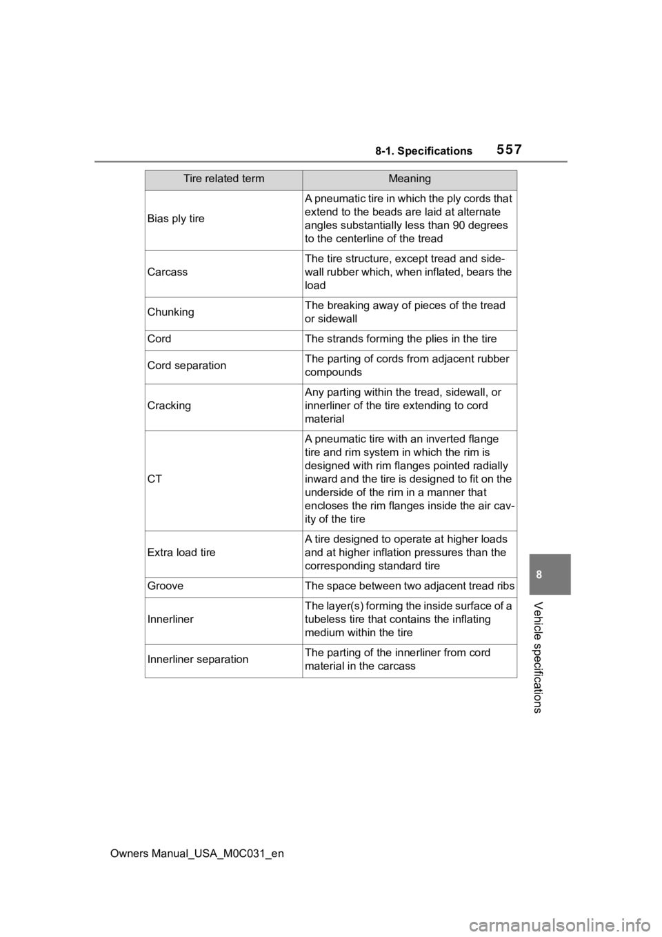
Bias ply tire
A pneumatic tire in which the ply cords that
extend to the beads are laid at alternate
angles substantially less than 90 degrees
to the centerline of the tread
Carcass
The tire structure, except tread and side-
wall rubber which, when inflated, bears the
load
ChunkingThe breaking away of pieces of the tread
or sidewall
CordThe strands forming th e plies in the tire
Cord separationThe parting of cords from adjacent rubber
compounds
Cracking
Any parting within the tread, sidewall, or
innerliner of the ti re extending to cord
material
CT
A pneumatic tire with an inverted flange
tire and rim system in which the rim is
designed with rim flanges pointed radially
inward and the tire is designed to fit on the
underside of the rim in a manner that
encloses the rim flanges inside the air cav-
ity of the tire
Extra load tire
A tire designed to operate at higher loads
and at higher inflation pressures than the
corresponding standard tire
GrooveThe space between two adjacent tread ribs
Innerliner
The layer(s) forming the inside surface of a
tubeless tire that contains the inflating
medium within the tire
Innerliner separationThe parting of the innerliner from cord
material in the carcass
Tire related termMeaning