2022 TOYOTA SIENNA HYBRID change wheel
[x] Cancel search: change wheelPage 279 of 600
2784-5. Using the driving support systems
WARNING
●Vehicle is driven in a construc-
tion zone.
●A spare tire, tire chains, etc. are
equipped.
●When the tires have been
excessively worn, or when the
tire inflation pressure is low.
●When your vehicle is towing a
trailer or during emergency tow-
ing
■Preventing LTA system mal-
functions and operations per-
formed by mistake
●Do not modify the headlights or
place stickers, etc. on the sur-
face of the lights.
●Do not modify the suspension
etc. If the suspension etc. needs
to be replaced, contact your
Toyota dealer.
●Do not install or place anything
on the hood or grille. Also, do
not install a grille guard (bull
bars, kangaroo bar, etc.).
●If your windshield needs
repairs, contact your Toyota
dealer.
■Conditions in which functions
may not operate properly
In the following situations, the
functions may not operate prop-
erly and the vehicle may depart
from its lane. Drive safely by
always paying careful attention to
your surroundings and operate
the steering wheel to correct the
path of the vehicle without relying
solely on the functions.
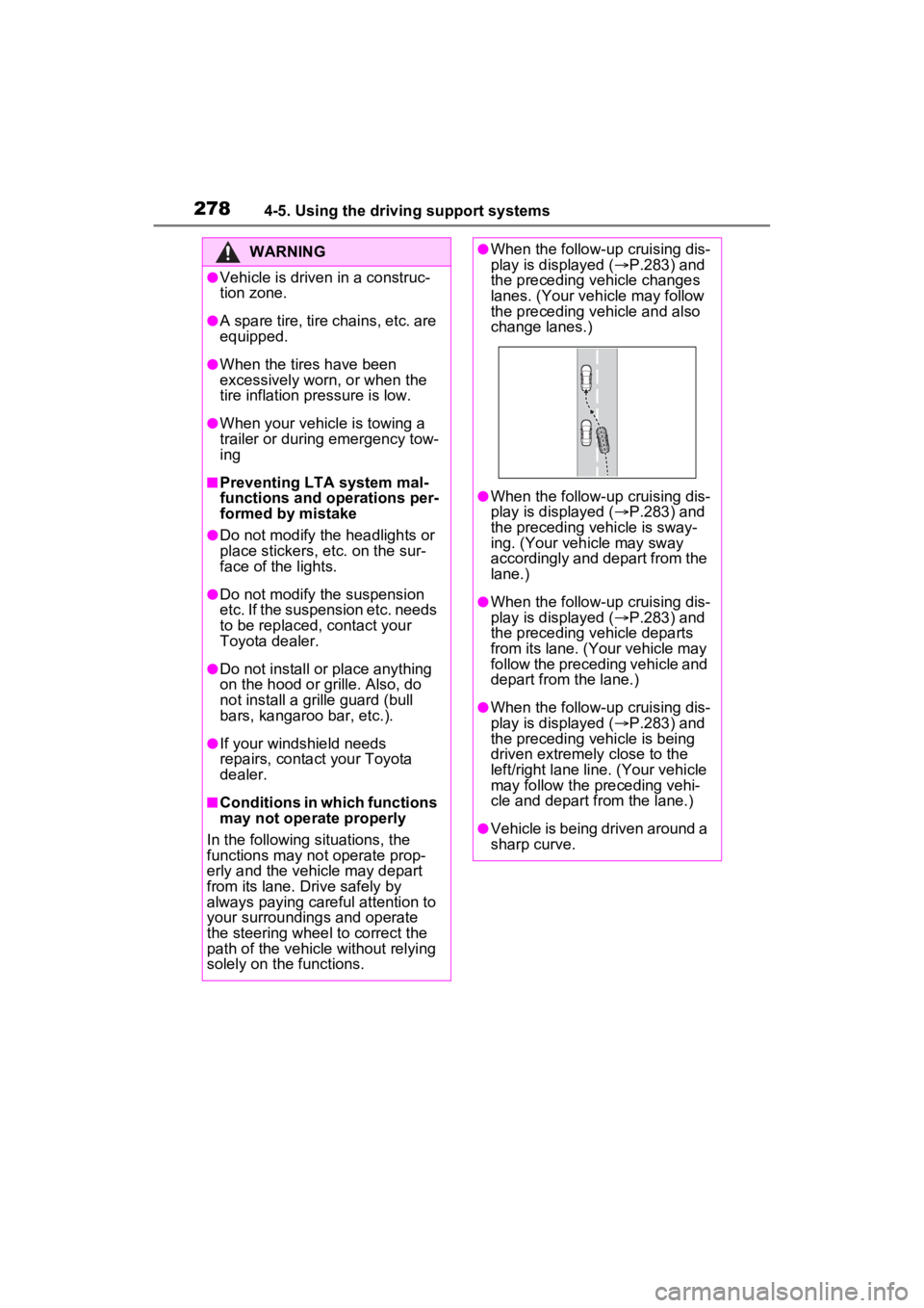
●When the follow-up cruising dis-
play is displayed ( P.283) and
the preceding vehicle changes
lanes. (Your veh icle may follow
the preceding vehicle and also
change lanes.)
●When the follow-up cruising dis-
play is displayed ( P.283) and
the preceding vehicle is sway-
ing. (Your vehicle may sway
accordingly and depart from the
lane.)
●When the follow-up cruising dis-
play is displayed ( P.283) and
the preceding vehicle departs
from its lane. (Your vehicle may
follow the preceding vehicle and
depart from the lane.)
●When the follow-up cruising dis-
play is displayed ( P.283) and
the preceding vehicle is being
driven extremely close to the
left/right lane line. (Your vehicle
may follow the preceding vehi-
cle and depart from the lane.)
●Vehicle is being driven around a
sharp curve.
Page 281 of 600
2804-5. Using the driving support systems
■Lane departure alert func-
tion
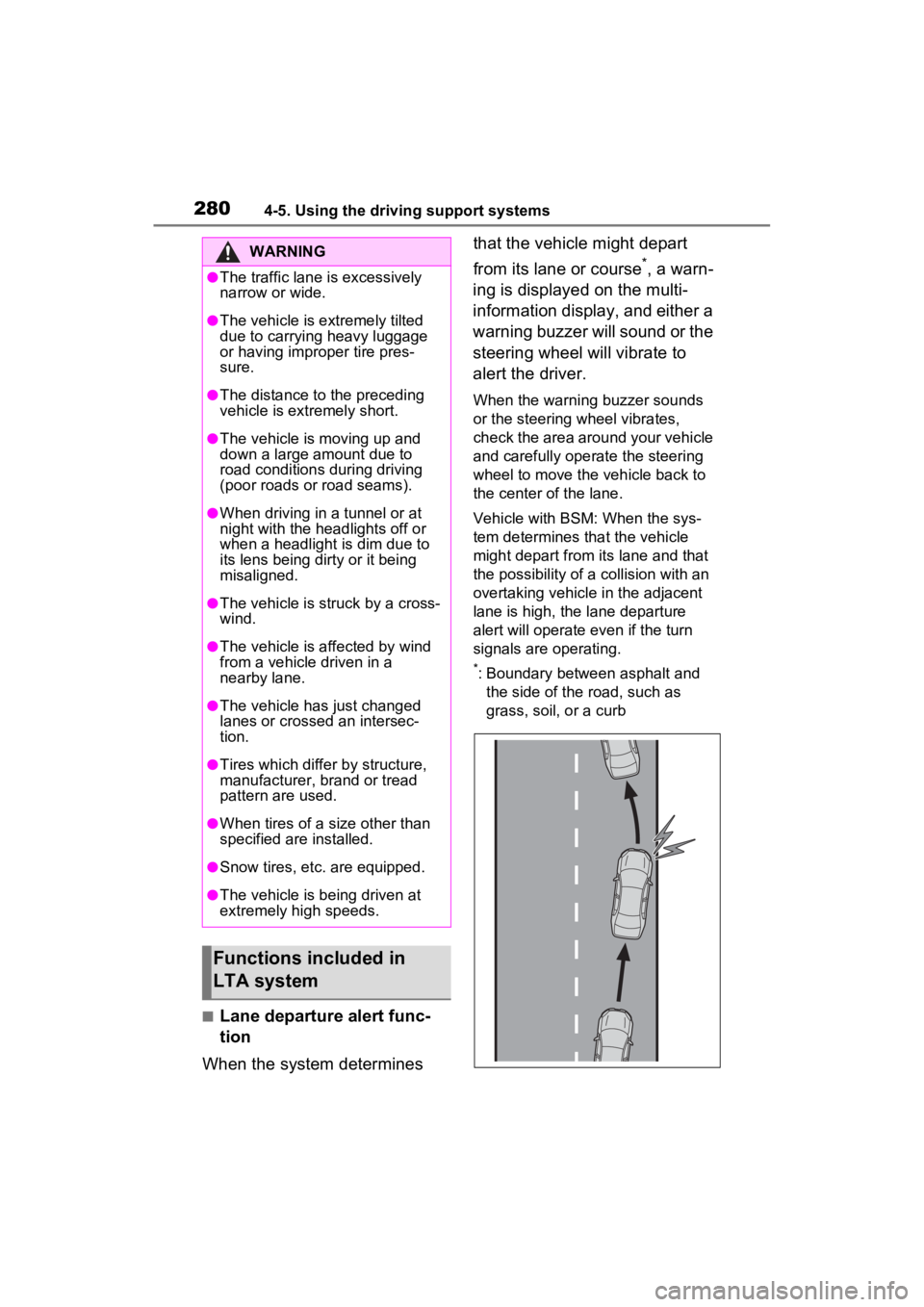
When the system determines that the vehicle might depart
from its lane or course
*, a warn-
ing is displayed on the multi-
information display, and either a
warning buzzer will sound or the
steering wheel will vibrate to
alert the driver.
When the warning buzzer sounds
or the steering wheel vibrates,
check the area around your vehicle
and carefully operate the steering
wheel to move the vehicle back to
the center of the lane.
Vehicle with BSM: When the sys-
tem determines that the vehicle
might depart from its lane and that
the possibility of a collision with an
overtaking vehicle in the adjacent
lane is high, the lane departure
alert will operate even if the turn
signals are operating.
*: Boundary between asphalt and the side of the road, such as
grass, soil, or a curb
WARNING
●The traffic lane is excessively
narrow or wide.
●The vehicle is extremely tilted
due to carrying heavy luggage
or having improper tire pres-
sure.
●The distance to the preceding
vehicle is extremely short.
●The vehicle is moving up and
down a large amount due to
road conditions during driving
(poor roads or road seams).
●When driving in a tunnel or at
night with the headlights off or
when a headlight is dim due to
its lens being dirty or it being
misaligned.
●The vehicle is struck by a cross-
wind.
●The vehicle is affected by wind
from a vehicle driven in a
nearby lane.
●The vehicle has just changed
lanes or crossed an intersec-
tion.
●Tires which differ by structure,
manufacturer, b rand or tread
pattern are used.
●When tires of a size other than
specified are installed.
●Snow tires, etc. are equipped.
●The vehicle is being driven at
extremely high speeds.
Functions included in
LTA system
Page 295 of 600

2944-5. Using the driving support systems
Example of constant speed cruising
When there are no vehicles ahead
The vehicle travels at the speed set by the driver.
Example of deceleration crui sing and follow-up cruising
When a preceding vehicle driving slower than the set speed
appears
When a vehicle is detected runni ng ahead of you, the system automatically
decelerates your vehicle. When a greater reduction in vehicle s peed is nec-
essary, the system applies the brakes (the stop lights will come on at this
time). The system will respond to changes i n the speed of the vehicle
ahead in order to maintain the ve hicle-to-vehicle distance set by the driver.
Approach warning warns you when the system cannot decelerate suffi-
ciently to prevent your vehicle from closing in on the vehicle ahead.
When the vehicle ahead of you st ops, your vehicle will also stop (vehicle is
stopped by system control). Afte r the vehicle ahead starts off, pressing the
“+RES” switch or depressing the accelerator pedal (start-off operation) will
resume follow-up cruising. If the start-off operation is not performed, system
control continues to keep your vehicle stopped.
When the turn signal lever is ope rated and your vehicle moves to an over-
taking lane while driving at 50 mph (80 km/h) or more, the vehi cle will accel-
erate to help to overt ake a passing vehicle.
The system’s identifi cation of what is an overtaking lane may be deter-
mined solely based on the location of the steering wheel in the vehicle (left
side driver position versus righ t side driver position.) If the vehicle is driven
to a region where the overtaking lane is on a different side fr om where the
vehicle is normally driven, the v ehicle may accelerate when the turn signal
lever is operated in the opposite direction to the overtaking l ane (e.g., if the
driver normally operates the vehicle in a region where the over taking lane is
to the right but then drives to a region where the overtaking l ane is to the
left, the vehicle may accelerate when the right turn signal is activated).
Example of acceleration
When there are no longer any preceding vehicles driving slower
than the set speed
The system accelerates until the set speed is reached. The system then
returns to constan t speed cruising.
1Press the cruise control main switch to activate the cruise
control.
Dynamic radar cruise control indi-
cator will come on and a message
will be displayed on
the multi-infor-
mation display. Press the switch
A
B
C
Setting the vehicle speed
(vehicle-to-vehicle dis-
tance control mode)
Page 302 of 600
3014-5. Using the driving support systems
4
Driving
correctly detect vehicles ahead, the
system may not operate properly.
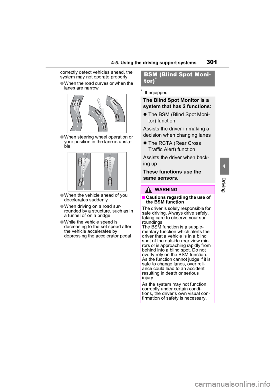
●When the road curves or when the
lanes are narrow
●When steering wheel operation or
your position in the lane is unsta-
ble
●When the vehicle ahead of you
decelerates suddenly
●When driving on a road sur-
rounded by a structure, such as in
a tunnel or on a bridge
●While the vehicle speed is
decreasing to the set speed after
the vehicle accelerates by
depressing the accelerator pedal
*: If equipped
BSM (Blind Spot Moni-
tor)*
The Blind Spot Monitor is a
system that has 2 functions:
The BSM (Blind Spot Moni-
tor) function
Assists the driver in making a
decision when changing lanes
The RCTA (Rear Cross
Traffic Alert) function
Assists the driver when back-
ing up
These functions use the
same sensors.
WARNING
■Cautions regarding the use of
the BSM function
The driver is solely responsible for
safe driving. Always drive safely,
taking care to observe your sur-
roundings.
The BSM function is a supple-
mentary function which alerts the
driver that a vehicle is in a blind
spot of the outside rear view mir-
rors or is approaching rapidly from
behind into a blin d spot. Do not
overly rely on the BSM function.
As the function cannot judge if it is
safe to change lanes, over reli-
ance could lead to an accident
resulting in dea th or serious
injury.
As the system may not function
correctly under certain condi-
tions, the driver’s own visual con-
firmation of safety is necessary.
Page 322 of 600

3214-5. Using the driving support systems
4
Driving
on
■The rear camera detection func-
tion is operational when
●The power switch is in ON.
●RCD function is on.
●The shift lever is in R.
■Setting the buzzer volume
The buzzer volume can be adjusted
on the multi-inform ation display.
( P.112)
■Muting the buzzer sound
The buzzer can be temporarily
muted by pressing “OK” of the meter
control switches w hile a suggestion
that says mute is available is shown
on the multi-info rmation display.
■If “Rear Camera Detection
Unavailable Remove the Dirt of
Rear Camera” is displayed on
the multi-information display
A rear camera lens may be dirty or
covered with snow or ice. In such
cases, if it is removed from the rear
camera lens, the system should
return to normal. ( It may be neces-
sary to drive the vehicle for some
time before the system returns to
normal. Even afte r the camera
cleaning washer operated, driving
the vehicle may al so be necessary.)
■If “Rear Camera Detection
Unavailable See Owner’s Man-
ual” is displayed on the multi-
information display
●If this message is displayed after
the 12-volt battery has been dis-
connected and reconnected, fully
turn the steering wheel to the left
and then the right on level ground.
●If this message is displayed only
when the shift lever is in R, the
rear camera lens may be dirty.
Clean the rear camera lens.
■Situations in which the system
may not operate properly
●Some pedestrians, such as the following, may no
t be detected by
the rear camera detection func-
tion, preventing the function from
operating properly:
• Pedestrians who are bending for- ward or squatting
• Pedestrians who are lying down
• Pedestrians who are running
• Pedestrians who suddenly enter the detection area
• People riding a bicycle, skate- board, or other light vehicle
• Pedestrians wearing oversized clothing such as a rain coat, long
skirt, etc., making their silhouette
obscure
• Pedestrians whose body is par- tially hidden by an object, such as
a cart or umbrella
• Pedestrians which are obscured by darkness, such as at night
●In some situations, such as the
following, pedestrians may not be
detected by the rear camera
detection function, preventing the
function from operating properly:
• When backing up in inclement weather (rain, snow, fog, etc.)
• When the rear camera is
obscured (dirt, snow, ice, etc. are
attached) or scratched
• When a very bright light, such as
the sun, or the headlights of
another vehicle, shines directly
into the rear camera
• When backing up in a place where the surrounding brightness
changes suddenly, such as at the
entrance or exi t of a garage or
underground parking lot
• When backing up in a dim envi-
ronment such as during dusk or in
an underground parking lot
• When the dedicated camera
cleaning washer is operating
• When the camera position and direction are deviated
• When a towing hook is attached
• When water droplets are flowing
on the camera lens
• When the vehicle height is
extremely changed (nose up,
nose down)
• When tire chains or an emergency
Page 361 of 600
3615-1. Using the air conditioning system and defogger
5
Interior features
*: If equipped
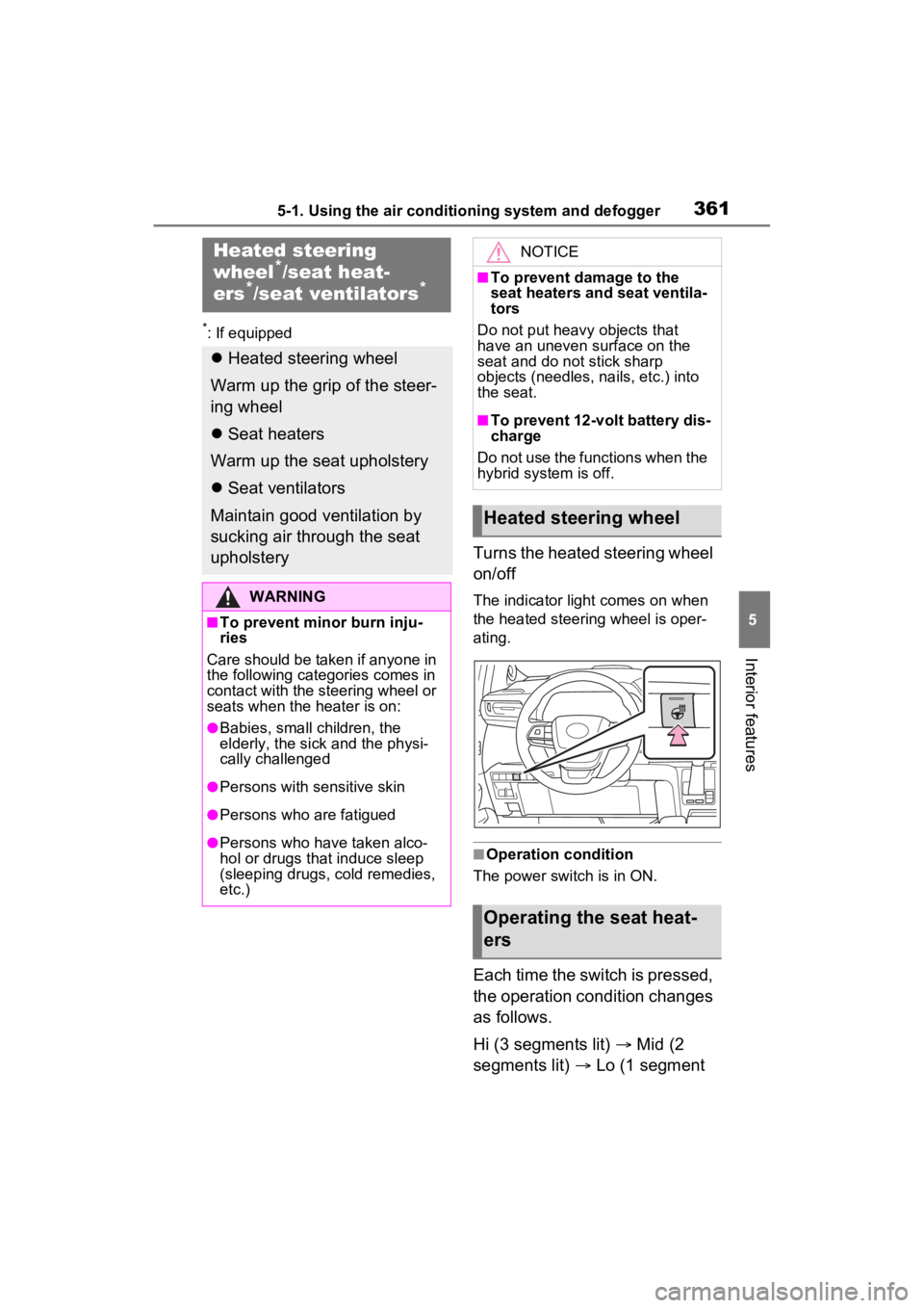
Turns the heated steering wheel
on/off
The indicator light comes on when
the heated steering wheel is oper-
ating.
■Operation condition
The power switch is in ON.
Each time the switch is pressed,
the operation condition changes
as follows.
Hi (3 segments lit) Mid (2
segments lit) Lo (1 segment
Heated steering
wheel*/seat heat-
ers*/seat ventilators*
Heated steering wheel
Warm up the grip of the steer-
ing wheel
Seat heaters
Warm up the seat upholstery
Seat ventilators
Maintain good ventilation by
sucking air through the seat
upholstery
WARNING
■To prevent minor burn inju-
ries
Care should be taken if anyone in
the following categories comes in
contact with the steering wheel or
seats when the heater is on:
●Babies, small children, the
elderly, the sick and the physi-
cally challenged
●Persons with sensitive skin
●Persons who are fatigued
●Persons who have taken alco-
hol or drugs that induce sleep
(sleeping drugs, cold remedies,
etc.)
NOTICE
■To prevent damage to the
seat heaters and seat ventila-
tors
Do not put heavy objects that
have an uneven surface on the
seat and do not stick sharp
objects (needles, nails, etc.) into
the seat.
■To prevent 12-volt battery dis-
charge
Do not use the functions when the
hybrid system is off.
Heated steering wheel
Operating the seat heat-
ers
Page 424 of 600
4246-3. Do-it-yourself maintenance
position information will not be
updated. If this accidentally occurs,
either turn the power switch to OFF
and then to ON, or initialize the sys-
tem after checking that the tire pres-
sure is properly adjusted.
Your vehicle is equipped with a
tire pressure warning system
that uses tire pressure warning
valves and transmitters to detect
low tire inflation pressure before
serious problems arise.
The tire pressure warning sys-
tem of this vehicle adopts a 2-
type warning system
When “Adjust Pressure” is
displayed (Normal Warning)
The tire pressure warning light
comes on and a buzzer sounds
when the tire inflation pressure
becomes low due to natural air
leakage or outside temperature.
(Ways of coping: P.470, 523)
When “Immediately Check
tire when Safe” is displayed
(Emergency Warning)
The tire pressure warning light
comes on and a buzzer sounds
when the tire inflation pressure
becomes low suddenly due to a
blowout. (Ways of coping: P.470,
480, 490) However, the system
may not be able to detect sudden
tire ruptures (bursting, etc.).
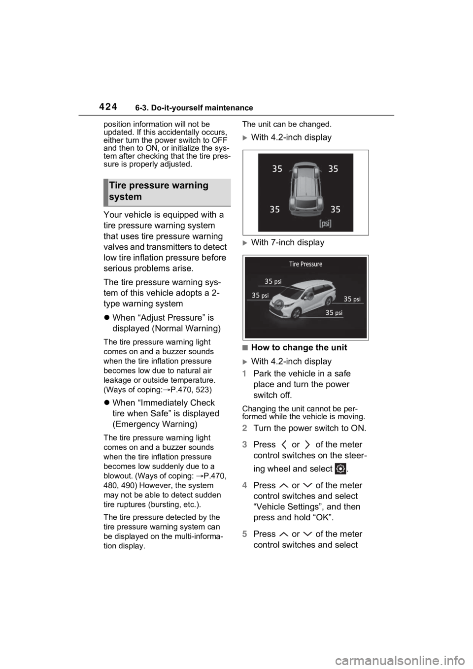
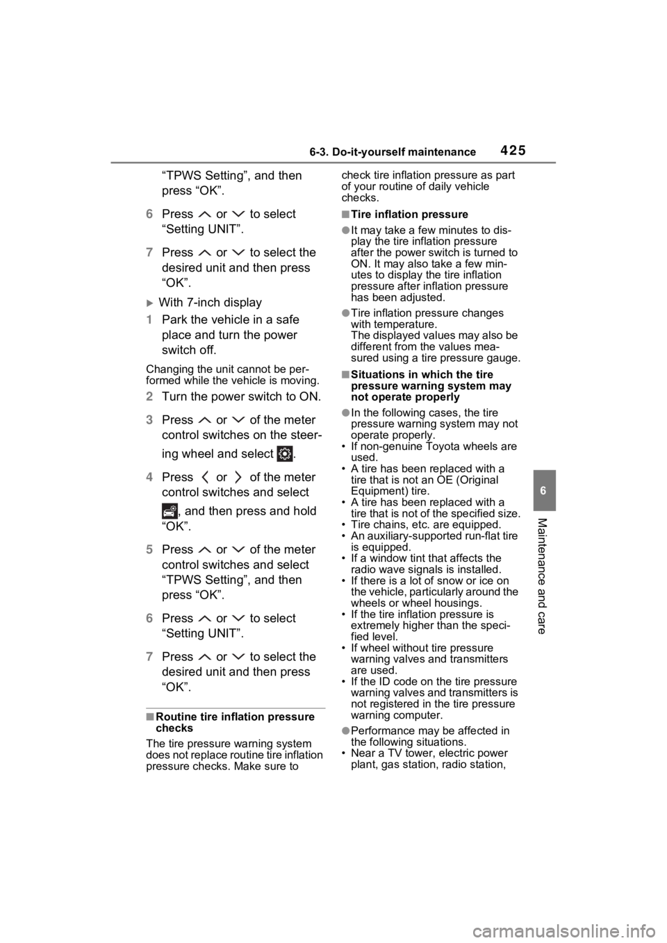
The tire pressure detected by the
tire pressure warning system can
be displayed on the multi-informa-
tion display. The unit can be changed.
With 4.2-inch display
With 7-inch display
■How to change the unit
With 4.2-inch display
1 Park the vehicle in a safe
place and turn the power
switch off.
Changing the unit cannot be per-
formed while the vehicle is moving.
2Turn the power switch to ON.
3 Press or of the meter
control switches on the steer-
ing wheel and select .
4 Press or of the meter
control switches and select
“Vehicle Settings”, and then
press and hold “OK”.
5 Press or of the meter
control switches and select
Tire pressure warning
system
35
35 35
35
Page 425 of 600
4256-3. Do-it-yourself maintenance
6
Maintenance and care
“TPWS Setting”, and then
press “OK”.
6 Press or to select
“Setting UNIT”.
7 Press or to select the
desired unit and then press
“OK”.
With 7-inch display
1 Park the vehicle in a safe
place and turn the power
switch off.
Changing the unit cannot be per-
formed while the vehicle is moving.
2Turn the power switch to ON.
3 Press or of the meter
control switches on the steer-
ing wheel and select .
4 Press or of the meter
control switches and select
, and then press and hold
“OK”.
5 Press or of the meter
control switches and select
“TPWS Setting”, and then
press “OK”.
6 Press or to select
“Setting UNIT”.
7 Press or to select the
desired unit and then press
“OK”.
■Routine tire inflation pressure
checks
The tire pressure warning system
does not replace routine tire inflation
pressure checks. Make sure to check tire inflation pressure as part
of your routine o
f daily vehicle
checks.
■Tire inflation pressure
●It may take a few minutes to dis-
play the tire inflation pressure
after the power switch is turned to
ON. It may also take a few min-
utes to display the tire inflation
pressure after infl ation pressure
has been adjusted.
●Tire inflation pressure changes
with temperature.
The displayed values may also be
different from the values mea-
sured using a tire pressure gauge.
■Situations in which the tire
pressure warning system may
not operate properly
●In the following cases, the tire
pressure warning system may not
operate properly.
• If non-genuine Toyota wheels are
used.
• A tire has been replaced with a tire that is not an OE (Original
Equipment) tire.
• A tire has been replaced with a tire that is not of the specified size.
• Tire chains, etc. are equipped.
• An auxiliary-support ed run-flat tire
is equipped.
• If a window tint that affects the radio wave signals is installed.
• If there is a lot of snow or ice on
the vehicle, particularly around the
wheels or wheel housings.
• If the tire inflation pressure is
extremely higher than the speci-
fied level.
• If wheel withou t tire pressure
warning valves and transmitters
are used.
• If the ID code on the tire pressure warning valves and transmitters is
not registered in the tire pressure
warning computer.
●Performance may be affected in
the following situations.
• Near a TV tower, electric power
plant, gas station, radio station,