Page 492 of 600

4927-2. Steps to take in an emergency
first one loosened.
1Place the wheel lock key on
top of the wheel lock nut,
turning until the wheel lock
key and wheel lock nut pat-
terns engage.
2 Place the wheel nut wrench
on the wheel lock key, and
while applying pressure on
the wheel lock key, loosen
the wheel lock nut.
■Installation
For ease of installation, the
wheel lock nut should always be
the last one tightened.
1 By hand, install a wheel lock
nut on each wheel.
2 Place the wheel lock key on
top of the wheel lock nut,
turning until the wheel lock
key and wheel lock nut pat-
terns engage.
3 Place the wheel nut wrench
on the wheel lock key, and
while applying pressure on
the wheel lock key, tighten
the wheel lock nut to the rec-
ommended torque. 1
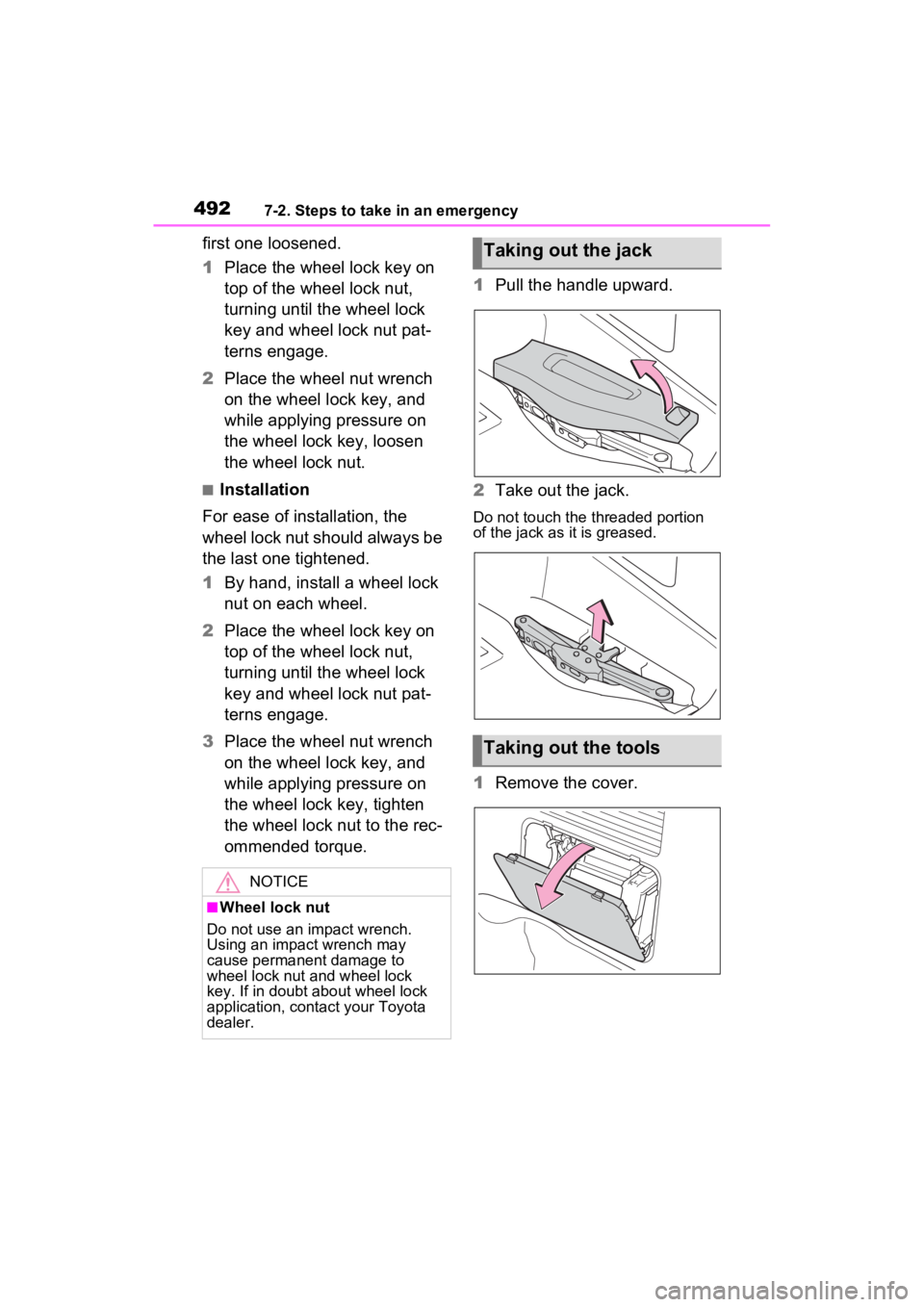
Pull the handle upward.
2 Take out the jack.
Do not touch the threaded portion
of the jack as it is greased.
1Remove the cover.
NOTICE
■Wheel lock nut
Do not use an impact wrench.
Using an impact wrench may
cause permanent damage to
wheel lock nut and wheel lock
key. If in doubt about wheel lock
application, contact your Toyota
dealer.
Taking out the jack
Taking out the tools
Page 493 of 600
4937-2. Steps to take in an emergency
7
When trouble arises
2Take out the tools
1 Remove the cover.
2 Slightly loosen the wheel
nuts (one turn). 3
Remove all the wheel nuts
and take out the spare tire.
1 Chock the tires.
Taking out the spare tire
Replacing a flat tire
Flat tireWheel chock
positions
Front left-hand
sideBehind the rear
right-hand side
tire
Front right-hand
sideBehind the rear
left-hand side
tire
Rear left-hand
sideIn front of the
front right-hand
side tire
Rear right-hand
sideIn front of the
front left-hand
side tire
Page 494 of 600
4947-2. Steps to take in an emergency
2Slightly loosen the wheel
nuts (one turn).
3 Turn the tire jack portion
by hand until the notch of the
jack is in contact with the jack
point.
After removing the jack from the
jack holder, turn the jack portion
in the opposite direction to lower
the jack, and then adjust the jack
set position.
The jack point guides are located
on the side of rocker moulding.
They indicate the jack point posi-
tions.
4Assemble the jack handle
and the wheel nut wrench as
shown in the illustration.
5 Raise the vehicle until the tire
is slightly raised off the
ground.
6 Remove all the wheel nuts
and the tire.
When resting the tire on the
ground, place the tire so that the
wheel design faces up to avoid
scratching the wheel surface.
A
A
Page 495 of 600

4957-2. Steps to take in an emergency
7
When trouble arises
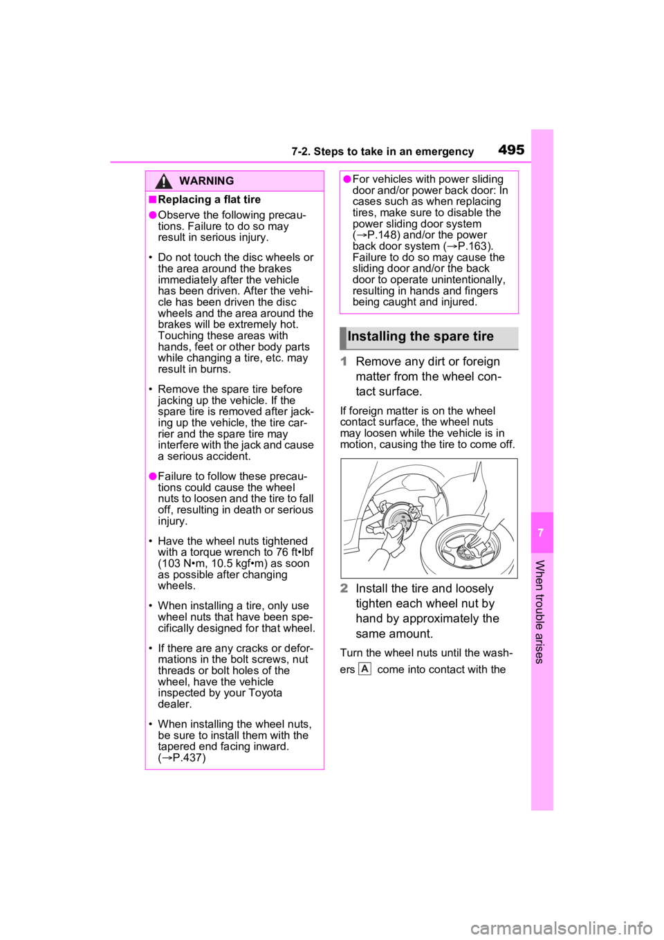
1Remove any dirt or foreign
matter from the wheel con-
tact surface.
If foreign matter is on the wheel
contact surface, the wheel nuts
may loosen while the vehicle is in
motion, causing the tire to come off.
2 Install the tire and loosely
tighten each wheel nut by
hand by approximately the
same amount.
Turn the wheel nuts until the wash-
ers come into contact with the
WARNING
■Replacing a flat tire
●Observe the following precau-
tions. Failure to do so may
result in serious injury.
• Do not touch the disc wheels or the area around the brakes
immediately after the vehicle
has been driven. After the vehi-
cle has been driven the disc
wheels and the area around the
brakes will be extremely hot.
Touching these areas with
hands, feet or other body parts
while changing a tire, etc. may
result in burns.
• Remove the spare tire before jacking up the v ehicle. If the
spare tire is removed after jack-
ing up the vehicle, the tire car-
rier and the spare tire may
interfere with the jack and cause
a serious accident.
●Failure to follow these precau-
tions could cause the wheel
nuts to loosen and the tire to fall
off, resulting in death or serious
injury.
• Have the wheel nuts tightened with a torque wrench to 76 ft•lbf
(103 N•m, 10.5 kgf•m) as soon
as possible after changing
wheels.
• When installing a tire, only use wheel nuts that have been spe-
cifically designed for that wheel.
• If there are any cracks or defor- mations in the bolt screws, nut
threads or bolt holes of the
wheel, have the vehicle
inspected by your Toyota
dealer.
• When installing the wheel nuts,
be sure to install them with the
tapered end facing inward.
( P.437)
●For vehicles with power sliding
door and/or power back door: In
cases such as wh en replacing
tires, make sure to disable the
power sliding door system
( P.148) and/or the power
back door system ( P.163).
Failure to do so may cause the
sliding door and/or the back
door to operate unintentionally,
resulting in hands and fingers
being caught and injured.
Installing the spare tire
A
Page 496 of 600

4967-2. Steps to take in an emergency
disc wheel .
3Lower the vehicle.
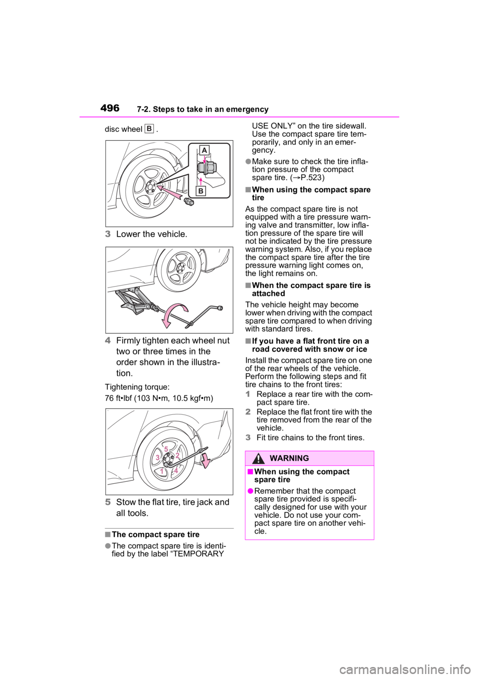
4 Firmly tighten each wheel nut
two or three times in the
order shown in the illustra-
tion.
Tightening torque:
76 ft•lbf (103 N•m, 10.5 kgf•m)
5Stow the flat tire, tire jack and
all tools.
■The compact spare tire
●The compact spare tire is identi-
fied by the label “TEMPORARY USE ONLY” on the tire sidewall.
Use the compact spare tire tem-
porarily, and only in an emer-
gency.
●Make sure to check the tire infla-
tion pressure of the compact
spare tire. (
P.523)
■When using the compact spare
tire
As the compact spare tire is not
equipped with a tire pressure warn-
ing valve and transm itter, low infla-
tion pressure of the spare tire will
not be indicated by the tire pressure
warning system. Also , if you replace
the compact spare ti re after the tire
pressure warning light comes on,
the light remains on.
■When the compact spare tire is
attached
The vehicle height may become
lower when driving with the compact
spare tire compared to when driving
with standard tires.
■If you have a flat front tire on a
road covered with snow or ice
Install the compact spare tire on one
of the rear wheels of the vehicle.
Perform the following steps and fit
tire chains to the front tires:
1 Replace a rear tire with the com-
pact spare tire.
2 Replace the flat front tire with the
tire removed from the rear of the
vehicle.
3 Fit tire chains to the front tires.
B
WARNING
■When using the compact
spare tire
●Remember that the compact
spare tire provided is specifi-
cally designed for use with your
vehicle. Do not use your com-
pact spare tire on another vehi-
cle.
Page 498 of 600
4987-2. Steps to take in an emergency
1Install the spare tire and
loosely tighten each wheel
nut by hand by approximately
the same amount.
Turn the wheel nuts until the wash-
ers come into contact with the
disc wheel .
2Firmly tighten each wheel nut
two or three times in the
order shown in the illustra-
tion.
Tightening torque: 36.9 ft•lbf (50 N•m, 5.1 kgf•m)
3
Installing the cover.
NOTICE
■When replacing the tires
When removing or fitting the
wheels, tires or the tire pressure
warning valve and transmitter,
contact your Toyota dealer as the
tire pressure warning valve and
transmitter may be damaged if not
handled correctly.
Stowing the spare tire
A
B
�:�$�5�1�,�1�*
■When stowing the compact
spare tire
Be careful not to catch fingers or
other body parts between the
compact spare tire and the body
of the vehicle.
Page 513 of 600

5137-2. Steps to take in an emergency
7
When trouble arises
1Stop the hybrid system. Set
the parking brake and shift
the shift lever to P.
2 Remove the mud, snow or
sand from around the stuck
tire.
3 Place wood, stones or some
other material to help provide
traction under the tires.
4 Restart the hybrid system
5 Shift the shift lever to D or R
and release the parking
brake. Then, while exercising
caution, depress the acceler-
ator pedal.
■When it is difficult to free the
vehicle
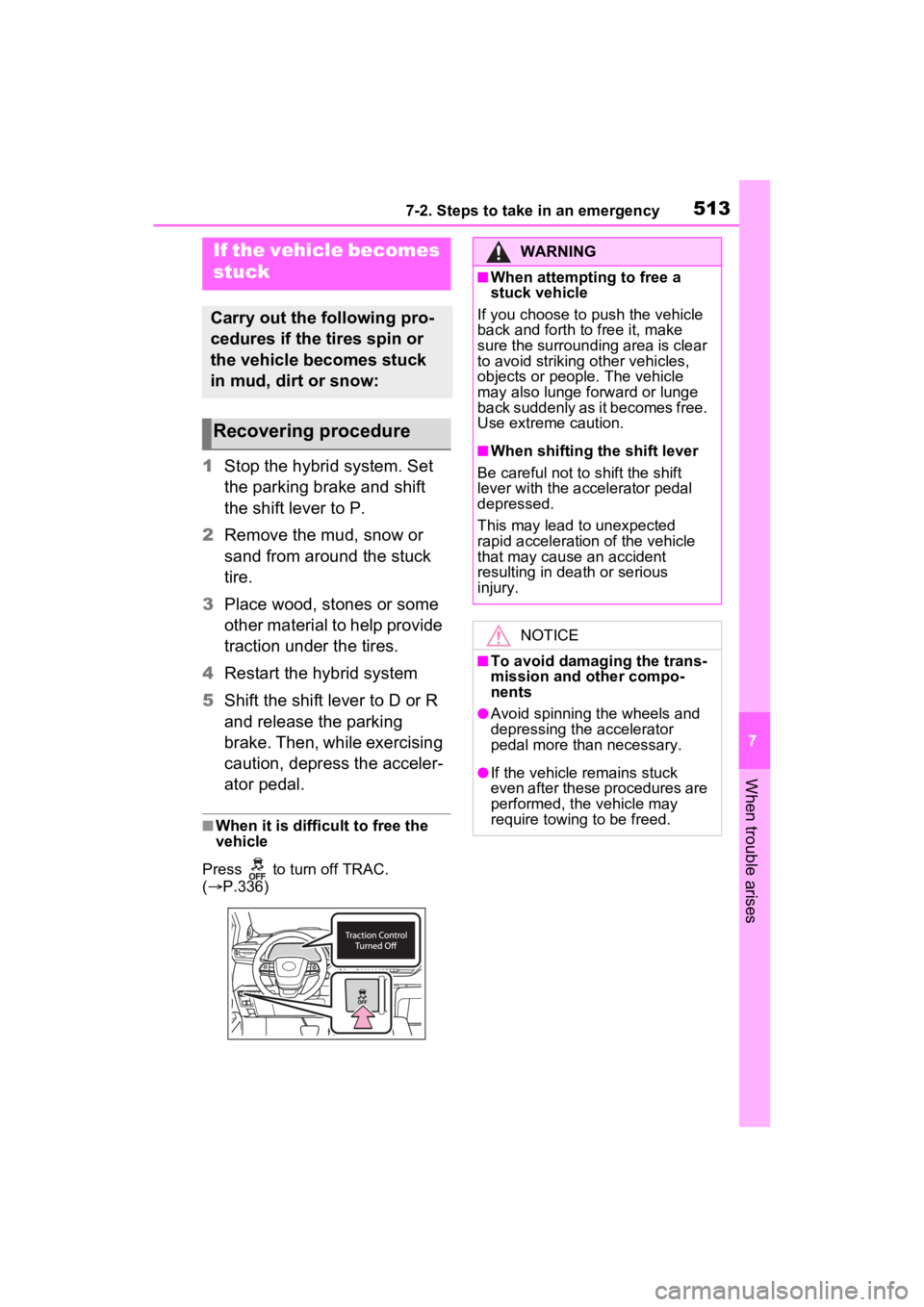
Press to turn off TRAC.
( P.336)
If the vehicle becomes
stuck
Carry out the following pro-
cedures if the tires spin or
the vehicle becomes stuck
in mud, dirt or snow:
Recovering procedure
WARNING
■When attempting to free a
stuck vehicle
If you choose to push the vehicle
back and forth to free it, make
sure the surrounding area is clear
to avoid striking other vehicles,
objects or people. The vehicle
may also lunge forward or lunge
back suddenly as it becomes free.
Use extreme caution.
■When shifting the shift lever
Be careful not to shift the shift
lever with the accelerator pedal
depressed.
This may lead to unexpected
rapid acceleration of the vehicle
that may cause an accident
resulting in dea th or serious
injury.
NOTICE
■To avoid damaging the trans-
mission and other compo-
nents
●Avoid spinning the wheels and
depressing the accelerator
pedal more than necessary.
●If the vehicle remains stuck
even after these procedures are
performed, the vehicle may
require towing to be freed.
Page 516 of 600
5168-1. Specifications
8-1.Specifications
Maintenance data (fuel, oil level, etc.)
Dimensions and weights
Overall length203.7 in. (5175 mm)*2
204.1 in. (5185 mm)*3
Overall width78.5 in. (1995 mm)
Overall height*1
68.5 in. (1740 mm)*5
69.7 in. (1770 mm)*6
70.3 in. (1785 mm)*7
Wheelbase120 in. (3060 mm)
Front tread67.7 in. (1720 mm)
Rear tread68.5 in. (1740 mm)
Vehicle capacity weight
(Occupants + luggage)
1190 lb (540 kg)*8
1235 lb (560 kg)*9
1255 lb (570 kg)*10
1375 lb (625 kg)*11
1420 lb (645 kg)*12
Trailer Weight Rating (TWR)
(Trailer weight + cargo weight)
(with towing package
*13)
3500 lb. (1585 kg)
*1:Unladen vehicle
*2:Except for AXLH40L-PNXSHA and AXLH45L-PNXSHA models*4
*3:For AXLH40L-PNXSHA and AXLH45L-PNXSHA models*4
*4:The model code is indicated on the Certification Label. For det ails, see
“Vehicle identification” below.
*5:Vehicles without roof rails
*6:Vehicles with roof rails e xcept for AXLH45L-PNXXHA model*4 with
open tray light