2022 TOYOTA PROACE CITY EV change wheel
[x] Cancel search: change wheelPage 172 of 320
172
NOTIC E
The speed will be reduced by a maximum of 16 mph (25 km/h) for versions with camera only, or by a maximum of 31 mph (50 km/h) for versions with camera and radar.
Operation
The system operates subject to the following conditions:– At reduced speed in an urban environment, when a pedestrian is detected.– At reduced speed in an urban environment, when a stationary vehicle is detected.– The vehicle's speed is between 10 km/h and 85 km/h (6 mph and 53 mph) when a moving vehicle is detected.This warning lamp flashes (for approximately 10 seconds) as soon as the function applies the vehicle’s brakes.With an automatic gearbox, in the event of automatic emergency braking bringing the
vehicle to a complete stop, keep the brake pedal depressed to prevent the vehicle from moving off again.With a manual gearbox, in the event of automatic emergency braking bringing the vehicle to a complete stop, the engine may stall.
NOTIC E
The driver can maintain control of the vehicle at any time by firmly turning the steering wheel and/or firmly depressing the accelerator pedal.
NOTIC E
The brake pedal may vibrate slightly while the function is operating.If the vehicle comes to a complete stop, automatic braking is maintained for 1 to 2 seconds.
Deactivation/Activation
By default, the system is automatically activated at every engine start.The settings are changed via the Driving / Vehicle touch screen menu.Deactivation of the system is signalled by the illumination of this warning lamp, accompanied by the display of a message.
Malfunction
In the event of a malfunction, this warning lamp comes on on the instrument panel, accompanied by the display of a message and an audible signal.Have it checked by any authorized Toyota retailer or Toyota authorized repairer, or any reliable repairer.If these warning lamps come on after the engine has been switched off and then restarted, contact any authorized Toyota retailer or Toyota authorized repairer, or any reliable repairer to have the system checked.These warning lamps light up on the instrument panel to indicate that the driver's and/or front passenger's seat belt is not fastened (depending on version). The automatic braking system is deactivated until the seat belts are fastened.
Page 173 of 320
173
Driving
6
Active Lane Departure
Warning System
WARNI NG
For more information, refer to the General recommendations on the use of driving and manoeuvring aids.
The system corrects the vehicle's trajectory by alerting the driver as soon as it detects a risk of involuntary lane departure or crossing of a verge of hard shoulder (depending on version).To do this, the system uses a camera, placed on the upper part of the windscreen, indentifying the lane markings on the ground and the side of the road (depending on version).This system is particularly useful on motorways and main roads.
Conditions for operation
– Speed of the vehicle between 70 and 180 km/h (43 and 112 mph).– Road marked with a central dividing line.– Steering wheel held in both hands.– Direction indicators not activated.– VSC system activated and operational.
WARNI NG
The system helps the driver only if there is a risk of the vehicle involuntarily wandering from the lane it is being driven in. It does not manage the safe driving distance, the speed of the vehicle or the brakes.The driver must hold the steering wheel with both hands in a way that allows control to be maintained in circumstances where the system is not able to intervene (for example, if the central dividing line marking disappears).
Operation
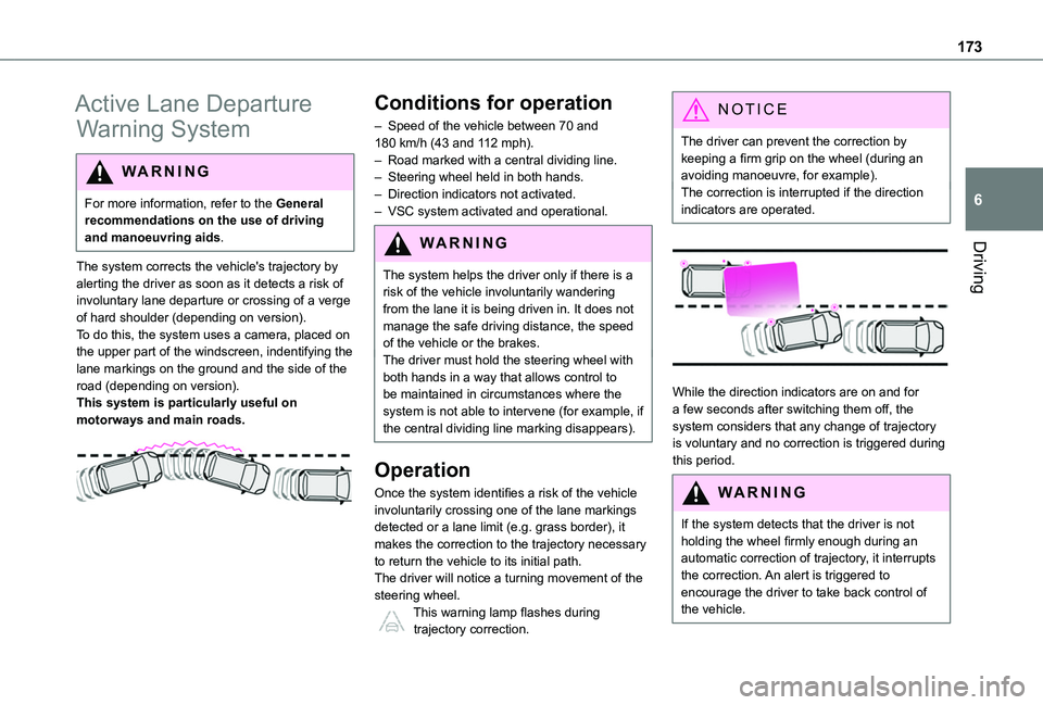
Once the system identifies a risk of the vehicle involuntarily crossing one of the lane markings detected or a lane limit (e.g. grass border), it makes the correction to the trajectory necessary to return the vehicle to its initial path.The driver will notice a turning movement of the steering wheel.This warning lamp flashes during trajectory correction.
NOTIC E
The driver can prevent the correction by keeping a firm grip on the wheel (during an avoiding manoeuvre, for example).The correction is interrupted if the direction indicators are operated.
While the direction indicators are on and for a few seconds after switching them off, the system considers that any change of trajectory is voluntary and no correction is triggered during this period.
WARNI NG
If the system detects that the driver is not holding the wheel firmly enough during an automatic correction of trajectory, it interrupts the correction. An alert is triggered to
encourage the driver to take back control of the vehicle.
Page 178 of 320
178
– In the presence of non-moving objects (parked vehicles, barriers, street lamps, road signs, etc.).– Oncoming traffic.– Driving on a winding road or a sharp corner.– When overtaking or being overtaken by a very long vehicle (lorry, bus, etc.) that is detected in the rear blind spot but is also present in the driver’s front field of vision.– When overtaking quickly.– In very heavy traffic: vehicles detected in front and behind are confused with a lorry or a stationary object.
Malfunction
If the event of malfunction, this warning lamp comes on in the instrument panel, accompanied by the display of a message.Contact a TOYOTA dealer or a qualified workshop to have the system checked.
NOTIC E
The system may suffer temporary interference in certain weather conditions (rain, hail, etc.).In particular, driving on a wet surface or moving from a dry area to a wet area can cause false alerts (for example, the presence of a fog of water droplets in the blind spot angle is interpreted as a vehicle).
In bad or wintry weather, ensure that the sensors are not covered by mud, ice or snow.Take care not to cover the warning zone in the door mirrors or the detection zones on the front and rear bumpers with adhesive labels or other objects; they may hamper correct operation of the system.
Distraction detection
WARNI NG
Refer to the General recommendations on the use of driving and manoeuvring aids.
Depending on version, the function consists of either the "Coffee Break Alert" system alone or combined with the "Driver Attention Alert" system.
WARNI NG
These systems are in no way designed to keep the driver awake or to prevent the driver from falling asleep at the wheel. It is the driver’s responsibility to stop if feeling tired.Take a break if you are feeling tired or at least
every 2 hours.
Activation/Deactivation
The settings are changed via the Driving / Vehicle touch screen menu.The state of the system is memorised when the ignition is switched off.
Coffee Break Alert
The system triggers an alert as soon as it detects that the driver has not taken a break after two hours of driving at a speed above 43 mph (70 km/h).This alert is issued via the display of a message encouraging the driver to take a break, accompanied by an audible signal.If the driver does not follow this advice, the alert is repeated hourly until the vehicle is stopped.The system resets itself if one of the following conditions is met:– With the engine running, the vehicle has been stationary for more than 15 minutes.– The ignition has been switched off for a few
minutes.– The driver's seat belt is unfastened and their door is opened.
NOTIC E
As soon as the speed of the vehicle drops below 43 mph (70 km/h), the system goes into standby.The driving time is counted again once the speed is above 43 mph (70 km/h).
Page 184 of 320
184
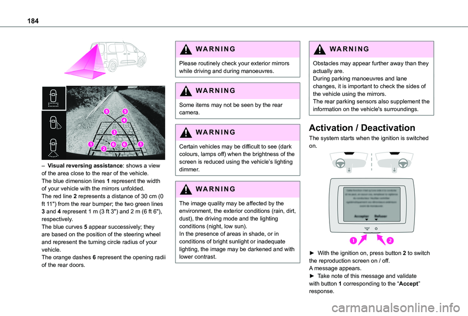
– Visual reversing assistance: shows a view of the area close to the rear of the vehicle.The blue dimension lines 1 represent the width of your vehicle with the mirrors unfolded.The red line 2 represents a distance of 30 cm (0 ft 11") from the rear bumper; the two green lines 3 and 4 represent 1 m (3 ft 3") and 2 m (6 ft 6"), respectively.The blue curves 5 appear successively; they are based on the position of the steering wheel and represent the turning circle radius of your vehicle.The orange dashes 6 represent the opening radii of the rear doors.
WARNI NG
Please routinely check your exterior mirrors while driving and during manoeuvres.
WARNI NG
Some items may not be seen by the rear camera.
WARNI NG
Certain vehicles may be difficult to see (dark colours, lamps off) when the brightness of the screen is reduced using the vehicle’s lighting dimmer.
WARNI NG
The image quality may be affected by the environment, the exterior conditions (rain, dirt, dust), the driving mode and the lighting conditions (night, low sun).In the presence of areas in shade, or in conditions of bright sunlight or inadequate lighting, the image may be darkened and with lower contrast.
WARNI NG
Obstacles may appear further away than they actually are.During parking manoeuvres and lane changes, it is important to check the sides of the vehicle using the mirrors.The rear parking sensors also supplement the information on the vehicle's surroundings.
Activation / Deactivation
The system starts when the ignition is switched on.
► With the ignition on, press button 2 to switch the reproduction screen on / off.
A message appears.► Take note of this message and validate with button 1 corresponding to the “Accept” response.
Page 187 of 320
187
Driving
6
AUTO mode
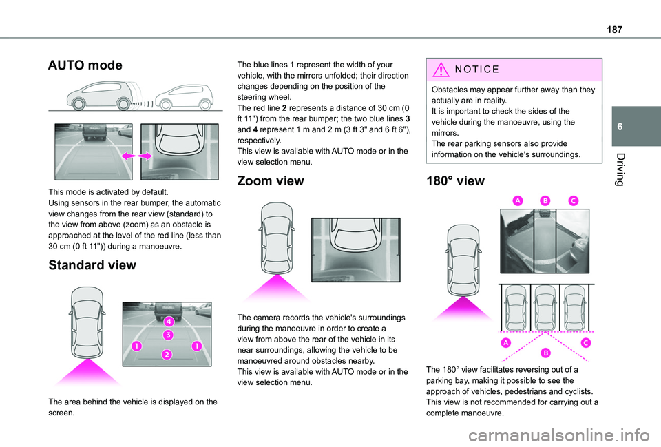
This mode is activated by default.Using sensors in the rear bumper, the automatic view changes from the rear view (standard) to the view from above (zoom) as an obstacle is approached at the level of the red line (less than 30 cm (0 ft 11")) during a manoeuvre.
Standard view
The area behind the vehicle is displayed on the
screen.
The blue lines 1 represent the width of your vehicle, with the mirrors unfolded; their direction changes depending on the position of the steering wheel.The red line 2 represents a distance of 30 cm (0 ft 11") from the rear bumper; the two blue lines 3 and 4 represent 1 m and 2 m (3 ft 3" and 6 ft 6"), respectively.This view is available with AUTO mode or in the view selection menu.
Zoom view
The camera records the vehicle's surroundings during the manoeuvre in order to create a view from above the rear of the vehicle in its near surroundings, allowing the vehicle to be manoeuvred around obstacles nearby.This view is available with AUTO mode or in the view selection menu.
NOTIC E
Obstacles may appear further away than they actually are in reality.It is important to check the sides of the vehicle during the manoeuvre, using the mirrors.The rear parking sensors also provide information on the vehicle's surroundings.
180° view
The 180° view facilitates reversing out of a parking bay, making it possible to see the approach of vehicles, pedestrians and cyclists.This view is not recommended for carrying out a
complete manoeuvre.
Page 223 of 320
223
In the event of a breakdown
8
Running out of fuel
(Diesel)
With Diesel engines, the fuel system must be primed if you run out of fuel.Before starting to prime the system, it is essential to put at least 5 litres of Diesel into the fuel tank.
NOTIC E
For more information on Refuelling and on Misfuel prevention (Diesel), refer to the corresponding section.
NOTIC E
For more information on the Engine compartment, in particular the location of these components under the bonnet, refer to the corresponding section.
With Euro 6.2/6.3 engines
► Switch on the ignition (without starting the engine).► Wait around 1 minute and switch off the ignition.► Operate the starter motor to start the engine.If the engine does not start at the first attempt,
do not keep trying, but restart the procedure.
Tool kit
► For easier access, move the seat(s) forward.
Accessing the tools
Vehicle with electric motor
With temporary puncture repair kitThe tools are located in the passenger footwell.With spare wheelThe tools are located under the right-hand front seat.To access the tools:– With non-adjustable front seat, lift the seat cushion by placing your hand between the cushion and the backrest.– With adjustable front seat, move the seat forward as far as possible.The jack is located in the passenger footwell.
Vehicle with Petrol or Diesel engine
With temporary puncture repair kitThe kit is located under the right-hand front seat.With spare wheel
The jack is located under the right-hand front seat.The tools are located under the left-hand front seat.
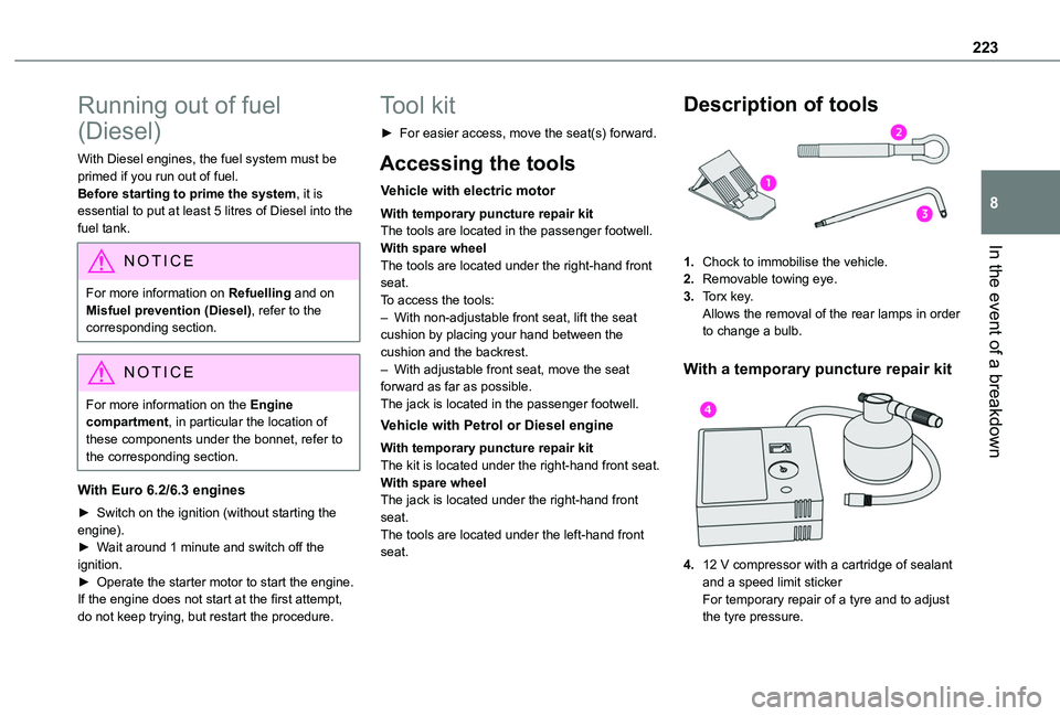
Description of tools
1.Chock to immobilise the vehicle.
2.Removable towing eye.
3.Torx key.Allows the removal of the rear lamps in order to change a bulb.
With a temporary puncture repair kit
4.12 V compressor with a cartridge of sealant and a speed limit stickerFor temporary repair of a tyre and to adjust
the tyre pressure.
Page 224 of 320
224
WARNI NG
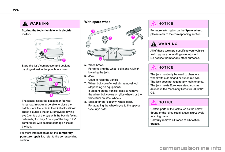
Storing the tools (vehicle with electric motor)
Store the 12 V compressor and sealant cartridge 4 inside the pouch as shown.
The space inside the passenger footwell is narrow. In order to be able to close the hatch, store the tools in their initial locations: chock 1 outside the bag, removable towing eye 2 on top of the bag with the buckle facing outwards, Torx key 3 on top of the bag, 12 V compressor with sealant cartridge 4 inside the bag.
For more information about the Temporary puncture repair kit, refer to the corresponding section.
With spare wheel
5.Wheelbrace.For removing the wheel bolts and raising/lowering the jack.
6.Jack.Used to raise the vehicle.
7.Wheel bolt cover/wheel trim removal tool (depending on equipment).If present on the vehicle, used to remove the wheel bolt covers on alloy wheels or the wheel trim on steel wheels.
8.Socket for the “security” wheel bolts.For adapting the wheelbrace to the special "security" bolts.
NOTIC E
For more information on the Spare wheel, please refer to the corresponding section.
WARNI NG
All of these tools are specific to your vehicle and may vary depending on equipment.Do not use them for any other purposes.
NOTIC E
The jack must only be used to change a wheel with a damaged or punctured tyre.The jack does not require any maintenance.The jack meets European standards, as defined in the Machinery Directive 2006/42/CE.
NOTIC E
Certain parts of the jack such as the screw thread or the joints could cause injury: avoid touching them.Carefully remove all traces of lubrication grease.
Page 227 of 320
227
In the event of a breakdown
8
Spare wheel
NOTIC E
For more information on the Tool kit, refer to the corresponding section.
► Park the vehicle, taking care to avoid obstructing traffic, and apply the parking brake.► Follow the safety instructions (hazard warning lamps, warning triangle, wearing high visibility vest, etc.) according to the legislation in force in the country where you are driving.► Switch off the ignition.
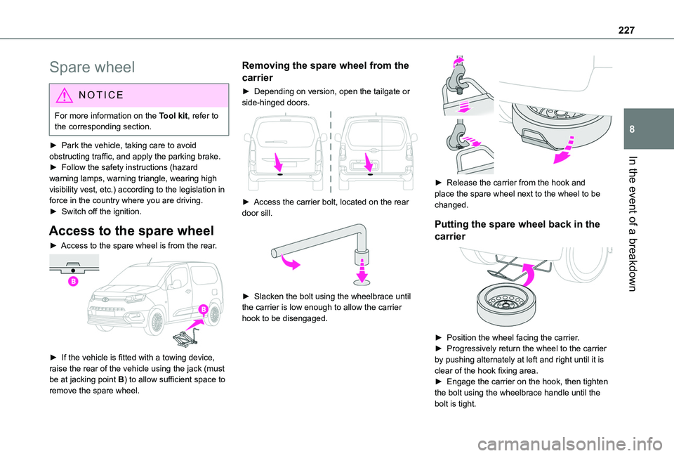
Access to the spare wheel
► Access to the spare wheel is from the rear.
► If the vehicle is fitted with a towing device, raise the rear of the vehicle using the jack (must be at jacking point B) to allow sufficient space to
remove the spare wheel.
Removing the spare wheel from the
carrier
► Depending on version, open the tailgate or side-hinged doors.
► Access the carrier bolt, located on the rear door sill.
► Slacken the bolt using the wheelbrace until the carrier is low enough to allow the carrier hook to be disengaged.
► Release the carrier from the hook and place the spare wheel next to the wheel to be changed.
Putting the spare wheel back in the
carrier
► Position the wheel facing the carrier.► Progressively return the wheel to the carrier by pushing alternately at left and right until it is clear of the hook fixing area.► Engage the carrier on the hook, then tighten the bolt using the wheelbrace handle until the bolt is tight.