2022 PEUGEOT PARTNER tool kit
[x] Cancel search: tool kitPage 5 of 324

3
Contents
Memorising speeds 150
Active Safety Brake with Collision Risk Alert and
Intelligent emergency braking assistance
150
Active lane departure warning system 153
Blind spot monitoring 156
Distraction detection 158
Parking sensors 159
Reversing Camera 161
Surround Rear Vision 162
Visiopark 1 165
Park Assist 167
7Practical informationCompatibility of fuels 172
Refuelling 172
Misfuel prevention (Diesel) 173
Charging system (Electric) 174
Charging the traction battery (Electric) 181
Energy economy mode 185
Snow chains 186
Very cold climate screen 186
Towing device 187
Overload indicator 188
Roof bars / Roof rack 189
Bonnet 190
Engine compartment 191
Checking levels 191
Checks 194
AdBlue® (BlueHDi) 195
Free-wheeling 197
Advice on care and maintenance 198
8In the event of a breakdownRunning out of fuel (Diesel) 200
Tool kit 200
Temporary puncture repair kit 202
Spare wheel 204
Changing a bulb 207
Fuses 212
12
V battery
/ Accessory battery 212
Towing 216
9Technical dataDimensions 219
Engine technical data and towed loads 225
Petrol engine 226
Diesel engine 227
Electric motor 233
Identification markings 234
10Touch screen BLUETOOTH audio systemFirst steps 235
Steering mounted controls 235
Menus 236
Radio 237
DAB (Digital Audio Broadcasting) radio 238
Media 239
Telephone 240
Settings 242
Frequently asked questions 242
11PEUGEOT Connect RadioFirst steps 245
Steering mounted controls 246
Menus 247
Applications 248
Radio 248
DAB (Digital Audio Broadcasting) radio 250
Media 250
Telephone 251
Settings 254
Frequently asked questions 256
12PEUGEOT Connect NavFirst steps 258
Steering mounted controls 259
Menus 259
Voice commands 261
Navigation 264
Connected navigation 267
Applications 269
Radio 272
DAB (Digital Audio Broadcasting) radio 273
Media 273
Telephone 275
Settings 277
Frequently asked questions 279
13Event data recorders
■
Alphabetical index
http://q-r.to/bagGl9
Access to additional videos
Page 94 of 324

92
Safety
General safety
recommendations
Do not remove the labels attached in
different places on your vehicle. They
include safety warnings as well as
identification information for the vehicle.
For all work on your vehicle, use a
qualified workshop that has the technical
information, skills and equipment required, all
of which a PEUGEOT dealer is able to
provide.
Depending on country regulations,
certain safety equipment may be
mandatory: high visibility safety vests,
warning triangles, breathalysers, spare bulbs,
spare fuses, fire extinguisher, first aid kit, mud
flaps at the rear of the vehicle, etc.
Installing electrical accessories:
– The fitting of electrical equipment or
accessories not approved by PEUGEOT
may
cause excessive current consumption and
faults and failures with the electrical system
of your vehicle. Contact a PEUGEOT dealer
for information on the range of approved
accessories.
– As a safety measure, access to the
diagnostic socket, used for the vehicle's
electronic systems, is reserved strictly for
PEUGEOT
dealers or qualified workshops,
equipped with the special tools required (risk
of malfunctions of the vehicle's electronic
systems that could cause breakdowns or
serious accidents). The Manufacturer cannot
be held responsible if this advice is not
followed.
–
Any modification or adaptation not intended
or authorised by PEUGEOT
or carried out
without meeting the technical requirements
defined by the Manufacturer will result in the
suspension of the commercial warranty.
Installation of accessory radio
communication transmitters
Before installing a radio communication
transmitter with an external aerial, you must
without fail contact a PEUGEOT dealer for
the specification of transmitters which can
be fitted (frequency, maximum power, aerial
position, specific installation requirements),
in line with the Vehicle Electromagnetic
Compatibility Directive (2004/104/EC).
Declarations of conformity for radio
equipment
The relevant certificates are available on the
http://public.servicebox.peugeot.com/APddb/
website.
Emergency or assistance
call
1. eCall (SOS)
2. ASSISTANCE
eCall (SOS)
Your vehicle may be fitted with the eCall (SOS)
system either as standard or as an option.
The eCall (SOS) system provides direct access
to the emergency services and is built directly
into the vehicle.
According to the country of sale, the eCall
(SOS)
system
corresponds to the systems PE112,
ERAGLONASS, 999, etc.
Page 133 of 324

131
Driving
6► To return to mode N, push without passing
the point of resistance.
Steering-mounted controls
(Depending on equipment)
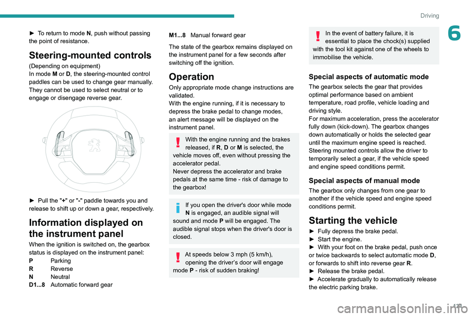
In mode M or D, the steering-mounted control
paddles can be used to change gear manually.
They cannot be used to select neutral or to
engage or disengage reverse gear.
► Pull the " +" or "-" paddle towards you and
release to shift up or down a gear, respectively.
Information displayed on
the instrument panel
When the ignition is switched on, the gearbox
status is displayed on the instrument panel:
P Parking
R Reverse
N Neutral
D1...8 Automatic forward gear
M1...8Manual forward gear
The state of the gearbox remains displayed on
the instrument panel for a few seconds after
switching off the ignition.
Operation
Only appropriate mode change instructions are
validated.
With the engine running, if it is necessary to
depress the brake pedal to change modes,
an alert message will be displayed on the
instrument panel.
With the engine running and the brakes
released, if R, D or M is selected, the
vehicle moves off, even without pressing the
accelerator pedal.
Never depress the accelerator and brake
pedals at the same time - risk of damage to
the gearbox!
If you open the driver's door while mode
N is engaged, an audible signal will
sound and mode P will be engaged. The
audible signal stops when the driver's door is
closed.
At speeds below 3 mph (5 km/h),
opening the driver ’s door will engage
mode P
- risk of sudden braking!
In the event of battery failure, it is
essential to place the chock(s) supplied
with the tool kit against one of the wheels to
immobilise the vehicle.
Special aspects of automatic mode
The gearbox selects the gear that provides
optimal performance based on ambient
temperature, road profile, vehicle loading and
driving style.
For maximum acceleration, press the accelerator
fully down (kick-down). The gearbox changes
down automatically or holds the selected gear
until the maximum engine speed is reached.
Steering mounted controls allow the driver to
temporarily select a gear, if the vehicle speed
and engine speed conditions permit.
Special aspects of manual mode
The gearbox only changes from one gear to
another if the vehicle speed and engine speed
conditions permit.
Starting the vehicle
► Fully depress the brake pedal.
► Start the engine.
►
With your foot on the brake pedal, push once
or twice backwards to select automatic mode D
,
or forwards to shift into reverse gear R.
►
Release the brake pedal.
►
Accelerate gradually to automatically release
the electric parking brake.
Page 202 of 324

200
In the event of a breakdown
Running out of fuel
(Diesel)
With Diesel engines, the fuel system must be
primed if you run out of fuel.
Before starting to prime the system, it is
essential to put at least 5 litres of Diesel into the
fuel tank.
For more information on Refuelling and
on Misfuel prevention (Diesel), refer to
the corresponding section.
For non-BlueHDi versions, the fuel system
components are located in the engine
compartment; this may be under a removable
cover.
For more information on the Engine
compartment, in particular the location
of these components under the bonnet, refer
to the corresponding section.
With 1.6 BlueHDi (Euro 6.1)
► Switch on the ignition (without starting the
engine).
►
W
ait around 6 seconds and switch off the
ignition.
►
Repeat the operation 10
times.
►
Operate the starter motor to start the engine.
If the engine does not start at the first attempt,
do not keep trying, but restart the procedure.
With 1.5 BlueHDi (Euro 6.2/6.3)
► Switch on the ignition (without starting the
engine).
►
W
ait around 1 minute and switch off the
ignition.
►
Operate the starter motor to start the engine.
If the engine does not start at the first attempt,
do not keep trying, but restart the procedure.
Non-BlueHDi engines
► Open the bonnet and then, if necessary ,
unclip the cover to access the priming pump.
► Operate the priming pump repeatedly
until resistance is felt (resistance may be
felt at the first press).
►
Operate the starter motor to start the engine
(if the engine does not start at the first attempt,
wait around 15 seconds before trying again).
►
If the engine does not start after a few
attempts, operate the priming pump again, then
the starter motor
.
►
Put the cover back in place and clip it in, then
close the bonnet.
Tool kit
► For easier access, move the seat(s) forward.
Accessing the tools
Vehicle with electric motor
With temporary puncture repair kit
The tools are located in the passenger footwell. With spare wheel
The tools are located under the right-hand front
seat.
To access the tools:
–
With non-adjustable front seat, lift the seat
cushion by placing your hand between the
cushion and the backrest.
–
With adjustable front seat, move the seat
forward as far as possible.
The jack is located in the passenger footwell.
Vehicle with Petrol or Diesel engine
With temporary puncture repair kit
The kit is located under the right-hand front seat.
With spare wheel
The jack is located under the right-hand front
seat.
The tools are located under the left-hand front
seat.
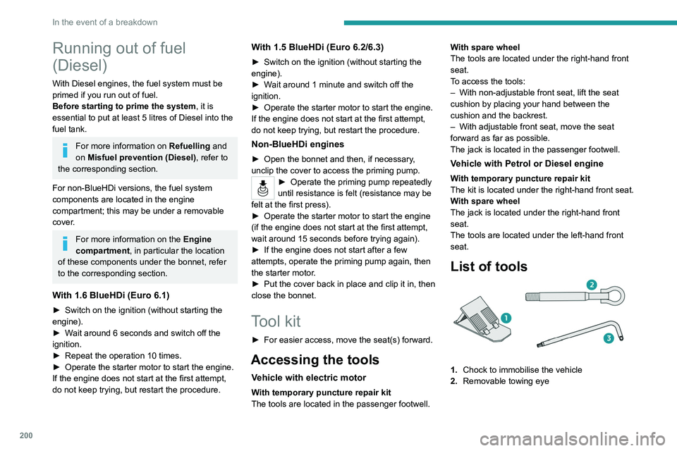
List of tools
1. Chock to immobilise the vehicle
2. Removable towing eye
Page 203 of 324

201
In the event of a breakdown
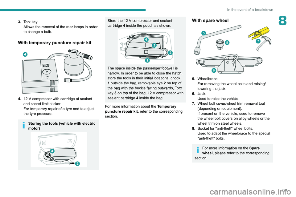
83.Torx key
Allows the removal of the rear lamps in order
to change a bulb.
With temporary puncture repair kit
4.12 V compressor with cartridge of sealant
and speed limit sticker
For temporary repair of a tyre and to adjust
the tyre pressure.
Storing the tools (vehicle with electric
motor)
Store the 12 V compressor and sealant
cartridge 4 inside the pouch as shown.
The space inside the passenger footwell is
narrow. In order to be able to close the hatch,
store the tools in their initial locations: chock
1 outside the bag, removable eye
2
on top of
the bag with the buckle facing outwards, Torx
key 3 on top of the bag, 12
V compressor with
sealant cartridge 4 inside the bag.
For more information about the Temporary
puncture repair kit, refer to the corresponding
section.
With spare wheel
5. Wheelbrace.
For removing the wheel bolts and raising/
lowering the jack.
6. Jack.
Used to raise the vehicle.
7. Wheel bolt cover/wheel trim removal tool
(depending on equipment).
If present on the vehicle, used to remove
the wheel bolt covers on alloy wheels or the
wheel trim on steel wheels.
8. Socket for "anti-theft" wheel bolts.
Used to adapt the wheelbrace to the special
"anti-theft" bolts.
For more information on the Spare
wheel, please refer to the corresponding
section.
Page 204 of 324

202
In the event of a breakdown
All of these tools are specific to your vehicle and may vary depending on
equipment.
Do not use them for any other purposes.
The jack must only be used to change a wheel with a damaged or punctured tyre.
The jack does not require any maintenance.
The jack meets European standards, as
defined in the Machinery Directive 2006/42/
EC.
Some parts of the jack such as the
screws and hinges could cause injury:
avoid touching them.
Carefully remove any traces of grease.
Temporary puncture repair kit
Scan the QR Code on page 3 to view
explanatory videos.
Made up of a compressor and a sealant
cartridge,
it allows you to carry out a temporary
repair of the tyre so that you can drive to the
nearest garage.
It is designed to repair most punctures located
on the tyre tread.
The vehicle's electric system allows the connection of the compressor to the 12 V
power supply for long enough to repair a tyre
after a puncture.
Only the 12 V socket located at the front
of the vehicle can be used to power the
compressor.
For more information on the Tool kit,
refer to the corresponding section.
Repair procedure
Do not remove any foreign body
(e.g. nail, screw) which has penetrated
the tyre.
►
Park the vehicle without obstructing traffic
and apply the parking brake.
►
Follow the safety instructions (hazard
warning lamps, warning triangle, high visibility
jacket, etc.) according to the legislation in force
in the country in which you are driving.
►
Switch the ignition off.
►
Remove the valve cap from the tyre to be
repaired, and place it in a clean place.
► Connect the pipe from the bottle of sealant to
the valve of the tyre to be repaired and tighten
firmly
.
►
Connect the pipe from the compressor to the
bottle of sealant.
►
Check that the compressor switch is in
position
"O".
►
Fully uncoil the electric cable stowed under
the compressor
.
►
Connect the compressor's electric plug to the
vehicle's 12
V socket.
► Affix the speed limit sticker .
The speed limit sticker must be affixed
inside the vehicle in the area close to the
driver, to remind them that a wheel is in
temporary use.
►
Switch the ignition on.
Page 206 of 324

204
In the event of a breakdown
Should the pressure of one or more tyres
be adjusted, it is necessary to reinitialise
the under-inflation detection system.
For more information on Tyre under-inflation
detection, refer to the corresponding section.
Spare wheel
Scan the QR Code on page 3 to view
explanatory videos.
For more information on the Tool kit,
refer to the corresponding section.
►
Park the vehicle without obstructing traffic
and apply the parking brake.
►
Follow the safety instructions (hazard
warning lamps, warning triangle, wearing high
visibility jacket, etc.) according to the legislation
in force in the country in which you are driving.
►
Switch the ignition off.
Accessing the spare wheel
► Access to the spare wheel is from the rear .
► If the vehicle is fitted with a towbar, raise
the rear of the vehicle using the jack (must be
at jacking point B) to allow sufficient space to
remove the spare wheel.
Removing the spare wheel from the
carrier
► Depending on version, open the tailgate or
side-hinged doors.
► Access the carrier bolt, located on the rear
door sill.
► Slacken the bolt using the wheelbrace until
the carrier is low enough to allow the carrier
hook to be disengaged.
► Release the carrier from the hook and
place the spare wheel next to the wheel to be
changed.
Page 213 of 324

2 11
In the event of a breakdown
8Rear lamps
For more information on Changing a bulb
and, in particular, the types of bulb, refer to the
corresponding section.
With side-hinged doors/tailgate
1. Brake lamps/sidelamps.
Type
B, P21/5W
2. Direction indicators.
Type
B, PY21W (amber)
3. Reversing lamps.
Type
B, P21W
4. Foglamps.
Type
B, P21W
► From the inside, disconnect the electrical
connector at the rear of the lamps.
► Remove the two fixing bolts using the Torx
key provided in your vehicle.
For more information on the Tool kit, please
refer to the corresponding section.
►
From the outside, pull the whole lamp unit
towards you (with side-hinged doors ) or
towards the centre of the vehicle (with tailgate
).
► Open the tabs, then pull out the lamp holder .
► Remove the faulty bulb by pressing lightly on
it while turning it a quarter turn anti-clockwise.
►
Replace the bulb.
Take care to reposition the tabs and the wiring correctly to avoid trapping the
wire.
After changing a rear direction indicator bulb, the reinitialisation time is
approximately 2 minutes or more.
Number plate lamps
Type A, W5W - 5W
With side-hinged doors