2022 PEUGEOT 3008 change wheel
[x] Cancel search: change wheelPage 159 of 292
157
Driving
6– When shifting out of reverse (the front vision
image replaces the rear vision image for 7
seconds).
–
By pressing the white arrow in the upper-left
corner of the touch screen.
If a trailer or a bicycle carrier is fitted to
the towball, the area behind the vehicle
on the view from above goes dark.
The surroundings are reconstructed by the
front camera only.
The rear vision views are similar to those for the
Visiopark 1 function.
For more information on the Visiopark
1
function, refer to the corresponding section.
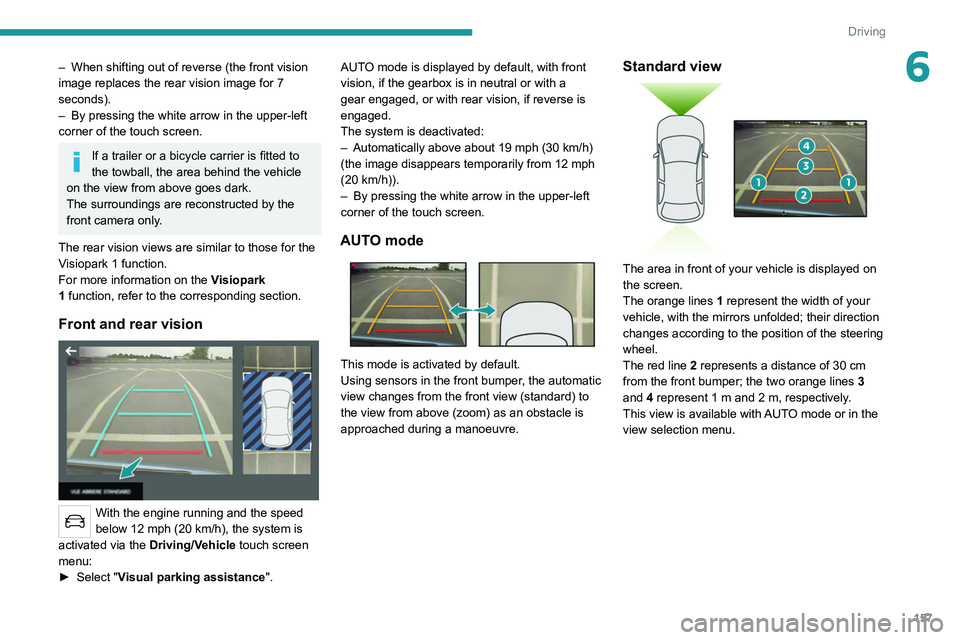
Front and rear vision
With the engine running and the speed
below 12 mph (20 km/h), the system is
activated via the Driving/Vehicle touch screen
menu:
►
Select "
Visual parking assistance". AUTO mode is displayed by default, with front
vision, if the gearbox is in neutral or with a
gear engaged, or with rear vision, if reverse is
engaged.
The system is deactivated:
–
Automatically above about 19 mph (30
km/h)
(the image disappears temporarily from 12 mph
(20 km/h)).
–
By pressing the white arrow in the upper-left
corner of the touch screen.
AUTO mode
This mode is activated by default.
Using sensors in the front bumper, the automatic
view changes from the front view (standard) to
the view from above (zoom) as an obstacle is
approached during a manoeuvre.
Standard view
The area in front of your vehicle is displayed on
the screen.
The orange lines 1 represent the width of your
vehicle, with the mirrors unfolded; their direction
changes according to the position of the steering
wheel.
The red line 2 represents a distance of 30 cm
from the front bumper; the two orange lines 3
and 4 represent 1 m and 2 m, respectively.
This view is available with AUTO mode or in the
view selection menu.
Page 178 of 292
176
Practical information
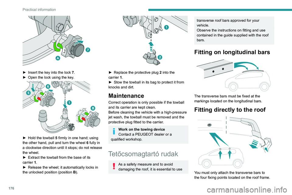
► Insert the key into the lock 7.
► Open the lock using the key .
► Hold the towball 5 firmly in one hand; using
the other hand, pull and turn the wheel 6 fully in
a clockwise direction until it stops; do not release
the wheel.
►
Extract the towball from the base of its
carrier
1.
►
Release the wheel; it automatically locks in
the unlocked position (position B
).
► Replace the protective plug 2 into the
carrier 1.
►
Stow the towball in its bag to protect it from
knocks and dirt.
Maintenance
Correct operation is only possible if the towball
and its carrier are kept clean.
Before cleaning the vehicle with a high-pressure
jet wash, the towball must be removed and the
protective plug fitted to the carrier.
Work on the towing device
Contact a PEUGEOT dealer or a
qualified workshop.
Tetőcsomagtartó rudak
As a safety measure and to avoid damaging the roof, it is essential to use
transverse roof bars approved for your
vehicle.
Observe the instructions on fitting and use
contained in the guide supplied with the roof
bars.
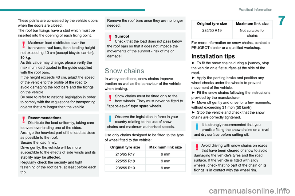
Fitting on longitudinal bars
The transverse bars must be fixed at the
markings located on the longitudinal bars.
Fitting directly to the roof
You must only attach the transverse bars to
the four fixing points located on the roof frame.
These points are concealed by the vehicle doors
when the doors are closed.
The roof bar fixings have a stud which must be
inserted into the opening of each fixing point.
Maximum load distributed over the
transverse roof bars, for a loading height
not exceeding 40 cm (except bicycle carrier):
80 kg.
As this value may change, please verify the
maximum load quoted in the guide supplied
with the roof bars.
If the height exceeds 40 cm, adapt the speed
of the vehicle to the profile of the road to
avoid damaging the roof bars and the fixings
on the vehicle.
Be sure to refer to national legislation in order
to comply with the regulations for transporting
objects that are longer than the vehicle.
Recommendations
Distribute the load uniformly, taking care
to avoid overloading one of the sides.
Arrange the heaviest part of the load as close
as possible to the roof.
Secure the load firmly.
Drive gently: the vehicle will be more
susceptible to the effects of side winds and its
stability may be affected.
Regularly check the security and tight
fastening of the roof bars, at least before each
trip.
Page 179 of 292
177
Practical information
7These points are concealed by the vehicle doors
when the doors are closed.
The roof bar fixings have a stud which must be
inserted into the opening of each fixing point.
Maximum load distributed over the
transverse roof bars, for a loading height
not exceeding 40 cm (except bicycle carrier):
80
kg.
As this value may change, please verify the
maximum load quoted in the guide supplied
with the roof bars.
If the height exceeds 40 cm, adapt the speed
of the vehicle to the profile of the road to
avoid damaging the roof bars and the fixings
on the vehicle.
Be sure to refer to national legislation in order
to comply with the regulations for transporting
objects that are longer than the vehicle.
Recommendations
Distribute the load uniformly, taking care
to avoid overloading one of the sides.
Arrange the heaviest part of the load as close
as possible to the roof.
Secure the load firmly.
Drive gently: the vehicle will be more
susceptible to the effects of side winds and its
stability may be affected.
Regularly check the security and tight
fastening of the roof bars, at least before each
trip.
Remove the roof bars once they are no longer
needed.
Sunroof
Check that the load does not pass below
the roof bars so that it does not impede the
movements of the sunroof - risk of major
damage!
Snow chains
In wintry conditions, snow chains improve
traction as well as the behaviour of the vehicle
when braking.
Snow chains must be fitted only to the
front wheels. They must never be fitted to
"space-saver" type spare wheels.
Observe the legislation in force in your
country relating to the use of snow
chains and maximum authorised speeds.
Use only chains designed to be fitted to the type
of wheel fitted to the vehicle:
Original tyre size Maximum link size 215/65 R17 9 mm
225/55 R18 9 mm
205/55 R19 9 mm
Original tyre size Maximum link size
235/50 R19 Not suitable for
chains
For more information on snow chains, contact a
PEUGEOT dealer or a qualified workshop.
Installation tips
► To fit the snow chains during a journey, stop
the vehicle on a flat surface at the side of the
road.
►
Apply the parking brake and position any
wheel chocks under the wheels to prevent
movement of the vehicle.
►
Fit the snow chains following the instructions
provided by the manufacturer
.
►
Move off gently and drive for a few moments,
without exceeding 31
mph (50 km/h).
►
Stop the vehicle and check that the snow
chains are correctly tightened.
It is strongly recommended that you
practise fitting the snow chains on a level
and dry surface before setting off.
Avoid driving with snow chains on roads that have been cleared of snow to avoid
damaging the vehicle's tyres and the road
surface. If the vehicle is fitted with alloy
wheels, check that no part of the chain or its
fixings is in contact with the wheel rim.
Page 194 of 292
192
In the event of a breakdown
The vehicle's electric system allows the connection of the compressor to the 12 V
power supply for long enough to repair a tyre
after a puncture.
Only the 12 V socket located at the front
of the vehicle can be used to power the
compressor.
For more information on the Tool kit,
refer to the corresponding section.
Tyre inflation pressures are indicated on this label.
For more information on Identification
markings, particularly this label, refer to the
corresponding section.
Should the pressure of one or more tyres
be adjusted, it is necessary to reinitialise
the under-inflation detection system.
For more information on Tyre under-inflation
detection, refer to the corresponding section.
Repair procedure
Do not remove any foreign bodies (e.g.
nail, screw) which have penetrated into
the tyre.
For more information on Towing the vehicle
and using the removable towing eye, refer to the
corresponding section.
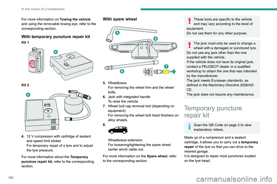
With temporary puncture repair kit
Kit 1
Kit 2
4. 12 V compressor with cartridge of sealant
and speed limit sticker
For temporary repair of a tyre and to adjust
the tyre pressure.
For more information about the Temporary
puncture repair kit, refer to the corresponding
section.
With spare wheel
5. Wheelbrace
For removing the wheel trim and the wheel
bolts.
6. Jack with integrated handle
To raise the vehicle.
7. Wheel bolt cap removal tool (depending on
equipment)
For removing the wheel bolt head finishers on
alloy wheels.
8.
Wheelbrace extension
For loosening/tightening the spare wheel
carrier winch cable nut.
For more information on the Spare wheel, refer
to the corresponding section.
These tools are specific to the vehicle and may vary according to the level of
equipment.
Do not use them for any other purpose.
The jack must only be used to change a wheel with a damaged or punctured tyre.
Do not use any jack other than the one
supplied with the vehicle.
If the vehicle does not have its original jack,
contact a PEUGEOT dealer or a qualified
workshop to obtain the one that was intended
by the manufacturer.
The jack meets European standards, as
defined in the Machinery Directive 2006/42/
CE.
The jack does not require any maintenance.
Temporary puncture repair kit
Scan the QR Code on page 3 to view
explanatory videos.
Made up of a compressor and a sealant
cartridge,
it allows you to carry out a temporary
repair of the tyre so that you can drive to the
nearest garage.
It is designed to repair most punctures located
on the tyre tread.
Page 196 of 292
194
In the event of a breakdown
With a tyre repaired using this type of kit,
do not exceed a speed of 50 mph
(80 km/h) and do not drive more than
125 miles (200 km).
Contact a PEUGEOT dealer or a qualified
workshop to have the tyre changed.
Checking/adjusting tyre
pressures
The compressor can be used, without injecting
sealant, to check and, if necessary, adjust the
tyre pressures.
► Remove the valve cap from the tyre and keep
it in a clean place.
► Uncoil the pipe stowed under the compressor.
► Screw the pipe onto the valve and tighten
firmly.
► Check that the compressor switch is in
position " O".
► Fully uncoil the electric cable stowed under
the compressor.
► Connect the compressor's electric plug to the
vehicle's 12 V socket.
► Switch the ignition on.
► Start the compressor by placing the switch at
position " I" and adjust the pressure to the value
shown on the vehicle's tyre pressure label. To
deflate: press the black button located on the
compressor pipe, near the valve connection.
If after 7 minutes the pressure of 2 bar is
not reached, the tyre is damaged;
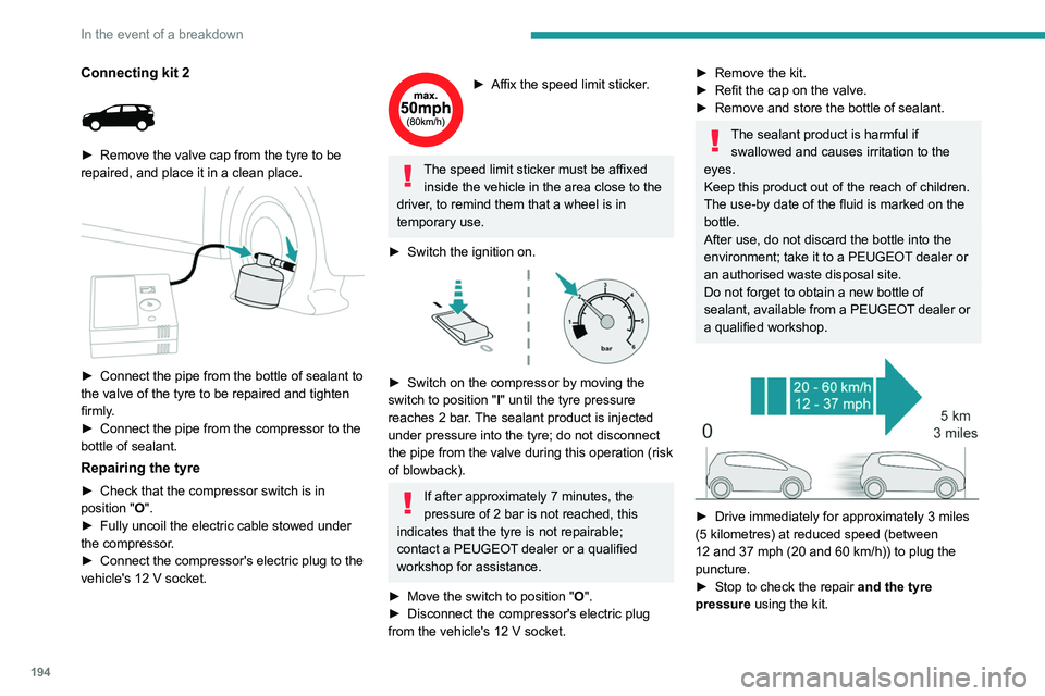
Connecting kit 2
► Remove the valve cap from the tyre to be
repaired, and place it in a clean place.
► Connect the pipe from the bottle of sealant to
the valve of the tyre to be repaired and tighten
firmly
.
►
Connect the pipe from the compressor to the
bottle of sealant.
Repairing the tyre
► Check that the compressor switch is in
position "O".
►
Fully uncoil the electric cable stowed under
the compressor
.
►
Connect the compressor's electric plug to the
vehicle's 12
V socket.
► Affix the speed limit sticker .
The speed limit sticker must be affixed
inside the vehicle in the area close to the
driver, to remind them that a wheel is in
temporary use.
►
Switch the ignition on.
► Switch on the compressor by moving the
switch to position " I
" until the tyre pressure
reaches 2 bar. The sealant product is injected
under pressure into the tyre; do not disconnect
the pipe from the valve during this operation (risk
of blowback).
If after approximately 7 minutes, the
pressure of 2 bar is not reached, this
indicates that the tyre is not repairable;
contact a PEUGEOT dealer or a qualified
workshop for assistance.
►
Move the switch to position " O
".
►
Disconnect the compressor's electric plug
from the vehicle's 12
V socket.
► Remove the kit.
► Refit the cap on the valve.
►
Remove and store the bottle of sealant.
The sealant product is harmful if swallowed and causes irritation to the
eyes.
Keep this product out of the reach of children.
The use-by date of the fluid is marked on the
bottle.
After use, do not discard the bottle into the
environment; take it to a PEUGEOT dealer or
an authorised waste disposal site.
Do not forget to obtain a new bottle of
sealant, available from a PEUGEOT dealer or
a qualified workshop.
► Drive immediately for approximately 3 miles
(5 kilometres) at reduced speed (between
12 and 37 mph (20 and 60
km/h)) to plug the
puncture.
►
Stop to check the repair
and the tyre
pressure using the kit.
Page 197 of 292
195
In the event of a breakdown
8With a tyre repaired using this type of kit,
do not exceed a speed of 50 mph
(80
km/h) and do not drive more than
125
miles (200 km).
Contact a PEUGEOT dealer or a qualified
workshop to have the tyre changed.
Checking/adjusting tyre
pressures
The compressor can be used, without injecting
sealant, to check and, if necessary, adjust the
tyre pressures.
►
Remove the valve cap from the tyre and keep
it in a clean place.
►
Uncoil
the pipe stowed under the compressor.
►
Screw the pipe onto the valve and tighten
firmly
.
►
Check that the compressor switch is in
position " O
".
►
Fully uncoil the electric cable stowed under
the compressor
.
►
Connect the compressor's electric plug to the
vehicle's 12
V socket.
►
Switch the ignition on.
►
Start the compressor by placing the switch at
position " I
" and adjust the pressure to the value
shown on the vehicle's tyre pressure label. To
deflate: press the black button located on the
compressor pipe, near the valve connection.
If after 7 minutes the pressure of 2 bar is
not reached, the tyre is damaged;
contact a PEUGEOT dealer or a qualified
workshop for assistance.
►
Once the correct pressure is reached, put the
switch in position " O
".
►
Remove the kit and stow it.
►
Refit the cap on the valve.
Spare wheel
Scan the QR Code on page 3 to view
explanatory videos.
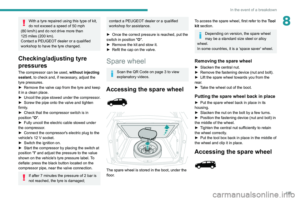
Accessing the spare wheel
The spare wheel is stored in the boot, under the
floor.
To access the spare wheel, first refer to the Tool
kit section.
Depending on version, the spare wheel
may be a standard size steel or alloy
wheel.
In some countries, it is a ‘space saver’ wheel.
Removing the spare wheel
► Slacken the central nut.
► Remove the fastening device (nut and bolt).
►
Lift the spare wheel towards you from the
rear
.
►
T
ake the wheel out of the boot.
Putting the spare wheel back in place
► Put the spare wheel back in place in its
housing.
►
Slacken the nut on the bolt by a few turns.
►
Position the fastening device (nut and bolt) in
the middle of the wheel.
►
T
ighten the central nut sufficiently to retain
the wheel correctly.
►
Put the tool box back in place in the middle of
the wheel and clip it in place.
Accessing the spare wheel
Page 200 of 292

198
In the event of a breakdown
► Remove the bolts and store them in a clean
place.
► Remove the wheel.
Fitting a wheel
Fitting a steel or "space-saver" type
spare wheel
If the vehicle is fitted with alloy wheels, the
washers A do not make contact with the steel
or "space-saver" type spare wheel. The wheel
is held in place by the conical contact surface
B of each bolt.
Removing a wheel
Wheel with wheel trim
When removing the wheel , first remove
the wheel trim by pulling at the valve aperture
using the wheelbrace.
When refitting the wheel , refit the wheel
trim, starting by placing its aperture in line
with the valve and then pushing it into place
all round its edge with the palm of your hand.
Parking the vehicle
Immobilise the vehicle where it does
not obstruct traffic: the ground must be level,
stable and non-slippery.
With a manual gearbox, engage first gear
to lock the wheels, apply the parking brake,
unless it is set to automatic mode, and switch
off the ignition.
With an automatic gearbox, select mode
P
to lock the wheels, apply the parking brake,
unless it is set to automatic mode, and switch
off the ignition.
Check that the parking brake indicator lamps
on the instrument panel are on fixed.
The occupants must get out of the vehicle
and wait where they are safe.
If necessary, place a chock under the wheel
diagonally opposite the wheel to be changed.
Never go underneath a vehicle raised using a
jack; use an axle stand.
► To remove the wheel bolt cover on each of
the bolts, use tool 7 (alloy wheels).
►
Fit security socket
2 on wheelbrace
5
to
slacken the security bolt.
►
Slacken the other bolts using the
wheelbrace
5
only.
► Place the foot of jack 6 on the ground and
ensure that it is directly below the front A or
rear
B jacking point on the underbody, whichever
is closest to the wheel to be changed.
► Extend jack 6 until its head comes into
contact with jacking point A or B; contact area A
or B on the vehicle must be properly inserted
into the central part of the head of the jack.
►
Raise the vehicle until there is sufficient
space between the wheel and the ground to
easily admit the spare (not punctured) wheel.
Ensure that the jack is stable. If the
ground is slippery or loose, the jack may
slip or collapse - risk of injury!
Take care to position the jack strictly at
one of the jacking points
A
or B under the
vehicle, ensuring that the head of the jack is
centred under the contact area on the vehicle.
Otherwise, there is a risk of damage to the
vehicle and/or of the jack collapsing - risk of
injury!
Page 226 of 292
224
PEUGEOT Connect Radio
Telephone (long press): reject an incoming call,
end call; when no call is in progress, access
telephone menu.
Radio (rotate): automatic search for the
previous/next station.
Media (rotate): previous/next track, move in a
list.
Short press: confirm a selection; if nothing
selected, access to presets.
Radio: display the list of stations.
Media: display the list of tracks.
Radio (press and hold): update the list of
stations received.
Menus
Applications
Access configurable equipment.
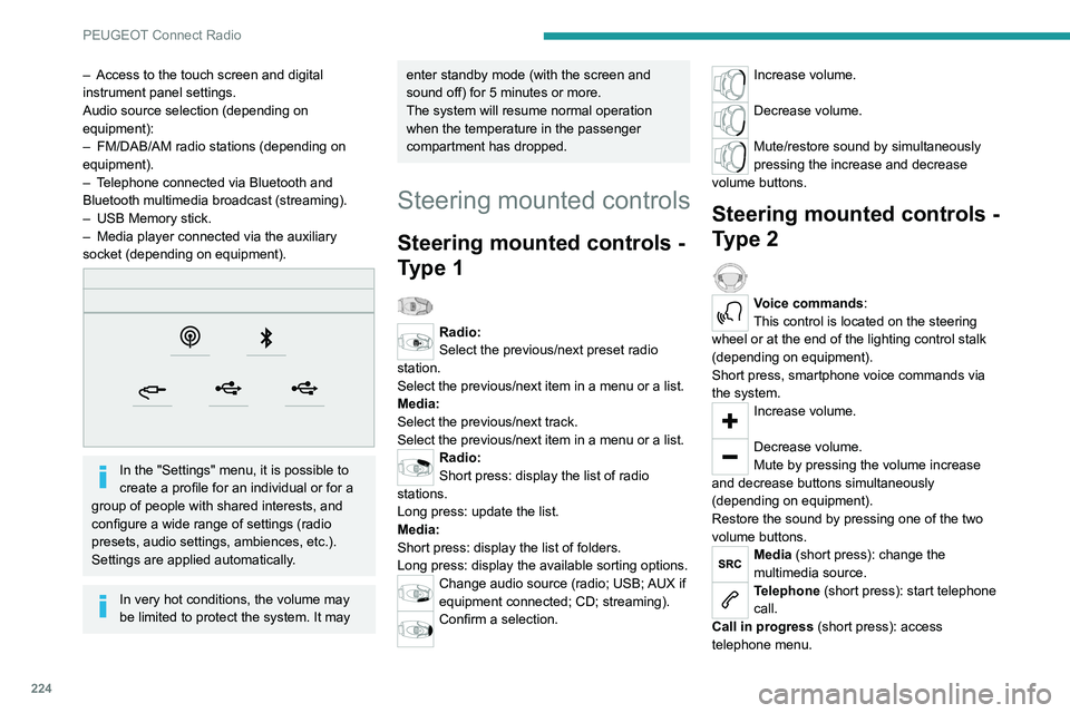
– Access to the touch screen and digital
instrument panel settings.
Audio source selection (depending on
equipment):
–
FM/DAB/AM radio stations (depending on
equipment).
–
T
elephone connected via Bluetooth and
Bluetooth multimedia broadcast (streaming).
–
USB Memory stick.
–
Media player connected via the auxiliary
socket (depending on equipment).
In the "Settings" menu, it is possible to
create a profile for an individual or for a
group of people with shared interests, and
configure a wide range of settings (radio
presets, audio settings, ambiences, etc.).
Settings are applied automatically.
In very hot conditions, the volume may
be limited to protect the system. It may
enter standby mode (with the screen and
sound off) for 5 minutes or more.
The system will resume normal operation
when the temperature in the passenger
compartment has dropped.
Steering mounted controls
Steering mounted controls -
Type 1
Radio:
Select the previous/next preset radio
station.
Select the previous/next item in a menu or a list.
Media:
Select the previous/next track.
Select the previous/next item in a menu or a list.
Radio:
Short press: display the list of radio
stations.
Long press: update the list.
Media:
Short press: display the list of folders.
Long press: display the available sorting options.
Change audio source (radio; USB; AUX if
equipment connected; CD; streaming).
Confirm a selection.
Increase volume.
Decrease volume.
Mute/restore sound by simultaneously
pressing the increase and decrease
volume buttons.
Steering mounted controls -
Type 2
Voice commands:
This control is located on the steering
wheel or at the end of the lighting control stalk
(depending on equipment).
Short press, smartphone voice commands via
the system.
Increase volume.
Decrease volume.
Mute by pressing the volume increase
and decrease buttons simultaneously
(depending on equipment).
Restore the sound by pressing one of the two
volume buttons.
Media (short press): change the
multimedia source.
Telephone (short press): start telephone
call.
Call in progress (short press): access
telephone menu.