2022 NISSAN TITAN spare wheel
[x] Cancel search: spare wheelPage 461 of 635
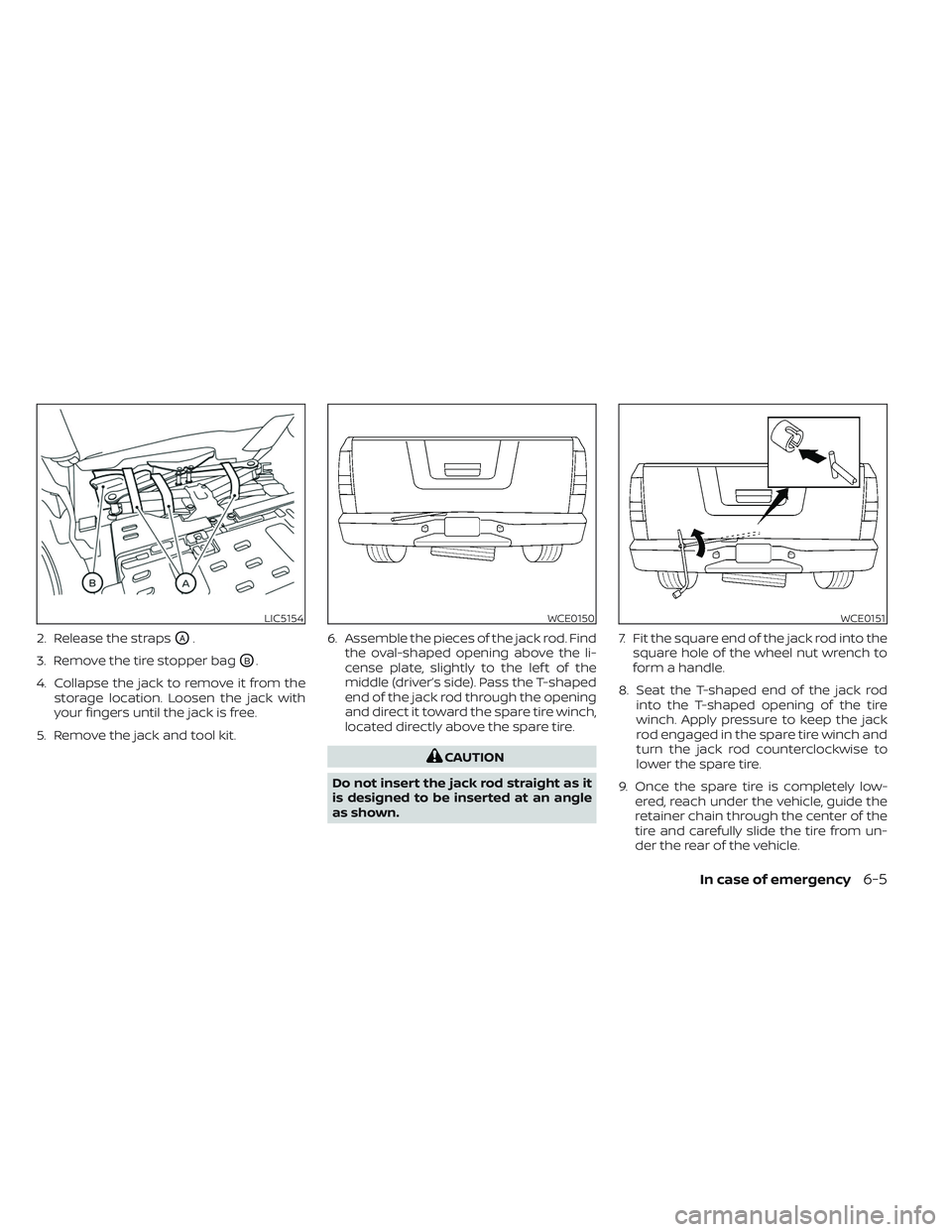
2. Release the strapsOA.
3. Remove the tire stopper bag
OB.
4. Collapse the jack to remove it from the storage location. Loosen the jack with
your fingers until the jack is free.
5. Remove the jack and tool kit. 6. Assemble the pieces of the jack rod. Find
the oval-shaped opening above the li-
cense plate, slightly to the lef t of the
middle (driver’s side). Pass the T-shaped
end of the jack rod through the opening
and direct it toward the spare tire winch,
located directly above the spare tire.
CAUTION
Do not insert the jack rod straight as it
is designed to be inserted at an angle
as shown. 7. Fit the square end of the jack rod into the
square hole of the wheel nut wrench to
form a handle.
8. Seat the T-shaped end of the jack rod into the T-shaped opening of the tire
winch. Apply pressure to keep the jack
rod engaged in the spare tire winch and
turn the jack rod counterclockwise to
lower the spare tire.
9. Once the spare tire is completely low- ered, reach under the vehicle, guide the
retainer chain through the center of the
tire and carefully slide the tire from un-
der the rear of the vehicle.
LIC5154WCE0150WCE0151
In case of emergency6-5
Page 462 of 635
10. Securely store the flat tire beneath thevehicle, from where the full size spare
was removed. To reinstall the wheel, re-
move the center cap (if so equipped)
and insert the retainer chain through
the wheel. Be sure the rubber rim cover
(if so equipped) is centered on the
wheel before lif ting. Use the assembled
jacking rod to slowly rotate the winch
clockwise to raise the wheel to the
vehicle.
11. To reinstall the jack and tool kit, reverse steps 1 through 5.
NOTE:
Inspect the rubber rim cover every six
years and replace as necessary. It is rec-
ommended that you visit a NISSAN
dealer for this service.
CAUTION
• Be sure to center the spare tire sus-
pending plate on the wheel and then
lif t the spare tire.
• Failure to use the rubber rim cover
may allow the chain to get stuck in
the wheel nut holes when stowed.
Removing bolt-on wheel caps (if
so equipped)
CAUTION
Do not use your hands to pry off wheel
caps or wheel covers. Doing so could
result in personal injury.
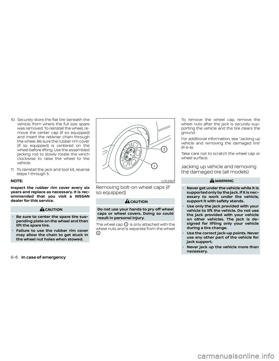
The wheel cap
O1is only attached with the
wheel nuts and is separate from the wheel
O2. To remove the wheel cap, remove the
wheel nuts af ter the jack is securely sup-
porting the vehicle and the tire clears the
ground.
For additional information, see “Jacking up
vehicle and removing the damaged tire”
(P. 6-6).
Take care not to scratch the wheel cap or
wheel surface.
Jacking up vehicle and removing
the damaged tire (all models)
WARNING
• Never get under the vehicle while it is
supported only by the jack. If it is nec-
essary to work under the vehicle,
support it with safety stands.
• Use only the jack provided with your
vehicle to lif t the vehicle. Do not use
the jack provided with your vehicle
on other vehicles. The jack is de-
signed for lif ting only your vehicle
during a tire change.
• Use the correct jack-up points. Never
use any other part of the vehicle for
jack support.
• Never jack up the vehicle more than
necessary.LCE2367
6-6In case of emergency
Page 464 of 635
Carefully read the caution label attached
to the jack body and the following in-
structions.
1. Loosen each wheel nut one or two turnsby turning counterclockwise with the
wheel nut wrench. Do not remove the
wheel nuts until the tire is off the
ground.
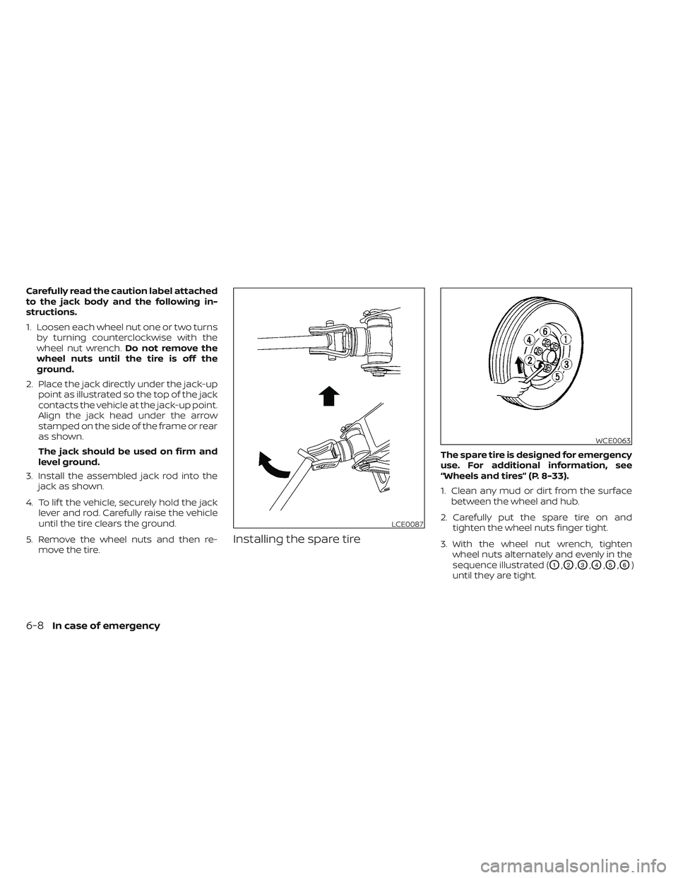
2. Place the jack directly under the jack-up point as illustrated so the top of the jack
contacts the vehicle at the jack-up point.
Align the jack head under the arrow
stamped on the side of the frame or rear
as shown.
The jack should be used on firm and
level ground.
3. Install the assembled jack rod into the jack as shown.
4. To lif t the vehicle, securely hold the jack lever and rod. Carefully raise the vehicle
until the tire clears the ground.
5. Remove the wheel nuts and then re- move the tire.
Installing the spare tire
The spare tire is designed for emergency
use. For additional information, see
“Wheels and tires” (P. 8-33).
1. Clean any mud or dirt from the surfacebetween the wheel and hub.
2. Carefully put the spare tire on and tighten the wheel nuts finger tight.
3. With the wheel nut wrench, tighten wheel nuts alternately and evenly in the
sequence illustrated (
O1,O2,O3,O4,O5,O6)
until they are tight.
LCE0087
WCE0063
6-8In case of emergency
Page 465 of 635
4. Lower the vehicle slowly until the tiretouches the ground. Then, with the
wheel nut wrench, tighten the wheel
nuts securely in the sequence illustrated
(
O1,O2,O3,O4,O5,O6). Lower the vehicle
completely.
WARNING
• Incorrect wheel nuts or improperly
tightened wheel nuts can cause the
wheel to become loose or come off.
This could cause an accident.
• Do not use oil or grease on the wheel
studs or nuts. This could cause the
nuts to become loose.
• Retighten the wheel nuts when the
vehicle has been driven for 600 miles
(1,000 km) (also in cases of a flat tire,
etc.).
As soon as possible, tighten the wheel
nuts to the specified torque with a
torque wrench.
Wheel nut tightening torque:
Non-XD models: 98 f t-lb (133 N·m)
XD models: 131 f t-lb (177 N·m) The wheel nuts must be kept tightened
to specification at all times. It is recom-
mended that wheel nuts be tightened to
specifications at each lubrication
interval.
Adjust tire pressure to the COLD
pressure.
COLD pressure: Af ter vehicle has been
parked for 3 hours or more or driven less
than 1 mi. (1.6 km).
COLD tire pressures are shown on the
Tire and Loading Information label af-
fixed to the driver side center pillar.
Af ter adjusting tire pressure to the COLD
tire pressure, the display (if so equipped)
of the tire pressure information may
show higher pressure than the COLD tire
pressure af ter the vehicle has been
driven more than 1 mi. (1.6 km). This is
because the tire pressure increases as
the tire temperature rises. This does not
indicate a system malfunction.
5. Securely store the tools and jacking
equipment in the vehicle. For additional
information, see the “Getting the spare
tire and tools (Crew and King Cab® mod-
els)” (P. 6-4).
WARNING
• Always make sure that the spare tire
and jacking equipment are properly
secured af ter use. Such items can be-
come dangerous projectiles in an ac-
cident or sudden stop.
• The spare tire is designed for emer-
gency use. For additional informa-
tion, see “Wheels and tires” (P. 8-33).
In case of emergency6-9
Page 513 of 635

Reverse steps to install bulbs and rear
combination light.If you have a flat tire, see “Flat tire”
(P. 6-3).
TIRE PRESSURE
Tire Pressure Monitoring System
(TPMS)
WARNING
Radio waves could adversely af-
fect electric medical equipment.
Those who use a pacemaker
should contact the electric medi-
cal equipment manufacturer for
the possible influences before
use.
This vehicle is equipped with the Tire
Pressure Monitoring System (TPMS).
It monitors tire pressure of all four
tires except the spare. When the low
tire pressure warning light is lit and
the “Tire Pressure Low - Add Air”
warning appears in the vehicle infor-
mation display, one or more of your
tires is significantly under-inflated. If equipped, the system also displays
pressure of all tires (except the spare
tire) on the display screen by send-
ing a signal from a sensor that is
installed in each wheel.
The TPMS will activate only when the
vehicle is driven at speeds above
16 mph (25 km/h). Also, this system
may not detect a sudden drop in tire
pressure (for example a flat tire while
driving).
For additional information, see
“Warning lights, indicator lights and
audible reminders” (P. 2-12), “Tire
Pressure Monitoring System (TPMS)”
(P. 5-5), and “Flat tire” (P. 6-3).
Tire inflation pressure
Check the tire pressures (including
the spare) of ten and always prior to
long distance trips. The recom-
mended tire pressure specifications
are shown on the F.M.V.S.S. certifica-
tion label or the Tire and Loading
WHEELS AND TIRES
Do-it-yourself8-33
Page 523 of 635

CHANGING WHEELS AND TIRES
Tire rotation
NISSAN recommends rotating tires
every 7,500 miles (12,000 km).
For additional information on tire
replacing procedures, see “Flat tire”
(P. 6-3).
As soon as possible, tighten the
wheel nuts to the specified torque
with a torque wrench.Wheel nut tightening torque:
Non-XD models:
98 f t-lb (133 N·m)
XD models: 131 f t-lb (177 N·m)
The wheel nuts must be kept tight-
ened to specifications at all times.
It is recommended that wheel nuts
be tightened to specification at
each tire rotation interval.
WARNING
• Retighten the wheel nuts when
the vehicle has been driven for
600 miles (1,000 km) (also in
cases of a flat tire, etc.).
• Do not include the spare tire in
the tire rotation. •
For additional information re-
garding tires, refer to “Impor-
tant Tire Safety Information”
(US) or “Tire Safety Informa-
tion” (Canada) in the Warranty
Information Booklet.
• Af ter rotating the tires, do not
use the Easy-Fill Tire Alert to
adjust the tire pressure. In-
stead use a gauge to adjust the
tires to the correct pressure in
accordance with Tire and Load-
ing Information label.
CAUTION
To ensure proper operation of the
Easy-Fill Tire Alert system af ter a
tire rotation, re-set and register
the sensor to their new installed
locations. It is recommended that
you visit a NISSAN dealer for this
service.
WDI0258
Do-it-yourself8-43
Page 524 of 635
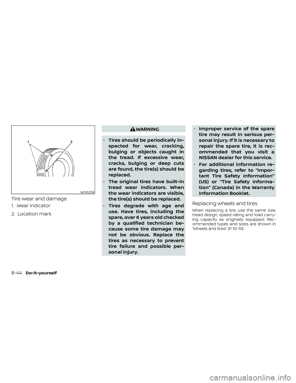
Tire wear and damage
1. Wear indicator
2. Location mark
WARNING
• Tires should be periodically in-
spected for wear, cracking,
bulging or objects caught in
the tread. If excessive wear,
cracks, bulging or deep cuts
are found, the tire(s) should be
replaced.
• The original tires have built-in
tread wear indicators. When
the wear indicators are visible,
the tire(s) should be replaced.
• Tires degrade with age and
use. Have tires, including the
spare, over 6 years old checked
by a qualified technician be-
cause some tire damage may
not be obvious. Replace the
tires as necessary to prevent
tire failure and possible per-
sonal injury. •
Improper service of the spare
tire may result in serious per-
sonal injury. If it is necessary to
repair the spare tire, it is rec-
ommended that you visit a
NISSAN dealer for this service.
• For additional information re-
garding tires, refer to “Impor-
tant Tire Safety Information”
(US) or “Tire Safety Informa-
tion” (Canada) in the Warranty
Information Booklet.
Replacing wheels and tires
When replacing a tire, use the same size,
tread design, speed rating and load carry-
ing capacity as originally equipped. Rec-
ommended types and sizes are shown in
“Wheels and tires” (P. 10-10).
WDI0259
8-44Do-it-yourself
Page 525 of 635

WARNING
• The use of tires other than those rec-
ommended or the mixed use of tires
of different brands, construction
(bias, bias-belted or radial), or tread
patterns can adversely affect the
ride, braking, handling, Vehicle Dy-
namic Control (VDC) system, 4WD,
ground clearance, body-to-tire clear-
ance, tire chain clearance, speedom-
eter calibration, headlight aim and
bumper height. Some of these ef-
fects may lead to accidents and
could result in serious personal
injury.
• If your vehicle was originally
equipped with four tires that were
the same size and you are only re-
placing two of the four tires, install
the new tires on the rear axle. Placing
new tires on the front axle may cause
loss of vehicle control in some driving
conditions and cause an accident
and personal injury. •
If the wheels are changed for any
reason, always replace with wheels
which have the same off-set dimen-
sion. Wheels of a different off-set
could cause premature tire wear, de-
grade vehicle handling characteris-
tics, affect the VDC system and/or in-
terference with the brake discs. Such
interference can lead to decreased
braking efficiency and/or early brake
pad/shoe wear. For additional infor-
mation on wheel-off set dimensions,
see “Wheels and tires” (P. 10-10).
• When using a wheel without the
TPMS such as the spare tire, the TPMS
will not function and the low tire
pressure warning light will flash for
approximately 1 minute. The light will
remain on af ter 1 minute. Have your
tires replaced and/or TPMS system
reset as soon as possible. It is recom-
mended that you visit a NISSAN
dealer for this service.
• Replacing tires with those not origi-
nally specified by NISSAN could af-
fect the proper operation of the
TPMS.
• The TPMS sensor may be damaged if
it is not handled correctly. Be careful
when handling the TPMS sensor. •
When replacing the TPMS sensor, the
ID registration may be required. Con-
tact a NISSAN dealer for ID
registration.
• Do not use a valve stem cap that is
not specified by NISSAN. The valve
stem cap may become stuck.
• Be sure that the valve stem caps are
correctly fitted. Otherwise the valve
may be clogged up with dirt and
cause a malfunction or loss of
pressure.
• Do not install a damaged or de-
formed wheel or tire even if it has
been repaired. Such wheels or tires
could have structural damage and
could fail without warning.
• The use of retread tires is not
recommended.
• For additional information regarding
tires, refer to “Important Tire Safety
Information” (US) or “Tire Safety In-
formation” (Canada) in the Warranty
Information Booklet.
Do-it-yourself8-45