2022 NISSAN TITAN charging
[x] Cancel search: chargingPage 284 of 635

• When you change the air flow mode, youmay feel air flow from the foot outlets for
just a moment. This is not a malfunction.
• When the ignition is placed in the ON po- sition, in some fogging or high cabin
temp conditions, air may flow automati-
cally to the foot outlets for 3 to 7 seconds
to purge the hot air in the system. The air conditioner system in your NISSAN
vehicle is charged with a refrigerant de-
signed with the environment in mind.
This refrigerant does not harm the
earth's ozone layer.
Special charging equipment and lubricant
is required when servicing your NISSAN air
conditioner. Using improper refrigerants or
lubricants will cause severe damage to
your air conditioner system. For additional
information, see “Air conditioner system re-
frigerant and oil recommendations”
(P. 10-8).
It is recommended that you visit a NISSAN
dealer to service your “environmentally
friendly” air conditioner system.
WARNING
The air conditioner system contains re-
frigerant under high pressure. To avoid
personal injury, any air conditioner ser-
vice should be done only by an experi-
enced technician with proper
equipment. The vehicle is equipped with a shark fin
antenna.
SERVICING AIR CONDITIONER
ANTENNA
4-42Monitor, climate, audio, phone and voice recognition systems
Page 289 of 635

CONTROL DESCRIPTION
1.SD Card Slot
Play videos, music, and images stored on
most SD cards. The full-size SD card slot is accessible on
the lef t side of the monitor when the
screen is in the open position.2.
Screen latch
Press the push-button latch located on
the top of the monitor to pivot the
screen. Remember to turn the monitor
off and pivot the screen to the locked
(latched) position when not in use.
3. Power (Monitor A)
Press this button to turn the monitor on.
Press again to turn the monitor off. Press
and hold for 6 seconds to reset the sys-
tem (Monitor A only)
Power (Monitor B)
Press this button to turn the monitor on.
Press again to turn the monitor off.
4. Front panel controls
Capacitive-touch buttons provide user
interface navigation, Select, Back, and
Home functions.
5. Monitor screen display
Includes an 8-inch TFT Liquid Crystal
Display with 1024 x 600 resolution.
6. HDMI port
Connect an external audio/video source
using a full-size HDMI connector. Sup-
ports MHL 2.0 playback and charging.
LHA5995
Monitor A (Driver’s Side)
Monitor, climate, audio, phone and voice recognition systems4-47
Page 320 of 635

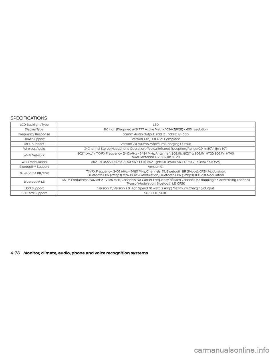
SPECIFICATIONS
LCD Backlight TypeLED
Display Type 8.0 inch (Diagonal) a-Si TFT Active Matrix, 1024x3(RGB) x 600 resolution
Frequency Response 3.5mm Audio Output: 200Hz ~ 16kHz +/- 6dB
HDMI Support Version 1.4b, HDCP 2.1 Compliant
MHL Support Version 2.0, 900mA Maximum Charging Output
Wireless Audio 2-Channel Stereo Headphone Operation, (Typical Infrared Reception/Range: 0.9m; 80°, 1.8m; 50°)
Wi-Fi Network 802.11b/g/n, TX/RX Frequency: 2412 MHz - 2484 MHz, Antenna 1: 802.11b, 802.11g, 802.11n HT20, 802.11n HT40,
MIMO Antenna 1+2: 802.11n HT20
Wi-Fi Modulation 802.11b: DSSS (DBPSK / DQPSK / CCK), 802.11g/n: OFDM (BPSK / QPSK / 16QAM / 64QAM)
Bluetooth® Support Version 4.1
Bluetooth® BR/EDR TX/RX Frequency: 2402 MHz - 2480 MHz, Channels: 79, Bluetooth BR (1Mbps): GFSK Modulation,
Bluetooth EDR (2Mbps): π/4-DQPSK Modulation, Bluetooth EDR (3Mbps): 8-DPSK Modulation
Bluetooth® LE TX/RX Frequency: 2402 MHz - 2480 MHz, Channels: 40, Carrier Frequency of Each Channel:, (37 hoppin
g+3Advertisingchannel),
Type of Modulation: Bluetooth LE: GFSK
USB Support Version 1.1, Version 2.0 High Speed, 10 watt (2 Amp) Maximum Charging Output
SD Card Support SD, SDHC, SDXC
4-78Monitor, climate, audio, phone and voice recognition systems
Page 467 of 635

WARNING
Always follow the instructions below.
Failure to do so could result in damage
to the charging system and cause per-
sonal injury.
1. If the booster battery is in another ve- hicle, position the two vehicles to bring
their batteries near each other.
Do not allow the two vehicles to touch.
2. Apply the parking brake. Move the shif t lever to P (Park). Switch off all unneces-
sary electrical systems (lights, heater, air
conditioner, etc.). 3. Place the ignition switch in the LOCK
position.
4. Ensure the vent caps (if so equipped) are level and tight.
5. Connect the jumper cables in the se- quence illustrated (
OA,OB,OC,OD).
CAUTION
• Always connect positive (+) to posi-
tive (+) and negative (−) to body
ground (for example, strut mounting
bolt, engine lif t bracket, etc.) — not to
the battery. •
Make sure the jumper cables do not
touch moving parts in the engine
compartment and that the cable
clamps do not contact any other
metal.
6. Start the engine of the booster vehicle and let it run for a few minutes.
7. Keep the engine speed of the booster vehicle at about 2,000 rpm and start the
engine of the vehicle being jump started.
CAUTION
Do not keep the starter motor engaged
for more than 10 seconds. If the engine
does not start right away, place the ig-
nition switch in the OFF position and
wait 3 to 4 seconds before trying again.
8. Af ter starting the engine, carefully dis- connect the negative cable and then
the positive cable.
LCE2223
In case of emergency6-11
Page 499 of 635

NOTE:
Do not try to open the top of the battery.
The Type B battery is not equipped with
removable vent caps.
JUMP STARTING
If jump starting is necessary, see “Jump
starting” (P. 6-10). If the engine does not
start by jump starting, the battery may
have to be replaced. It is recommended
that you visit a NISSAN dealer for this
service.
CAUTION
• Do not ground accessories directly to
the battery terminal. Doing so will
bypass the variable voltage control
system and the vehicle battery may
not charge completely.
• Use electrical accessories with the
engine running to avoid discharging
the vehicle battery.
NOTE:
If the battery is completely drained the
transmission will not manually shif t to
other positions.
Your vehicle is equipped with a variable
voltage control system. This system mea-
sures the amount of electrical discharge
from the battery and controls voltage gen-
erated by the generator.
The current sensor is located near the bat-
tery along the negative battery cable. If you
add electrical accessories to your vehicle,
be sure to ground them to a suitable body
ground such as the frame or engine block
area.
LDI3302
Battery (Type B) (if so equipped)
LDI2132
VARIABLE VOLTAGE CONTROL
SYSTEM (if so equipped)
Do-it-yourself8-19
Page 629 of 635

T
Tachometer...................2-8Tailgate.................... .3-34Temperature gauge
Engine coolant temperature gauge. . .2-8Thef t (NISSAN Vehicle Immobilizer System),
engine start...............2-40, 5-16Three-way catalyst...............5-4Tie down hooks................3-38TireFlat tire................... .6-3Spare tire...............6-4, 8-46Tire and Loading Information label. .10-17Tire chains.................8-42Tire pressure................8-33Tire rotation.................8-43Tires of 4-wheel drive...........8-46Types of tires................8-41Uniform tire quality grading......10-55Wheel/tire size...............10-10Wheels and tires..........8-33, 10-10Tire pressure................. .8-33Low tire pressure warning light.....2-18Tire Pressure Monitoring System
(TPMS)................... .5-5, 6-3Tow mode switch...............2-63Towing
2-wheel drive models...........6-15Flat towing................ .10-54Towing load/specification.......10-36Trailer towing...............10-32Towing a trailer................10-32Towing your vehicle..............6-13
Traffic Sign Recognition (TSR)........5-24Trailer Brake Controller Unit (TBCU). . . .2-63Transceiver
HomeLink® Universal
Transceiver
.......2-90, 2-91, 2-93, 2-94Transfer case shif ting procedures. . . .5-108TransmissionDriving with automatic
transmission
................5-19Travel (See registering a vehicle in
another country)...............10-15Trip odometer..................2-7Truck - camper loading...........10-30Truck box................... .3-34Turn signal switch...............2-51
U
Under seat storage bin.....2-71,2-75,2-76Uniform tire quality grading........10-55USB/iPod® Charging Ports.........2-68Using 4-wheel drive.............5-107
V
Vanity mirror..................3-28Variable voltage control system......8-19Vehicle dimensions and weights.....10-11Vehicle Dynamic Control (VDC) OFF
switch..................... .2-58Vehicle Dynamic Control (VDC)
system.....................5-120Vehicle identification.............10-15
Vehicle identification number (VIN). . . .10-15Vehicle identification number (VIN)
(Chassis number)..............10-15Vehicle identification number (VIN)
plate...................... .10-15Vehicle immobilizer system.....2-40, 5-16Vehicle information display.........2-23Vehicle loading information........10-20Vehicle recovery.............6-15,6-16Vehicle security system...........2-39Vehicle security system (NISSAN
Vehicle Immobilizer System),
engine start
...............2-40, 5-16Vents......................4-28Visors......................3-28Voltmeter....................2-10
W
Warning
Air bag warning light........1-83, 2-16Battery charge warning light......2-15Brake warning light............2-14Engine oil pressure warning light. . . .2-15Hazard warning flasher switch......6-2Loose fuel cap warning..........2-33Low fuel warning
light............2-16,2-21, 2-33, 2-34Low tire pressure warning light.....2-18Low windshield-washer fluid
warning light................2-33Passenger air bag and status light. . .1-63Seat belt warning light..........2-16
11-7