2022 NISSAN SENTRA ECU
[x] Cancel search: ECUPage 192 of 528
CONDITIONS THE REMOTE ENGINE
START WILL NOT WORK
The Remote Engine Start will not operate if
any of the following conditions are present:
• “Remote Engine Start” is turned off in the“Vehicle Settings” menu of the vehicle in-
formation display.
• The ignition switch is placed in the ON position.
• The hood is not securely closed.
• The hazard indicator lights are on.
• The engine is still running. The engine must be completely stopped. Wait at
least 6 seconds if the engine goes from
running to off. This is not applicable when
extending engine run time.
• The
button is not pressed and held
for at least 2 seconds.
• The
button is not pressed and held
within 5 seconds of pressing the lock but-
ton.
• The brake is pressed.
• The doors are not closed and locked.
• The trunk is open.
• The Key System Error warning shows in the vehicle information display.
• The alarm sounds due to illegal entry into the vehicle. • Two Remote Engine Starts, or a single
Remote Engine Start with an extension,
have already been used.
• The vehicle is not in P (Park).
• There is a detected registered key already inside of the vehicle.
• The Remote Engine Start function has been switched to the OFF position in “Ve-
hicle Settings” of the vehicle information
display. For additional information, refer
to “Vehicle information display” in the “In-
struments and controls” section of this
manual.
The Remote Engine Start may display a
warning or indicator in the vehicle informa-
tion display. For additional information, re-
fer to “Vehicle information display” in the
“Instruments and controls” section of this
manual.
3-22Pre-driving checks and adjustments
Page 290 of 528
WARNING
• Do not leave children or adults who
would normally require the assis-
tance of others alone in your vehicle.
Pets should also not be lef t alone.
They could accidentally injure them-
selves or others through inadvertent
operation of the vehicle. Also, on hot,
sunny days, temperatures in a closed
vehicle could quickly become high
enough to cause severe or possibly
fatal injuries to people or animals.
• Closely supervise children when they
are around cars to prevent them
from playing and becoming locked in
the trunk where they could be seri-
ously injured. Keep the car locked,
with the rear seatback and trunk lid
securely latched when not in use, and
prevent children's access to car keys.
EXHAUST GAS (carbon monoxide)
air recirculation but-
ton to off and the fan control dial
to high to circulate the air.
• If electrical wiring or other cable con-
nections must pass to a trailer
through the seal on the trunk lid or
the body, follow the manufacturer's
recommendation to prevent carbon
monoxide entry into the vehicle. •
The exhaust system and body should
be inspected by a qualified mechanic
whenever:
a. The vehicle is raised for service.
b. You suspect that exhaust fumes are entering into the passenger
compartment.
c. You notice a change in the sound of the exhaust system.
d. You have had an accident involv- ing damage to the exhaust sys-
tem, underbody, or rear of the
vehicle.
THREE-WAY CATALYST
The three-way catalyst is an emission con-
trol device installed in the exhaust system.
Exhaust gases in the three-way catalyst
are burned at high temperatures to help
reduce pollutants.
Page 297 of 528
WARNING
Do not operate the push-button igni-
tion switch while driving the vehicle ex-
cept in an emergency. (The engine will
stop when the ignition switch is pushed
three consecutive times in quick suc-
cession or the ignition switch is pushed
and held for more than 2 seconds.) If
the engine stops while the vehicle is
being driven, this could lead to a crash
and serious injury. When the ignition switch is pushed without
depressing the brake pedal or the clutch
pedal for manual transmission (M/T) mod-
els, the ignition switch position will illumi-
nate as follows:
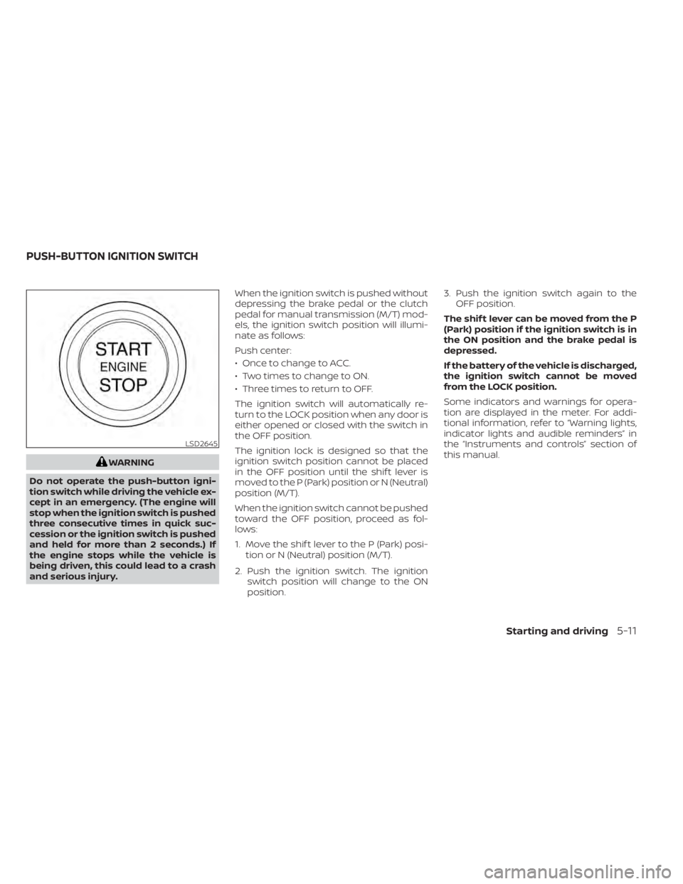
Push center:
• Once to change to ACC.
• Two times to change to ON.
• Three times to return to OFF.
The ignition switch will automatically re-
turn to the LOCK position when any door is
either opened or closed with the switch in
the OFF position.
The ignition lock is designed so that the
ignition switch position cannot be placed
in the OFF position until the shif t lever is
moved to the P (Park) position or N (Neutral)
position (M/T).
When the ignition switch cannot be pushed
toward the OFF position, proceed as fol-
lows:
1. Move the shif t lever to the P (Park) posi-
tion or N (Neutral) position (M/T).
2. Push the ignition switch. The ignition switch position will change to the ON
position. 3. Push the ignition switch again to the
OFF position.
The shif t lever can be moved from the P
(Park) position if the ignition switch is in
the ON position and the brake pedal is
depressed.
If the battery of the vehicle is discharged,
the ignition switch cannot be moved
from the LOCK position.
Some indicators and warnings for opera-
tion are displayed in the meter. For addi-
tional information, refer to “Warning lights,
indicator lights and audible reminders” in
the “Instruments and controls” section of
this manual.
LSD2645
PUSH-BUTTON IGNITION SWITCH
Starting and driving5-11
Page 421 of 528
Always refer to the illustrations for the cor-
rect placement and jack-up points for your
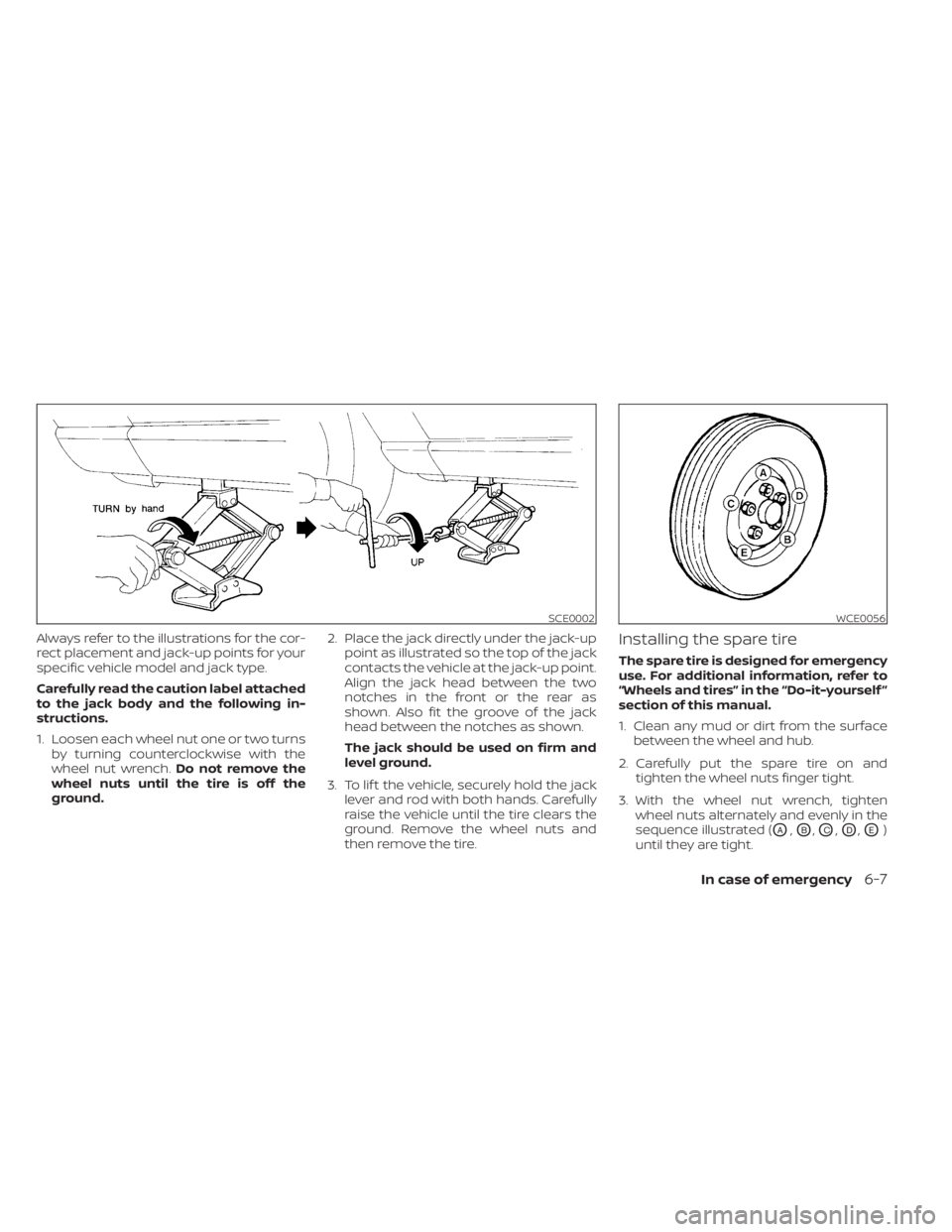
specific vehicle model and jack type.
Carefully read the caution label attached
to the jack body and the following in-
structions.
1. Loosen each wheel nut one or two turnsby turning counterclockwise with the
wheel nut wrench. Do not remove the
wheel nuts until the tire is off the
ground. 2. Place the jack directly under the jack-up
point as illustrated so the top of the jack
contacts the vehicle at the jack-up point.
Align the jack head between the two
notches in the front or the rear as
shown. Also fit the groove of the jack
head between the notches as shown.
The jack should be used on firm and
level ground.
3. To lif t the vehicle, securely hold the jack lever and rod with both hands. Carefully
raise the vehicle until the tire clears the
ground. Remove the wheel nuts and
then remove the tire.Installing the spare tire
The spare tire is designed for emergency
use. For additional information, refer to
“Wheels and tires” in the “Do-it-yourself ”
section of this manual.
1. Clean any mud or dirt from the surfacebetween the wheel and hub.
2. Carefully put the spare tire on and tighten the wheel nuts finger tight.
3. With the wheel nut wrench, tighten wheel nuts alternately and evenly in the
sequence illustrated (
OA,OB,OC,OD,OE)
until they are tight.
SCE0002WCE0056
Page 422 of 528
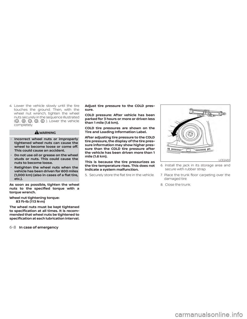
4. Lower the vehicle slowly until the tiretouches the ground. Then, with the
wheel nut wrench, tighten the wheel
nuts securely in the sequence illustrated
(
OA,OB,OC,OD,OE). Lower the vehicle
completely.
LCE2451
6-8In case of emergency
Page 423 of 528
WARNING
• Always make sure that the spare tire
and jacking equipment are properly
secured af ter use. Such items can be-
come dangerous projectiles in an ac-
cident or sudden stop.
• The spare tire is designed for emer-
gency use. Refer to specific instruc-
tions under the heading “Wheels and
tires” in the “Do-it-yourself ” section
of this manual. To start your engine with a booster battery,
the instructions and precautions below
must be followed.
Page 437 of 528
When installing Genuine NISSAN floor mats,
follow the installation instructions provided
with the mat and the following:
1. With the ignition in the OFF position, theshif t lever in P (Park) position (Continu-
ously Variable Transmission models) or
the shif t lever in the N (Neutral) position
(manual transmission models) and with
the parking break fully applied, position
the floor mat in the floorwell so that the
floor mat grommet holes are aligned
with the hook(s).
2. Secure the grommet holes into the hook(s) and ensure that the floor mat is
properly positioned.
3. Make sure the floor mat does not inter- fere with pedal operation. With the igni-
tion still in the OFF position, the shif t le-
ver in the P (Park) position (Continuously
Variable Transmission models) or the
shif t lever in the N (Neutral) position
(manual transmission models) and with
the parking break applied, fully apply
and release all pedals. The floor mat
must not interfere with pedal operation
or prevent the pedal from returning to
its normal position. It is recommended that you visit a NISSAN
dealer for details about installing the floor
mats in your vehicle.
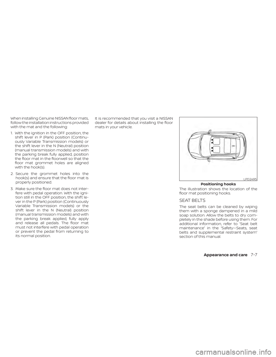
The illustration shows the location of the
floor mat positioning hooks.
SEAT BELTS
The seat belts can be cleaned by wiping
them with a sponge dampened in a mild
soap solution. Allow the belts to dry com-
pletely in the shade before using them. For
additional information, refer to “Seat belt
maintenance” in the “Safety—Seats, seat
belts and supplemental restraint system”
section of this manual.
LPD2495
Positioning hooks
Appearance and care7-7
Page 453 of 528
• If the battery is labeled “do not open” it ismaintenance free and battery fluid
should not be checked. It is recom-
mended that you visit a NISSAN dealer or
a qualified specialist workshop to con-
firm the battery’s performance.
• Keep the battery surface clean and dry. Clean the battery with a solution of bak-
ing soda and water.
• Make certain the terminal connections are clean and securely tightened.
• If the vehicle is not to be used for 30 days or longer, disconnect the negative (-) bat-
tery terminal cable to prevent discharge.
NOTE:
Care should be taken to avoid situations
that can lead to potential battery dis-
charge and potential no-start conditions
such as:
1. Installation or extended use of elec-
tronic accessories that consume bat-
tery power when the engine is not run-
ning (Phone chargers, GPS, DVD
players, etc.)
2. Vehicle is not driven regularly and/or
only driven short distances.
In these cases, the battery may need to
be charged to maintain battery health.
WARNING
• Do not expose the battery to flames,
an electrical spark or a cigarette. Hy-
drogen gas generated by the battery
is explosive. Explosive gases can
cause blindness or injury. Do not al-
low battery fluid to contact your skin,
eyes, fabrics or painted surfaces. Sul-
furic acid can cause blindness or in-
jury. Af ter touching a battery or bat-
tery cap, do not touch or rub your
eyes. Thoroughly wash your hands. If
the acid contacts your eyes, skin or
clothing, immediately flush with wa-
ter for at least 15 minutes and seek
medical attention.
• When working on or near a battery,
always wear suitable eye protection
and remove all jewelry.
• Battery posts, terminals and related
accessories contain lead and lead
compounds. Wash hands af ter
handling.
• Keep battery out of the reach of
children.
• Do not tip the battery.
NOTE:
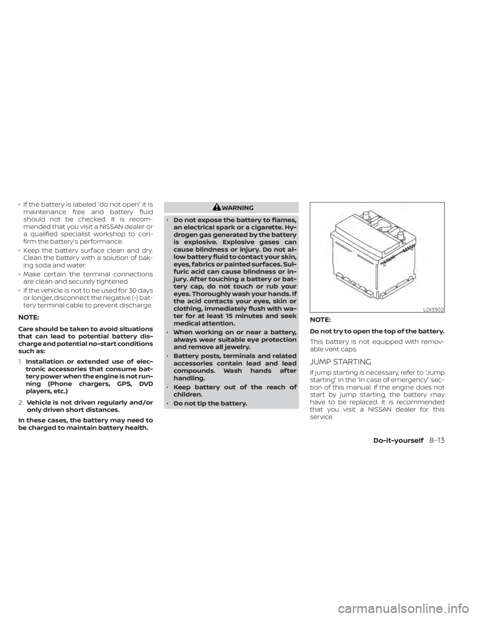
Do not try to open the top of the battery.
This battery is not equipped with remov-
able vent caps.
JUMP STARTING
If jump starting is necessary, refer to “Jump
starting” in the “In case of emergency” sec-
tion of this manual. If the engine does not
start by jump starting, the battery may
have to be replaced. It is recommended
that you visit a NISSAN dealer for this
service.
LDI3302