Page 308 of 528
•When the vehicle is stopped with the
engine running (for example, at a
stop light), shif t to N (Neutral) and re-
lease the clutch pedal with the foot
brake applied.
• Do not shif t to the N (Neutral) posi-
tion while driving. Doing so may re-
sult in an accident due to loss of en-
gine braking.
Shif ting
To change gears or when upshif ting or
downshif ting, depress the clutch pedal
fully, shif t into the appropriate gear, then
release the clutch slowly and smoothly.
To ensure smooth gear changes, fully de-
press the clutch pedal before operating the
shif t lever. If the clutch pedal is not fully
depressed before the transmission is
shif ted, a gear noise may be heard. Trans-
mission damage may occur.
Start the vehicle in 1st gear and shif t to 2nd,
3rd, 4th and 5th up to 6th gear in sequence
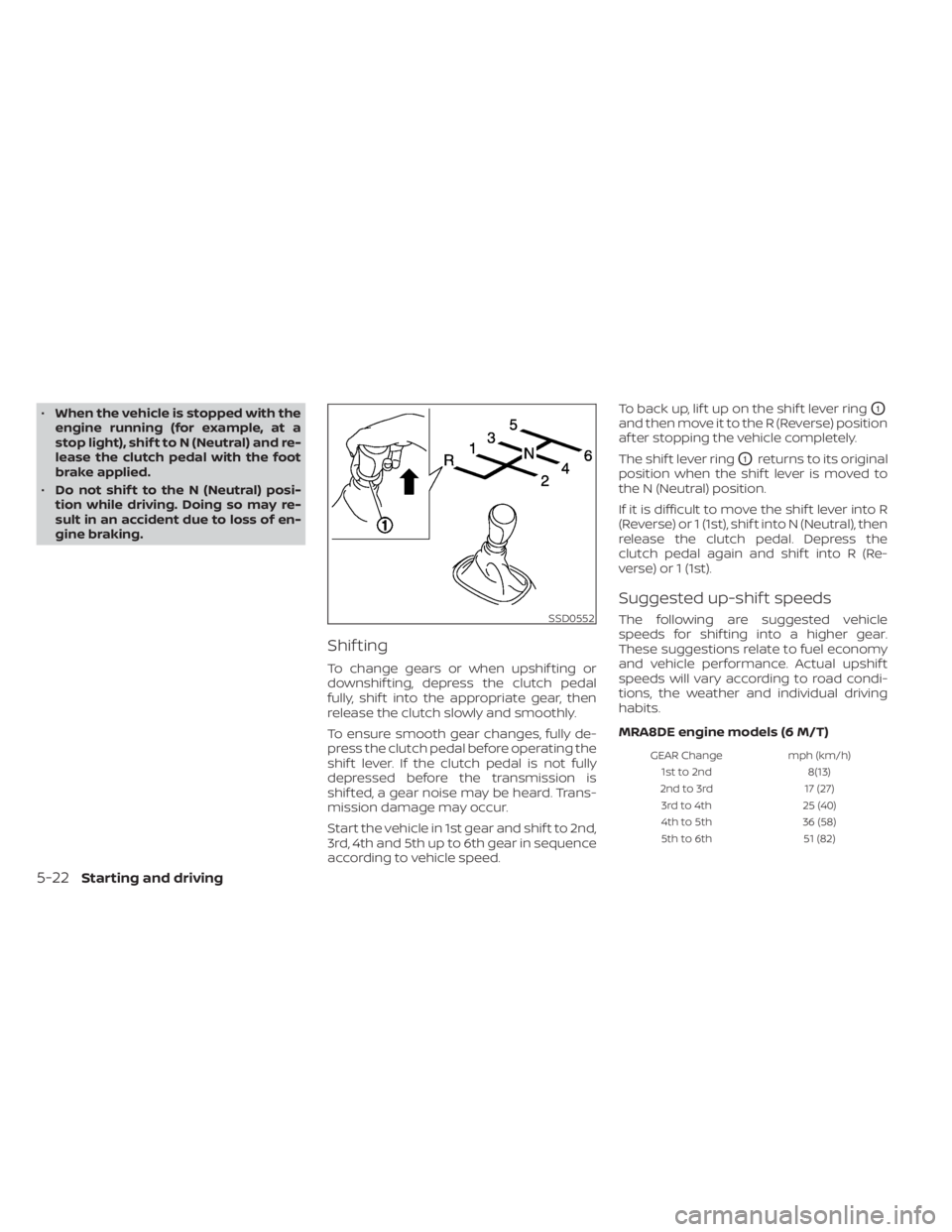
according to vehicle speed. To back up, lif t up on the shif t lever ring
O1
and then move it to the R (Reverse) position
af ter stopping the vehicle completely.
The shif t lever ring
O1returns to its original
position when the shif t lever is moved to
the N (Neutral) position.
If it is difficult to move the shif t lever into R
(Reverse) or 1 (1st), shif t into N (Neutral), then
release the clutch pedal. Depress the
clutch pedal again and shif t into R (Re-
verse) or 1 (1st).
Suggested up-shif t speeds
The following are suggested vehicle
speeds for shif ting into a higher gear.
These suggestions relate to fuel economy
and vehicle performance. Actual upshif t
speeds will vary according to road condi-
tions, the weather and individual driving
habits.
MRA8DE engine models (6 M/T)
GEAR Change mph (km/h)
1st to 2nd 8(13)
2nd to 3rd 17 (27)
3rd to 4th 25 (40)
4th to 5th 36 (58)
5th to 6th 51 (82)
SSD0552
5-22Starting and driving
Page 310 of 528
To engage:Pull the lever upOA.
To release:
1. Firmly apply the foot brake.
2. Manual transmission models:
Place the shif t lever in the N (Neutral)
position.
Continuously Variable Transmission
models:
Move the shif t lever to the P (Park) posi-
tion. 3. While pulling up on the parking brake
lever slightly, press the button and lower
completely
OB.
4. Before driving, be sure the brake warn- ing light goes out.
To engage:Firmly depress the parking
brake.
To release:
1. Firmly apply the foot brake.
2. Move the shif t lever to the P (Park) position.
3. Firmly depress the parking brake pedal and it will release.
4. Before driving, be sure the brake warn- ing light goes out.
LSD2197LSD0158
PEDAL TYPE
Page 311 of 528
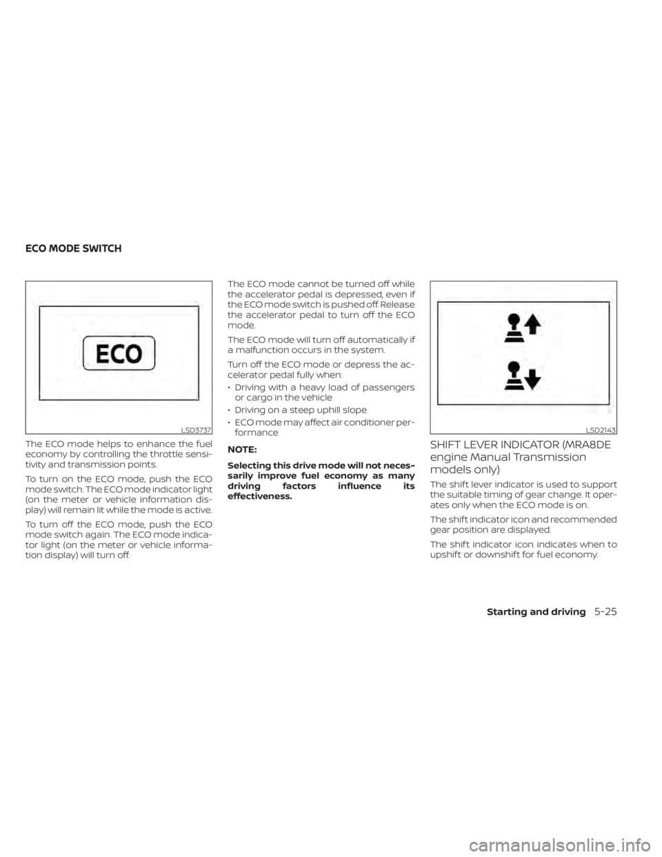
The ECO mode helps to enhance the fuel
economy by controlling the throttle sensi-
tivity and transmission points.
To turn on the ECO mode, push the ECO
mode switch. The ECO mode indicator light
(on the meter or vehicle information dis-
play) will remain lit while the mode is active.
To turn off the ECO mode, push the ECO
mode switch again. The ECO mode indica-
tor light (on the meter or vehicle informa-
tion display) will turn off.The ECO mode cannot be turned off while
the accelerator pedal is depressed, even if
the ECO mode switch is pushed off. Release
the accelerator pedal to turn off the ECO
mode.
The ECO mode will turn off automatically if
a malfunction occurs in the system.
Turn off the ECO mode or depress the ac-
celerator pedal fully when:
• Driving with a heavy load of passengers
or cargo in the vehicle
• Driving on a steep uphill slope
• ECO mode may affect air conditioner per- formanceNOTE:
Selecting this drive mode will not neces-
sarily improve fuel economy as many
driving factors influence its
effectiveness.
SHIFT LEVER INDICATOR (MRA8DE
engine Manual Transmission
models only)
The shif t lever indicator is used to support
the suitable timing of gear change. It oper-
ates only when the ECO mode is on.
The shif t indicator icon and recommended
gear position are displayed.
The shif t indicator icon indicates when to
upshif t or downshif t for fuel economy.
LSD3737LSD2143
ECO MODE SWITCH
Starting and driving5-25
Page 314 of 528
–When rain, snow or dirt adheres to
the windshield in front of the
multi-sensing camera unit.
– When the headlights are not
bright due to dirt on the lens or if
the aiming is not adjusted
properly.
– When strong light enters the cam-
era unit. (For example, the light di-
rectly shines on the front of the
vehicle at sunrise or sunset.)
– When a sudden change in bright-
ness occurs. (For example, when
the vehicle enters or exits a tunnel
or under a bridge.)
– In areas not covered by the navi-
gation system.
– If there are deviations in relation
to the navigation, for example due
to changes in the road routing.
– When overtaking buses or trucks
with speed stickers.
TURNING THE TRAFFIC SIGN
RECOGNITION (TSR) SYSTEM ON
AND OFF
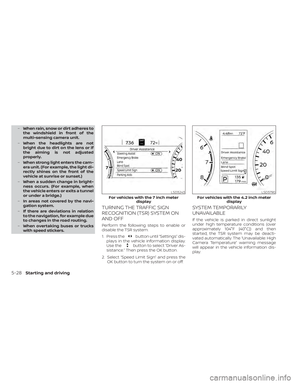
Perform the following steps to enable or
disable the TSR system.
1. Press the
button until “Settings” dis-
plays in the vehicle information display.
Use the
button to select “Driver As-
sistance.” Then press the OK button.
2. Select “Speed Limit Sign” and press the OK button to turn the system on or off.
SYSTEM TEMPORARILY
UNAVAILABLE
If the vehicle is parked in direct sunlight
under high temperature conditions (over
approximately 104°F [40°C]) and then
started, the TSR system may be deacti-
vated automatically. The “Unavailable: High
Camera Temperature” warning message
will appear in the vehicle information dis-
play.
LSD3243
For vehicles with the 7 inch meter display
Page 320 of 528
•The system may not function prop-
erly under the following conditions:
– On roads where there are multiple
parallel lane markers; lane mark-
ers that are faded or not painted
clearly; yellow painted lane mark-
ers; non-standard lane markers;
or lane markers covered with wa-
ter, dirt, snow, etc.
– On roads where the discontinued
lane markers are still detectable.
– On roads where there are sharp
curves.
– On roads where there are sharply
contrasting objects, such as shad-
ows, snow, water, wheel ruts,
seams or lines remaining af ter
road repairs. (The LDW system
could detect these items as lane
markers.)
– On roads where the traveling lane
merges or separates.
– When the vehicle’s traveling direc-
tion does not align with the lane
marker.
– When traveling close to the ve-
hicle in front of you, which ob-
structs the lane camera unit de-
tection range. –
When rain, snow, dirt or an object
adheres to the windshield in front
of the lane camera unit.
– When the headlights are not
bright due to dirt on the lens or if
the aiming is not adjusted
properly.
– When strong light enters the lane
camera unit. (For example, the
light directly shines on the front of
the vehicle at sunrise or sunset.)
– When a sudden change in bright-
ness occurs. (For example, when
the vehicle enters or exits a tunnel
or under a bridge.)
SYSTEM TEMPORARILY
UNAVAILABLE
If the vehicle is parked in direct sunlight
under high temperature conditions (over
approximately 104°F [40°C]) and then
started, the LDW system may be deacti-
vated automatically and the following
message will appear in the vehicle infor-
mation display: “Unavailable: High Cabin
Temperature.”
When the interior temperature is reduced,
the LDW system will resume operating au-
tomatically. The LDW system is not designed to warn
under the following conditions:
• When you operate the lane change signal
and change traveling lanes in the direc-
tion of the signal. (The LDW system will
become operable again approximately 2
seconds af ter the lane change signal is
turned off.)
• When the vehicle speed lowers to less than approximately 37 mph (60 km/h).
Af ter the above conditions have finished
and the necessary operating conditions
are satisfied, the LDW functions will resume.
SYSTEM MALFUNCTION
If the LDW system malfunctions, it will can-
cel automatically and “Not Available Sys-
tem Malfunction” will appear in the vehicle
information display. If “Not Available Sys-
tem Malfunction” appears in the vehicle in-
formation display, pull off the road to a safe
location and stop the vehicle. Place the
shif t lever in the P (Park) position and the
ignition switch in the OFF position and re-
start the engine/motor. If “Not Available
System Malfunction” continues to appear
in the vehicle information display, have the
system checked. It is recommended that
you visit a NISSAN dealer for this service.
5-34Starting and driving
Page 321 of 528
SYSTEM MAINTENANCE
The lane camera unitO1for the LDW sys-
tem is located above the inside mirror. To
keep the proper operation of the LDW sys-
tem and prevent a system malfunction, be
sure to observe the following:
• Always keep the windshield clean.
• Do not attach a sticker (including trans- parent material) or install an accessory
near the camera unit. • Do not place reflective materials, such as
white paper or a mirror, on the instru-
ment panel. The reflection of sunlight
may adversely affect the camera unit’s
capability of detecting the lane markers.
• Do not strike or damage the areas around the camera unit. Do not touch the
camera lens or remove the screw located
on the camera unit. If the camera unit is
damaged due to an accident, it is recom-
mended that you visit a NISSAN dealer.
LSD3484
BLIND SPOT WARNING (BSW)
Starting and driving5-35
Page 323 of 528
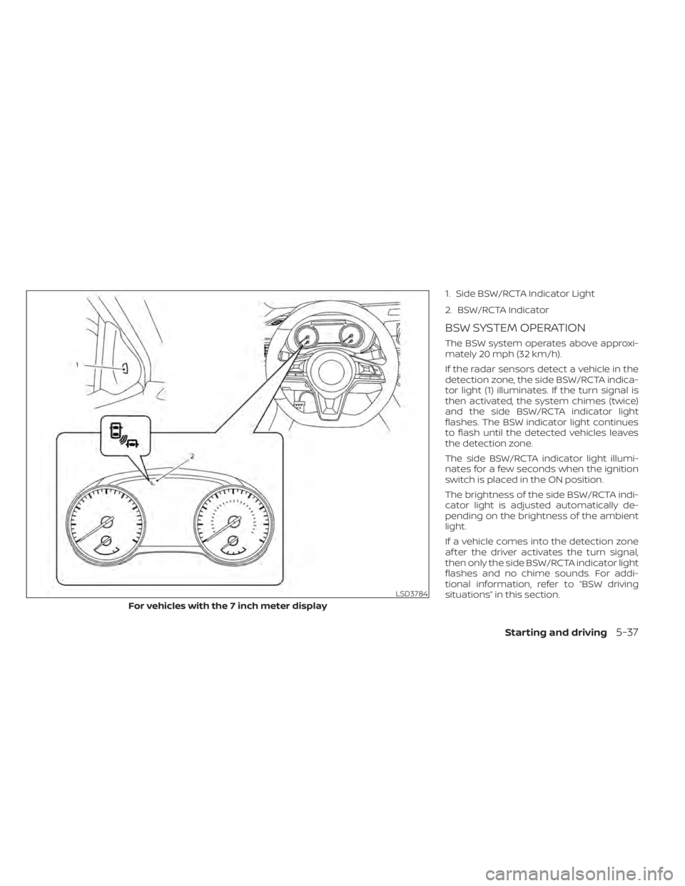
1. Side BSW/RCTA Indicator Light
2. BSW/RCTA Indicator
BSW SYSTEM OPERATION
The BSW system operates above approxi-
mately 20 mph (32 km/h).
If the radar sensors detect a vehicle in the
detection zone, the side BSW/RCTA indica-
tor light (1) illuminates. If the turn signal is
then activated, the system chimes (twice)
and the side BSW/RCTA indicator light
flashes. The BSW indicator light continues
to flash until the detected vehicles leaves
the detection zone.
The side BSW/RCTA indicator light illumi-
nates for a few seconds when the ignition
switch is placed in the ON position.
The brightness of the side BSW/RCTA indi-
cator light is adjusted automatically de-
pending on the brightness of the ambient
light.
If a vehicle comes into the detection zone
af ter the driver activates the turn signal,
then only the side BSW/RCTA indicator light
flashes and no chime sounds. For addi-
tional information, refer to “BSW driving
situations” in this section.
LSD3784
For vehicles with the 7 inch meter display
Starting and driving5-37
Page 328 of 528
Another vehicle approaching
from behind
Illustration 1:The side BSW/RCTA indicator
light illuminates if a vehicle enters the de-
tection zone from behind in an adjacent
lane.
Illustration 2:If the driver activates the
turn signal when another vehicle is in the
detection zone, then the system chimes
(twice) and the side BSW/RCTA indicator
light flashes.
NOTE:
• The radar sensors may not detect ve- hicles which are approaching rapidly
from behind. • If the driver activates the turn signal
before a vehicle enters the detection
zone, the side BSW/RCTA indicator
light will flash but no chime will sound
when the other vehicle is detected.