2022 NISSAN NV200 ECO mode
[x] Cancel search: ECO modePage 35 of 300
•Do not allow children to play with the
seat belts. Most seating positions are
equipped with Automatic Locking
Retractor (ALR) mode seat belts. If
the seat belt becomes wrapped
around a child’s neck with the ALR
mode activated, the child can be se-
riously injured or killed if the seat belt
retracts and becomes tight. This can
occur even if the vehicle is parked.
Unbuckle the seat belt to release the
child. If the seat belt cannot be un-
buckled or is already unbuckled, re-
lease the child by cutting the seat
belt with a suitable tool (such as a
knife or scissors) to release the seat
belt.
Fastening the seat belts
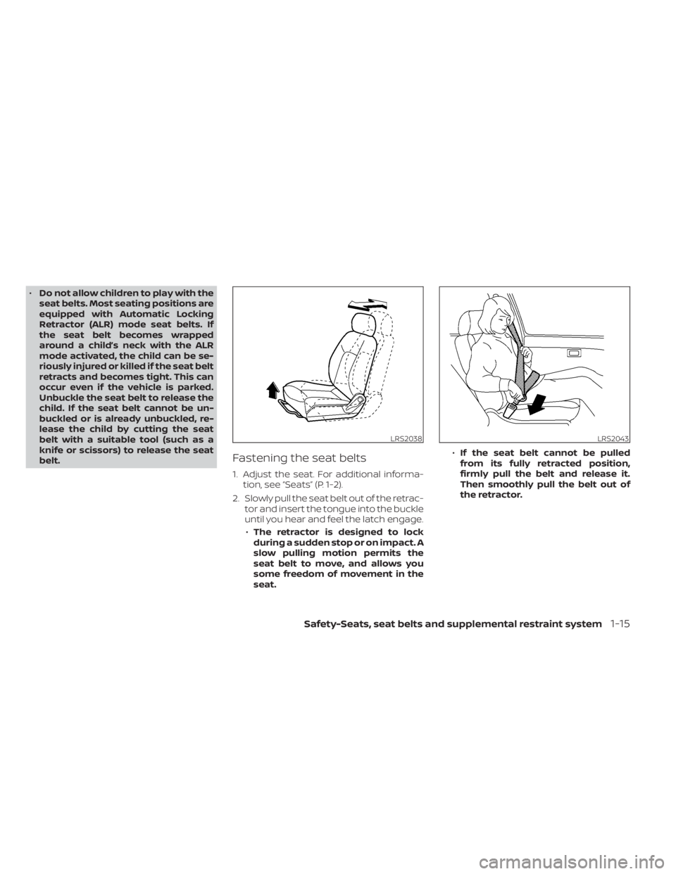
1. Adjust the seat. For additional informa- tion, see “Seats” (P. 1-2).
2. Slowly pull the seat belt out of the retrac- tor and insert the tongue into the buckle
until you hear and feel the latch engage.
• The retractor is designed to lock
during a sudden stop or on impact. A
slow pulling motion permits the
seat belt to move, and allows you
some freedom of movement in the
seat. •
If the seat belt cannot be pulled
from its fully retracted position,
firmly pull the belt and release it.
Then smoothly pull the belt out of
the retractor.
LRS2043
Page 39 of 300
WARNING
Do not allow children to play with the
seat belts. Most seating positions are
equipped with Automatic Locking Re-
tractor (ALR) mode seat belts. If the seat
belt becomes wrapped around a child’s
neck with the ALR mode activated, the
child can be seriously injured or killed if
the seat belt retracts and becomes
tight. This can occur even if the vehicle
is parked. Unbuckle the seat belt to re-
lease the child. If the seat belt cannot
be unbuckled or is already unbuckled,
release the child by cutting the seat
belt with a suitable tool (such as a knife
or scissors) to release the seat belt.
Children need adults to help protect
them. They need to be properly
restrained.
In addition to the general information in
this manual, child safety information is
available from many other sources, includ-
ing doctors, teachers, government traffic
safety offices, and community organiza-
tions. Every child is different, so be sure to
learn the best way to transport your child. There are three basic types of child re-
straint systems:
• Rear-facing child restraint
• Forward-facing child restraint
• Booster seat
Page 47 of 300
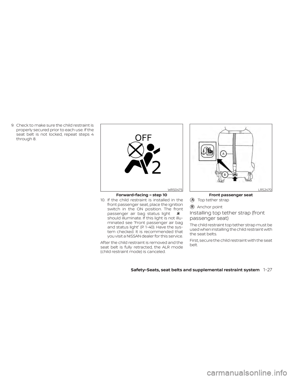
should illuminate. If this light is not illu-
minated see passenger air bag
and status lightŽ (P. 1-40). Have the sys-
tem checked. It is recommended that
you visit a NISSAN dealer for this service.
Af ter the child restraint is removed and the
seat belt is fully retracted, the ALR mode
(child restraint mode) is canceled.
Installing top tether strap (front
passenger seat)
The child restraint top tether strap must be
used when installing the child restraint with
the seat belts.
First, secure the child restraint with the seat
belt.
WRS0475
Forward-facing – step 10
Page 84 of 300
•When using a wheel without the
TPMS such as the spare tire, the TPMS
will not function and the low tire
pressure warning light will flash for
approximately 1 minute. The light will
remain on af ter 1 minute. Have your
tires replaced and/or TPMS system
reset as soon as possible. It is recom-
mended that you visit a NISSAN
dealer for these services.
• Replacing tires with those not origi-
nally specified by NISSAN could af-
fect the proper operation of the
TPMS.
CAUTION
• The TPMS is not a substitute for the
regular tire pressure check. Be sure
to check the tire pressure regularly.
• If the vehicle is being driven at
speeds of less than 16 mph (25 km/h),
the TPMS may not operate correctly.
• Be sure to install the specified size of
tires to the four wheels correctly.
Malfunction Indicator Light
(MIL)
If this indicator light comes on steady or
blinks while the engine is running, it may
indicate a potential emission control
malfunction.
The
may also come on steady if the
fuel-filler cap is loose or missing or if the
vehicle runs out of fuel. Check to make sure
the fuel-filler cap is installed and closed
tightly and that the vehicle has at least 3 gal
(11.4 L) of fuel in the fuel tank.
Af ter a few driving trips, the
light
should turn off if no other potential emis-
sion control system malfunction exists.
If this indicator light comes on steady for 20
seconds and then blinks for 10 seconds
when the engine is not running, it indicates
that the vehicle is not ready for an emission control system inspection/maintenance
test. For additional information, see “Readi-
ness for Inspection/Maintenance (I/M) test”
(P. 10-22).
Overdrive OFF indicator
light
The overdrive OFF indicator light illumi-
nates when the overdrive OFF mode is
selected.
For additional information, see “Continu-
ously Variable Transmission (CVT)” (P. 5-12).
Power steering warning
light
Page 134 of 300
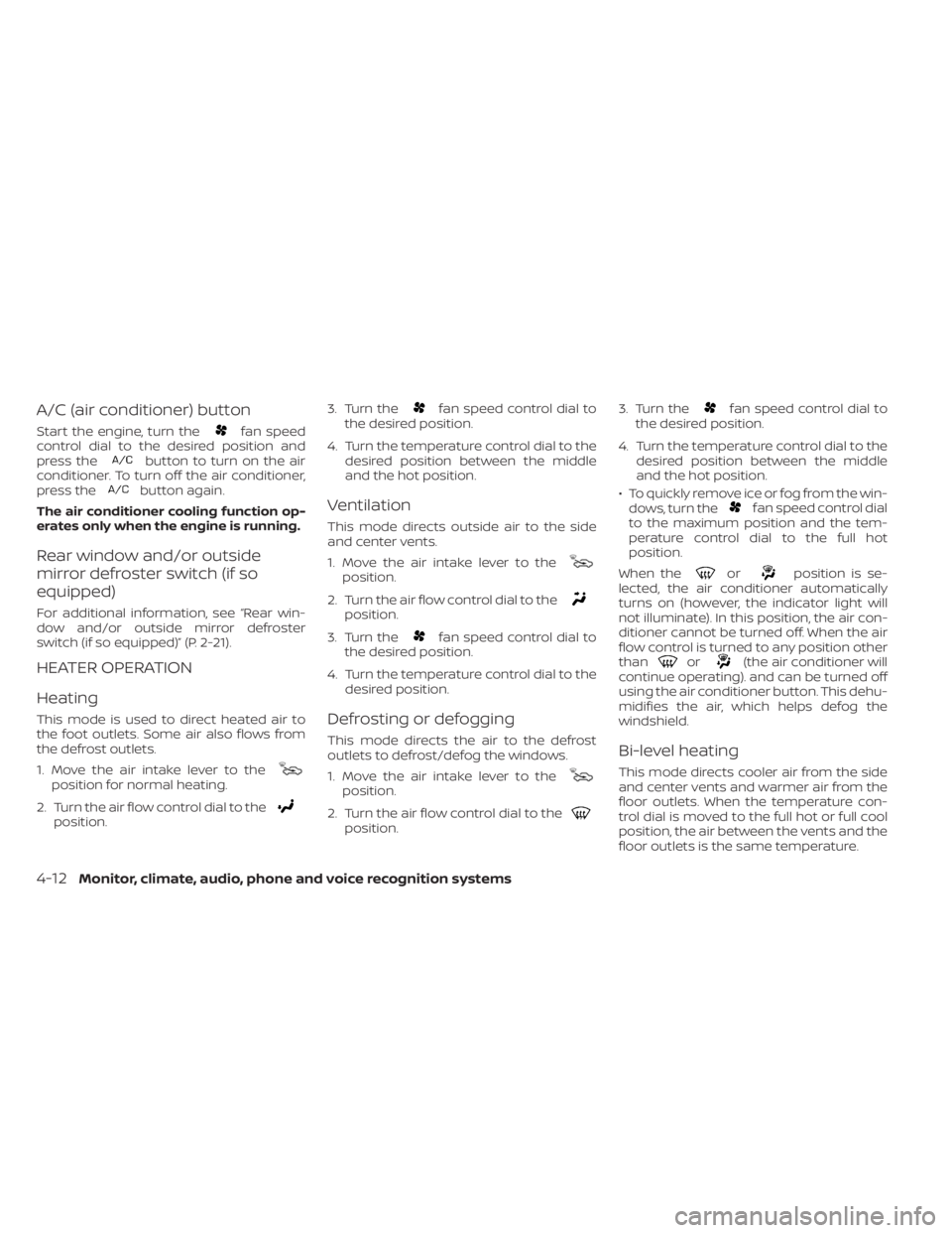
fan speed
control dial to the desired position and
press the
button to turn on the air
conditioner. To turn off the air conditioner,
press the
button again.
The air conditioner cooling function op-
erates only when the engine is running.
Rear window and/or outside
mirror defroster switch (if so
equipped)
For additional information, see “Rear win-
dow and/or outside mirror defroster
switch (if so equipped)” (P. 2-21).
HEATER OPERATION
Heating
This mode is used to direct heated air to
the foot outlets. Some air also flows from
the defrost outlets.
1. Move the air intake lever to the
position for normal heating.
2. Turn the air flow control dial to the
position. 3. Turn the
fan speed control dial to
the desired position.
4. Turn the temperature control dial to the desired position between the middle
and the hot position.
Ventilation
This mode directs outside air to the side
and center vents.
1. Move the air intake lever to the
position.
2. Turn the air flow control dial to the
position.
3. Turn the
fan speed control dial to
the desired position.
4. Turn the temperature control dial to the desired position.
Defrosting or defogging
This mode directs the air to the defrost
outlets to defrost/defog the windows.
1. Move the air intake lever to the
position.
2. Turn the air flow control dial to the
position. 3. Turn the
fan speed control dial to
the desired position.
4. Turn the temperature control dial to the desired position between the middle
and the hot position.
• To quickly remove ice or fog from the win- dows, turn the
fan speed control dial
to the maximum position and the tem-
perature control dial to the full hot
position.
When the
orposition is se-
lected, the air conditioner automatically
turns on (however, the indicator light will
not illuminate). In this position, the air con-
ditioner cannot be turned off. When the air
flow control is turned to any position other
than
or(the air conditioner will
continue operating). and can be turned off
using the air conditioner button. This dehu-
midifies the air, which helps defog the
windshield.
Bi-level heating
This mode directs cooler air from the side
and center vents and warmer air from the
floor outlets. When the temperature con-
trol dial is moved to the full hot or full cool
position, the air between the vents and the
floor outlets is the same temperature.
4-12Monitor, climate, audio, phone and voice recognition systems
Page 135 of 300
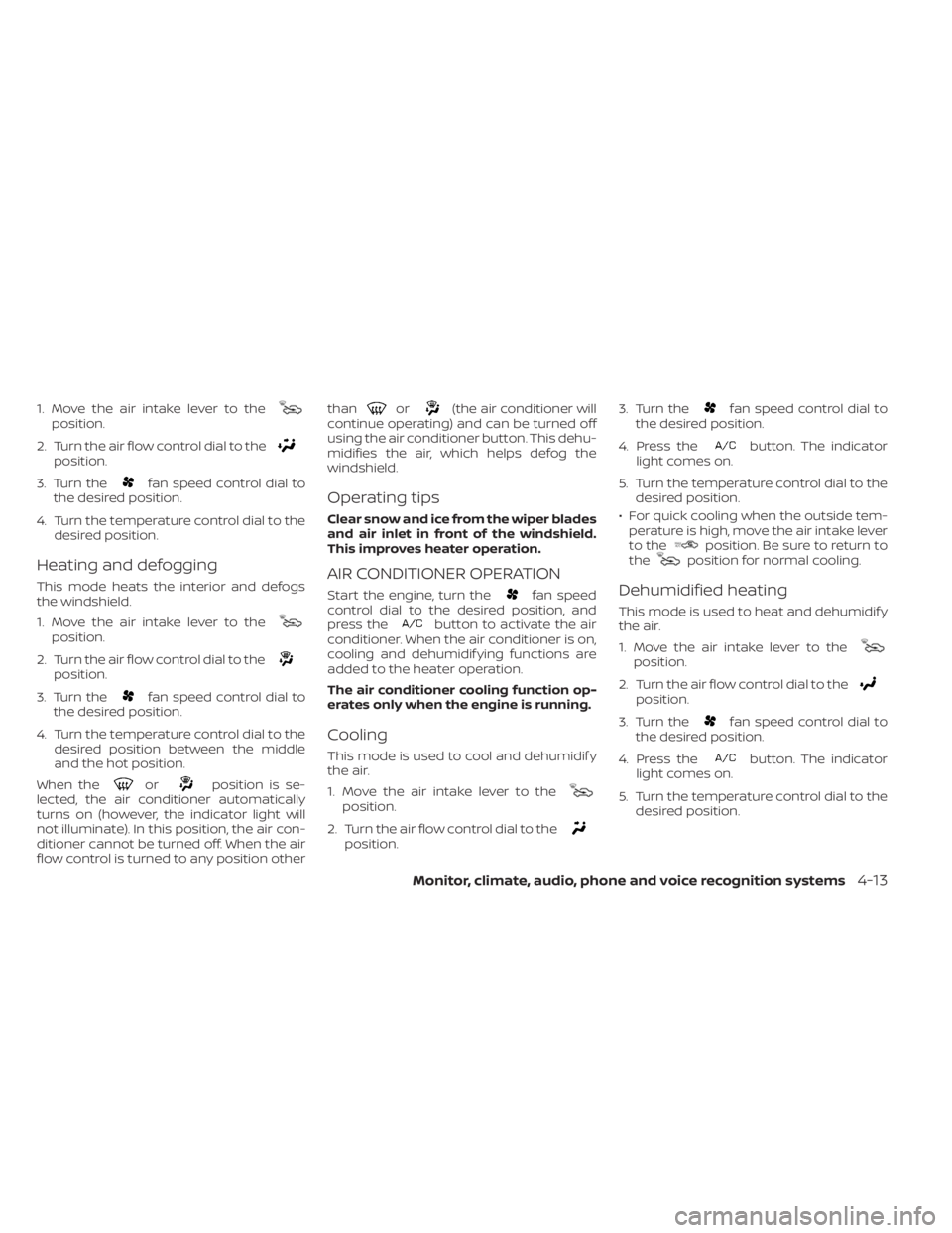
position.
2. Turn the air flow control dial to the
position.
3. Turn the
fan speed control dial to
the desired position.
4. Turn the temperature control dial to the desired position.
Heating and defogging
This mode heats the interior and defogs
the windshield.
1. Move the air intake lever to the
position.
2. Turn the air flow control dial to the
position.
3. Turn the
fan speed control dial to
the desired position.
4. Turn the temperature control dial to the desired position between the middle
and the hot position.
When the
orposition is se-
lected, the air conditioner automatically
turns on (however, the indicator light will
not illuminate). In this position, the air con-
ditioner cannot be turned off. When the air
flow control is turned to any position other than
or(the air conditioner will
continue operating) and can be turned off
using the air conditioner button. This dehu-
midifies the air, which helps defog the
windshield.
Operating tips
Clear snow and ice from the wiper blades
and air inlet in front of the windshield.
This improves heater operation.
AIR CONDITIONER OPERATION
Start the engine, turn thefan speed
control dial to the desired position, and
press the
button to activate the air
conditioner. When the air conditioner is on,
cooling and dehumidif ying functions are
added to the heater operation.
The air conditioner cooling function op-
erates only when the engine is running.
Cooling
This mode is used to cool and dehumidif y
the air.
1. Move the air intake lever to the
position.
2. Turn the air flow control dial to the
position. 3. Turn the
fan speed control dial to
the desired position.
4. Press the
button. The indicator
light comes on.
5. Turn the temperature control dial to the desired position.
• For quick cooling when the outside tem- perature is high, move the air intake lever
to the
position. Be sure to return to
theposition for normal cooling.
Dehumidified heating
This mode is used to heat and dehumidif y
the air.
1. Move the air intake lever to the
position.
2. Turn the air flow control dial to the
position.
3. Turn the
fan speed control dial to
the desired position.
4. Press the
button. The indicator
light comes on.
5. Turn the temperature control dial to the desired position.
Monitor, climate, audio, phone and voice recognition systems4-13
Page 153 of 300
ENGINE PROTECTION MODE
The engine has an engine protection mode
to reduce the chance of damage if the
coolant temperature becomes too high
(for example, when climbing steep grades
in high temperature with heavy loads, such
as when towing a trailer). When the engine
temperature reaches a certain level:
• The high temperature warning light willturn on.
• Engine power may be reduced.
• The air conditioning cooling function may be automatically turned off for a short
time (the blower will continue to operate).
Engine power and, under some conditions,
vehicle speed will decrease. Vehicle speed
can be controlled with the accelerator
pedal, but the vehicle may not accelerate at
the desired speed. The transmission will
downshif t or upshif t as it reaches pre-
scribed shif t points. You can also shif t
manually.
As driving conditions change and engine
coolant temperature is reduced, vehicle
speed can be increased using the accel-
erator pedal, and air conditioning cooling
function will automatically be turned back
on. Move the vehicle off the road in a safe area
and allow the engine to cool if the following
occurs:
1. The engine coolant temperature is not
reduced.
2. The air conditioning cooling function does not turn back on.
3. The engine oil pressure low and high temperature warning light
illumi-
nates. This may indicate a malfunction.
If af ter checking the oil and coolant, the
remains on, do not continue to drive. It
is recommended that you visit a NISSAN
dealer for servicing.
The Malfunction Indicator Light (MIL) may
also come ON. If onlyit remains on, you do
not need to have your vehicle towed, but
have it inspected soon. It is recommended
that you visit a NISSAN dealer for this ser-
vice. For additional information, see “Mal-
function Indicator Light (MIL)” (P. 2-14).
CAUTION
Running the engine with the engine oil
pressure warning light on could cause
serious damage to the engine almost
immediately. Such damage is not cov-
ered by warranty. Turn off the engine as
soon as it is safe to do so.
DRIVING THE VEHICLE
Starting and driving5-11
Page 158 of 300
Accelerator downshif t
— in D (Drive) position —
For passing or hill climbing, depress the
accelerator pedal to the floor. This shif ts
the transmission down into a lower gear,
depending on the vehicle speed.
High fluid temperature protection
mode
This transmission has a high fluid tem-
perature protection mode. If the fluid tem-
perature becomes too high (for example,
when climbing steep grades in high tem-
peratures with heavy loads, such as when
towing a trailer), engine power and, under
some conditions, vehicle speed will be de-
creased automatically to reduce the
chance of transmission damage. Vehicle
speed can be controlled with the accelera-
tor pedal, but the engine and vehicle speed
may be limited.
Fail-safe
When the fail-safe operation occurs, the
Continuously Variable Transmission will
not be shif ted into the selected driving
position.If the vehicle is driven under extreme
conditions, such as excessive wheel
spinning and subsequent hard braking,
the fail-safe system may be activated.
The Malfunction Indicator Light (MIL)
may come on to indicate the fail-safe
mode is activated. For additional infor-
mation, see “Malfunction Indicator Light
(MIL)” (P. 2-14). This will occur even if all
electrical circuits are functioning prop-
erly. In this case, place the ignition switch
in the OFF position and wait for 10 sec-
onds. Then place the ignition switch
back in the ON position. The vehicle
should return to its normal operating
condition. If it does not return to its nor-
mal operating condition, have the trans-
mission checked and repaired, if neces-
sary. It is recommended that you visit a
NISSAN dealer for this service.
WARNING
When the high fluid temperature pro-
tection mode or fail-safe operation oc-
curs, vehicle speed may be gradually
reduced. The reduced speed may be
lower than other traffic, which could in-
crease the chance of a collision. Be es-
pecially careful when driving. If neces-
sary, pull to the side of the road at a safe
place and allow the transmission to re-
turn to normal operation, or have it re-
paired if necessary.
5-16Starting and driving