Page 65 of 300

•Tampering with the front air bag sys-
tem may result in serious personal
injury. Tampering includes changes
to the steering wheel and the instru-
ment panel assembly by placing ma-
terial over the steering wheel pad
and above the instrument panel or
by installing additional trim material
around the air bag system.
• Removing or modif ying the front
passenger seat may affect the func-
tion of the air bag system and result
in serious personal injury.
• Modif ying or tampering with the
front passenger seat may result in
serious personal injury. For example,
do not change the front seats by
placing material on the seat cushion
or by installing additional trim mate-
rial, such as seat covers, on the seat
that are not specifically designed to
assure proper air bag operation. Ad-
ditionally, do not stow any objects
under the front passenger seat or the
seat cushion and seatback. Such ob-
jects may interfere with the proper
operation of the occupant classifica-
tion sensor (weight sensor). •
No unauthorized changes should be
made to any components or wiring
of the seat belt system. This may af-
fect the front air bag system. Tam-
pering with the seat belt system may
result in serious personal injury.
• It is recommended that you visit a
NISSAN dealer for work on and
around the front air bag. It is also rec-
ommended that you visit a NISSAN
dealer for installation of electrical
equipment. The Supplemental Re-
straint System (SRS) wiring har-
nesses* should not be modified or
disconnected. Unauthorized electri-
cal test equipment and probing de-
vices should not be used on the air
bag system.
• A cracked windshield should be re-
placed immediately by a qualified re-
pair facility. A cracked windshield
could affect the function of the
supplemental air bag system.
*The SRS wiring harness connectors are
yellow and orange for easy
identification. When selling your vehicle, we request that
you inform the buyer about the front air
bag system and guide the buyer to the
appropriate sections in this Owner's
Manual.
Safety-Seats, seat belts and supplemental restraint system1-45
Page 69 of 300
SUPPLEMENTAL AIR BAG WARNING
LIGHT
The supplemental air bag warning light,
displayingin the instrument panel,
monitors the circuits for the air bag sys-
tems, pretensioner(s) and all related wiring.
When the ignition switch is placed in the ON
position, the supplemental air bag warning
light illuminates for about 7 seconds and
then turns off. This means the system is
operational. If any of the following conditions occur, the
front air bag, side air bag, curtain air bag
and pretensioner systems need servicing:
• The supplemental air bag warning light
remains on af ter approximately 7
seconds.
• The supplemental air bag warning light flashes intermittently.
• The supplemental air bag warning light does not come on at all.
Under these conditions, the front air bag,
side air bag, curtain air bag or pretensioner
systems may not operate properly. They
must be checked and repaired. It is recom-
mended that you visit a NISSAN dealer for
this service.
LRS0100
Page 91 of 300
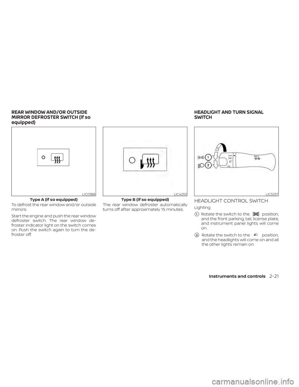
position,
and the front parking, tail, license plate,
and instrument panel lights will come
on.
�2Rotate the switch to theposition,
and the headlights will come on and all
the other lights remain on.
LIC0388
Type A (if so equipped)
Instruments and controls2-21
Page 93 of 300
WARNING
When the DRL system is active, tail
lights on your vehicle are not on. It is
necessary at dusk to turn on your
headlights. Failure to do so could cause
an accident injuring yourself and
others.
INSTRUMENT BRIGHTNESS
CONTROL
The instrument brightness control oper-
ates when the headlight control switch is in
the
orposition.
Push the control
OAto adjust the bright-
ness of the instrument panel lights.
TURN SIGNAL SWITCH
Turn signal
Move the lever up or down to signal the
turning direction. When the turn is com-
pleted, the turn signals cancel
automatically.
LIC2289LIC2473
Page 97 of 300
FRONT-DOOR POCKETS
UNDER-SEAT STORAGE BIN
To open the drawer, lif t up slightly and pull
to open. To remove the drawer, pull to the
point of resistance and lif t up and pull.
LIC2450LIC3653
Instrument panel
STORAGE
Instruments and controls2-27
Page 117 of 300
1. Pull the hood lock release handleOElo-
cated below the instrument panel until
the hood springs up slightly.
2. Locate the lever
OAin between the hood
and grille and push the lever sideways
with your fingertips.
3. Raise the hood
OB.
4. Remove the support rod
OCand insert it
into the slot
OD. Hold the coated parts of the support rod
when removing or resetting the support
rod. Avoid direct contact with the metal
parts, as they may be hot immediately
af ter the engine has been stopped.
When closing the hood, return the support
rod to its original position, lower the hood
to approximately 12 in (30 cm) above the
latch and release it. This allows proper en-
gagement of the hood latch.
Pre-driving checks and adjustments3-13
Page 118 of 300
OPENER OPERATION
The fuel-filler door release is located below
the instrument panel. To open the fuel-filler
door, pull the release. To lock, close the fuel-
filler door securely.
FUEL-FILLER CAP
Malfunc-
tion Indicator Light (MIL) to come on.
• Never pour fuel into the throttle body
to attempt to start your vehicle. •
Do not fill a portable fuel container in
the vehicle or trailer. Static electricity
can cause an explosion of flammable
liquid, vapor or gas in any vehicle or
trailer. To reduce the risk of serious
injury or death when filling portable
fuel containers:
– Always place the container on the
ground when filling.
– Do not use electronic devices
when filling.
– Keep the pump nozzle in contact
with the container while you are
filling it.
– Use only approved portable fuel
containers for flammable liquid.
CAUTION
• Do not use E-15 or E-85 in your ve-
hicle. For additional information, see
“Fuel Recommendation” (P. 10-3).
Page 157 of 300
indicator light in the instrument panel
illuminates. For additional information, see
OFF indicator lightŽ (P. 2-14).
Use the overdrive OFF mode when you
need improved engine braking.
To turn off the overdrive OFF mode, push
the O/D OFF switch again. The
indi-
cator light will turn off.
Each time the engine is started, or when
the shif t lever is moved to any position
other than D (Drive), the overdrive OFF
mode will be automatically turned off.
LSD2141LSD2140
 and all related wiring.
W")


.
Use the overdrive OFF mode when you
need improved engine braking.
To turn off the")