Page 194 of 508
•The Loose Fuel Cap warning mes-
sage will appear if the fuel-filler cap
is not properly tightened. It may take
a few driving trips for the message to
be displayed. Failure to tighten the
fuel-filler cap properly af ter the
Loose Fuel Cap warning message ap-
pears may cause the
Malfunc-
tion Indicator Light (MIL) to
illuminate.
• Failure to tighten the fuel-filler cap
properly may cause the
Mal-
function Indicator Light (MIL) to illu-
minate. If the
light illuminates
because the fuel-filler cap is loose or
missing, tighten or install the cap and
continue to drive the vehicle. The
light should turn off af ter a few
driving trips. If thelight does not
turn off af ter a few driving trips, have
the vehicle inspected. It is recom-
mended that you visit a NISSAN
dealer for this service.
• For additional information, see “Mal-
function Indicator Light (MIL)”
(P. 2-13).
• If fuel is spilled on the vehicle body,
flush it away with water to avoid
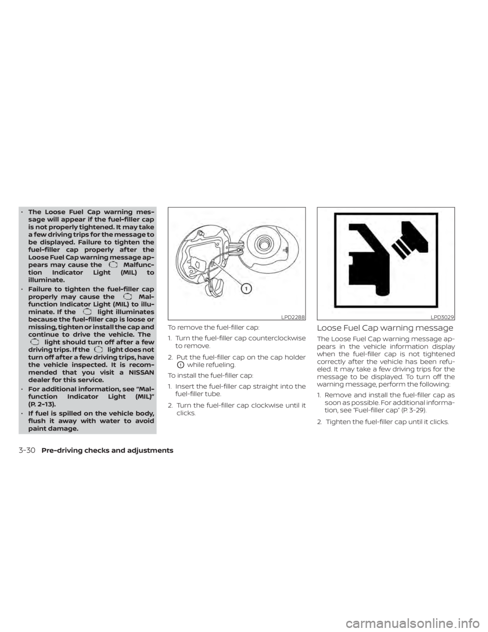
paint damage. To remove the fuel-filler cap:
1. Turn the fuel-filler cap counterclockwise
to remove.
2. Put the fuel-filler cap on the cap holder
O1while refueling.
To install the fuel-filler cap:
1. Insert the fuel-filler cap straight into the fuel-filler tube.
2. Turn the fuel-filler cap clockwise until it clicks.
Loose Fuel Cap warning message
The Loose Fuel Cap warning message ap-
pears in the vehicle information display
when the fuel-filler cap is not tightened
correctly af ter the vehicle has been refu-
eled. It may take a few driving trips for the
message to be displayed. To turn off the
warning message, perform the following:
1. Remove and install the fuel-filler cap assoon as possible. For additional informa-
tion, see “Fuel-filler cap” (P. 3-29).
2. Tighten the fuel-filler cap until it clicks.
LPD2288LPD3029
3-30Pre-driving checks and adjustments
Page 198 of 508
CARD HOLDER
To use the card holder, slide card into the
clip. Do not view information while operat-
ing the vehicle.
MANUAL ANTI-GLARE REARVIEW
MIRROR (if so equipped)
Use the night positionO1to reduce glare
from the headlights of vehicles behind you
at night.
Use the day position
O2when driving in
daylight hours.
Page 199 of 508
Type A (if so equipped)
The inside mirror is designed so that it au-
tomatically dims during night time condi-
tions and according to the intensity of the
headlights of the vehicle following you. The
automatic anti-glare feature is activated
when the ignition switch is in the ON
position.
Type B (if so equipped)
The indicator lightO2will illuminate when
the automatic anti-glare feature is operat-
ing.
• To turn off the automatic anti-glare fea- ture, press the O button. The indicator
light will turn off.
• To turn on the automatic anti-glare fea- ture, press the | button again. The in-
dicator light will turn on.
For additional information on HomeLink®
Universal Transceiver operation, see
“HomeLink® Universal Transceiver” (P. 2-66).
OUTSIDE MIRRORS
LPD0469
Page 213 of 508
•When washing the vehicle with high
pressure water, be sure not to spray it
around the camera. Otherwise, water
may enter the camera unit causing
water condensation on the lens, a
malfunction, fire or an electric shock.
• Do not strike the camera. It is a preci-
sion instrument. Otherwise, it may
malfunction or cause damage result-
ing in a fire or an electric shock.
The following are operating limitations and
do not represent a system malfunction:
• When the temperature is extremely high or low, the screen may not clearly display
objects.
• When strong light directly shines on the camera, objects may not be displayed
clearly.
• Vertical lines may be seen in objects on the screen. This is due to strong reflected
light from the bumper.
• The screen may flicker under fluorescent light.
• The colors of objects on the RearView Monitor may differ somewhat from the
actual color of objects.
• Objects on the monitor may not be clear in a dark environment. • There may be a delay when switching
between views.
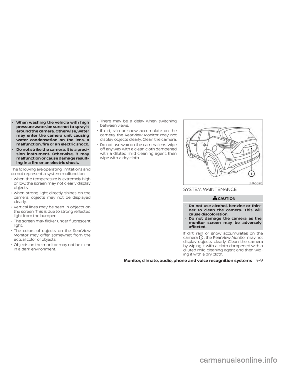
• If dirt, rain or snow accumulate on the camera, the RearView Monitor may not
display objects clearly. Clean the camera.
• Do not use wax on the camera lens. Wipe off any wax with a clean cloth dampened
with a diluted mild cleaning agent, then
wipe with a dry cloth.
SYSTEM MAINTENANCE
LHA3828
Page 218 of 508
Bird’s-eye view
The bird's-eye view shows the overhead
view of the vehicle, which helps confirm the
vehicle position and the predicted course
to a parking space.
The vehicle icon
O1shows the position of
the vehicle. Note that the apparent dis-
tance between objects viewed in the
bird's-eye view may differ somewhat from
the actual distance to the vehicle.
The areas that the cameras cannot cover
O2are indicated in black. Af ter the ignition switched is placed in the
ON position, the non-viewable area
O2is
highlighted in yellow for 3 seconds af ter the
birds-eye view is displayed.
In addition, the non-viewable corners (if so
equipped) are displayed in red and will blink
for the first 3 seconds
O3to remind the
driver to be cautious.
LHA4264LHA2652
4-14Monitor, climate, audio, phone and voice recognition systems
Page 233 of 508
front defroster button on.
The indicator light on the button will
come on.
2. Turn the temperature control dial to set the maximum temperature to aid in de-
frosting or defogging.
• To quickly remove ice from the outside of the windows, use the
fan speed con-
trol buttons to set the fan speed to
maximum. • As soon as possible af ter the windshield
is clean, press the AUTO button to return
to the automatic mode.
•
When thefront defroster button is
pressed, the air conditioner will automati-
cally be turned on at outside temperatures
above 36°F (2°C). The air recirculate mode
automatically turns off, allowing outside air
to be drawn into the passenger compart-
ment to further improve the defogging
performance. When the air recirculate
mode automatically turns off, the air fresh
mode will automatically turn on.
Remote Engine Start with
Intelligent Climate Control (if so
equipped)
Vehicles equipped with automatic climate
controls and Remote Engine Start function
may go into automatic heating or cooling
mode when Remote Engine Start is acti-
vated depending on outside and cabin
temperatures. During this period, the cli-
mate control display and buttons will be
inoperable until the ignition switch is
turned on. In Remote Engine Start defrost-
ing mode, the rear window defroster,
heated seats (if so equipped) and heated
steering wheel (if so equipped) may be ac-
tivated automatically.
Monitor, climate, audio, phone and voice recognition systems4-29
Page 234 of 508
fan speed control buttons
to manually control the fan speed.
Press the AUTO button to return to auto-
matic control of the fan speed.
Temperature control dial
The temperature control dial allows you to
adjust the temperature of the outlet air. To
lower the temperature, turn the dial to the
lef t. To increase the temperature, turn the
dial to the right. Temperature can be ad-
justed on the driver’s and passenger’s side.
Air recirculation
Press theair recirculation button to
recirculate interior air inside the vehicle.
The
indicator light on the button will
come on.
The air recirculation cannot be activated
when the air conditioner is in the
front
defrosting mode. When the outside temperature exceeds
70°F (21°C), the air conditioning system may
default to air recirculation mode automati-
cally to reduce overall power consumption.
To exit air recirculation mode, select the
fresh air intake button to enter fresh air
mode.
Fresh air intake
Press thefresh air intake button to
draw outside air into the passenger
compartment.
A/C (air conditioner) button
Start the engine, press thefan speed
control buttons to the desired position and
press the
button to turn on the air
conditioner. To turn off the air conditioner,
press the
button again.
The air conditioner cooling function op-
erates only when the engine is running.
Air flow control
Pressing the MODE button manually con-
trols air flow and selects the air outlet:
— Air flows mainly from center and side vents.
— Air flows mainly from center andside vents and foot outlets.
— Air flows mainly from foot outletsand partly from defroster.
— Air flows mainly from defrosterand foot outlets.
To turn system off
Press the ON-OFF button.
Rear window and outside mirror
(if so equipped) defroster switch
For additional information, see “Rear win-
dow and outside mirror (if so equipped)
defroster switch” (P. 2-34).
4-30Monitor, climate, audio, phone and voice recognition systems
Page 237 of 508
CAUTION
• Keep the antenna as far away as pos-
sible from the electronic control
modules.
• Keep the antenna wire more than 8 in
(20 cm) away from the electronic
control system harnesses. Do not
route the antenna wire next to any
harness.
• Adjust the antenna standing-wave
ratio as recommended by the
manufacturer.
• Connect the ground wire from the CB
radio chassis to the body.
• For additional information, it is rec-
ommended that you visit a NISSAN
dealer for servicing. “Made for iPod”, “Made for iPhone” and
“Made for iPad” mean that an electronic
accessory has been designed to connect
specifically to iPod, iPhone or iPad, respec-
tively, and has been certified by the devel-
oper to meet Apple performance stan-
dards. Apple is not responsible for the
operation of this device or its compliance
with safety and regulatory standards.
Please note that the use of this accessory
with iPod, iPhone or iPad may affect wire-
less performance.
iPad, iPhone, iPod classic, iPod nano, iPod
shuffle and iPod touch are trademarks of
Apple Inc., registered in the U.S. and other
countries. Lightning is a trademark of
Apple Inc.
iPod®/IPHONE®
Monitor, climate, audio, phone and voice recognition systems4-33