Page 97 of 508
Odometer/Twin trip odometer
The odometer and the twin trip odometer
O1are displayed in the vehicle information
display when the ignition switch is placed
in the ON position.
The odometer records the total distance
the vehicle has been driven.
The twin trip odometer records the dis-
tance of individual trips.
Changing the display
Push the TRIP RESET switchO2on the lef t
side of the instrument panel to change the
display as follows:
Trip
LIC3780
Page 110 of 508

— go back or forward
through the vehicle information menu
items or to change from one display
screen to the next (i.e. trip, TPMS, fuel
economy).
The OK and
buttons also
control audio and control panel functions
in some conditions. Most screens and
menus offer instruction prompts of the
steering switch buttons to indicate how to
control the vehicle information display. An
orange cursor is shown to indicate where
you are in the available menu items. A scroll
bar with up and down arrows will appear if
there is more than one page of menu
items. For additional information, refer to
the separate NissanConnect® Owner’s
Manual.
STARTUP DISPLAY
When the vehicle in placed in the ON or ACC
position the screens that display in the ve-
hicle information display include:
• Home
• Audio
• Navigation (if so equipped)
• Drive computer
• Fuel economy
• Driving aids (if so equipped)
• Speed Limit Sign (if so equipped)
• Tire pressure information
• Warning review
• Settings
The warnings review title screen will show
how many active warnings exist, or “No
items to review” in the event that no warn-
ings are active. For additional information
on warnings and indicators, see “Vehicle
information display warnings and indica-
tors” (P. 2-24).
To control what items display in the vehicle
information display, see “Customize Dis-
play ” (P. 2-20).
SETTINGS
The setting mode allows you to change the
information displayed in the vehicle infor-
mation display:
• Driver Assistance
• Customize Display
• Vehicle Settings
• Maintenance
• Clock
• TPMS Settings
• Unit / Language
• Key-Linked Settings
• Factory Reset
2-18Instruments and controls
Page 127 of 508
NOTE:
The top and bottom few rows of wires on
the rear window are not part of the rear
window defroster system. These wires
make up the antenna for the audio
system.
HEADLIGHT CONTROL SWITCH
Lighting
�1Rotate the switch to theposition,
and the front parking, tail, license plate,
and instrument panel lights will come
on.
�2Rotate the switch to theposition,
and the headlights will come on and all
the other lights remain on.
Instruments and controls2-35
Page 129 of 508
,orposition.Be sure you do not put anything on top
of the autolight sensor located in the top
side
O1of the instrument panel. The au-
tolight sensor controls the autolight; if it
is covered, the autolight sensor reacts as
if it is dark out and the headlights will
illuminate. If this occurs while parked
with the engine off and the ignition
switch placed in the ON position, your
vehicle's battery could become
discharged.
Headlight beam select
�1To select the high beam function, push
the lever forward while the low beams
are on. The high beam lights come on
and the
indicator light illuminates.
�2Pull the lever back to return to the low
beams.
�3Pulling and releasing the lever flashes
the headlight high beams on and off.
The low beams do not need to be on
for this to function.
LIC2237LIC3250
Page 143 of 508
•Do not use double adapters or more
than one electrical accessory.
• Use power outlets with the engine
running to avoid discharging the ve-
hicle battery.
• Avoid using power outlets when the
air conditioner, headlights or rear
window defroster is on.
• Before inserting or disconnecting a
plug, be sure the electrical accessory
being used is turned off.
• Push the plug in as far as it will go. If
good contact is not made, the plug
may overheat or the internal tem-
perature fuse may open.
• When not in use, be sure to close the
cap. Do not allow water or any other
liquid to contact the outlet. The extended storage switch is pulled out
when in transit from the factory to the re-
tailer. It is located in the fuse panel to the
lef t of the steering wheel on the instrument
panel. If any electrical equipment does not
operate, ensure the extended storage
switch is pushed fully in place, as shown.
LIC4599LIC3266
Pulled position
EXTENDED STORAGE SWITCH
Instruments and controls2-51
Page 175 of 508

CAUTION
• When locking the doors using the re-
quest switch, make sure to have the
Intelligent Key in your possession
before operating the request switch
to prevent the Intelligent Key from
being lef t in the vehicle.
• The request switch is operational
only when the Intelligent Key has
been detected by the Intelligent Key
system.
Lockout protection
To prevent the Intelligent Key from being
accidentally locked in the vehicle, lockout
protection is equipped with the Intelligent
Key.
When the driver’s side door is open, the
doors are locked, then the Intelligent Key is
lef t inside the vehicle and the door is
closed, all doors will unlock automatically.
NOTE:
The doors may not lock when the Intelli-
gent Key is in the same hand that is op-
erating the request switch to lock the
door. Put the Intelligent Key in a purse,
pocket or your other hand.
CAUTION
The lockout protection may not func-
tion under the following conditions:
• When the Intelligent Key is placed on
top of the instrument panel.
• When the Intelligent Key is placed in-
side the glove box or a storage bin.
• When the Intelligent Key is placed in-
side the door pockets.
• When the Intelligent Key is placed in-
side or near metallic materials.
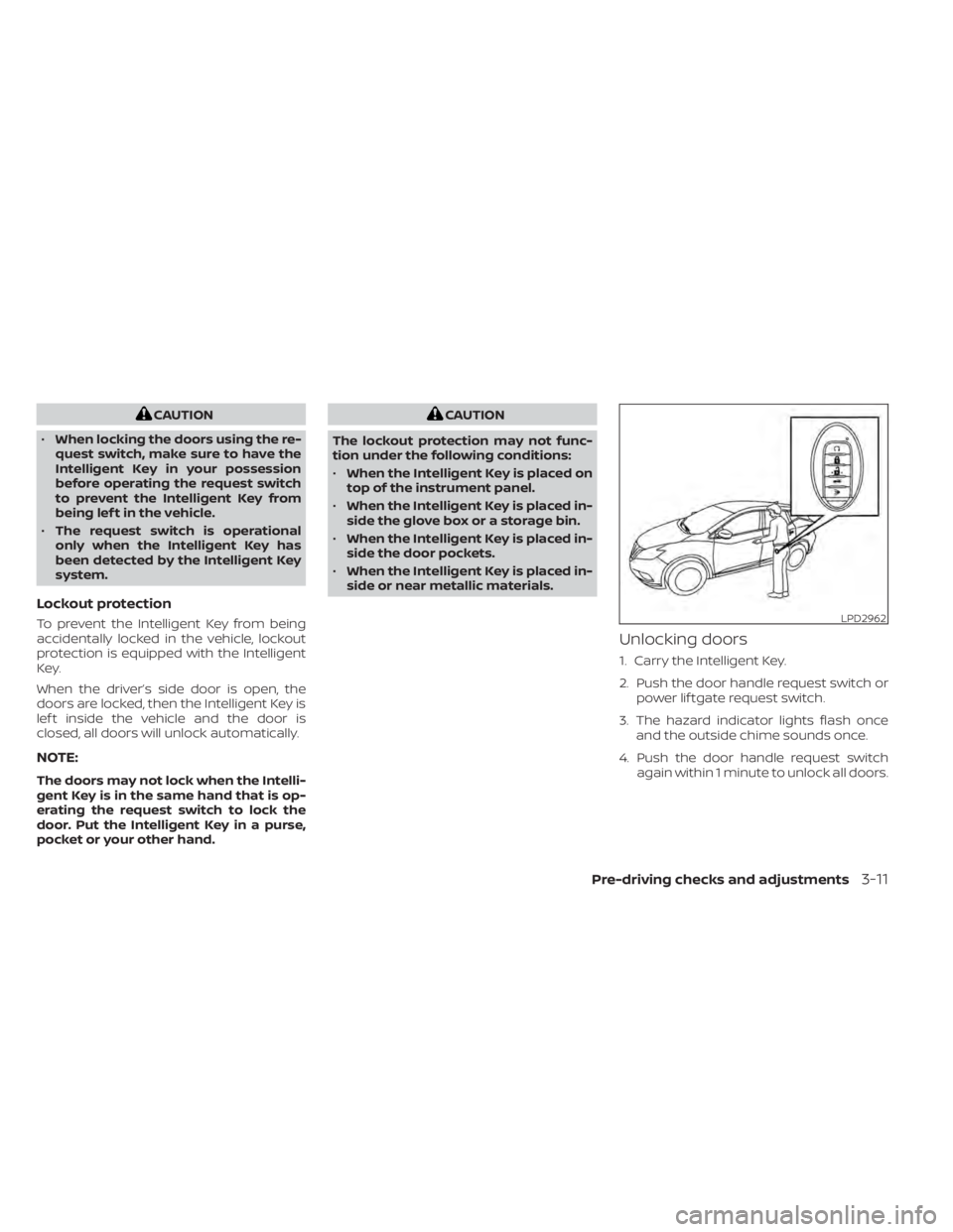
Unlocking doors
1. Carry the Intelligent Key.
2. Push the door handle request switch or power lif tgate request switch.
3. The hazard indicator lights flash once and the outside chime sounds once.
4. Push the door handle request switch again within 1 minute to unlock all doors.
LPD2962
Page 185 of 508

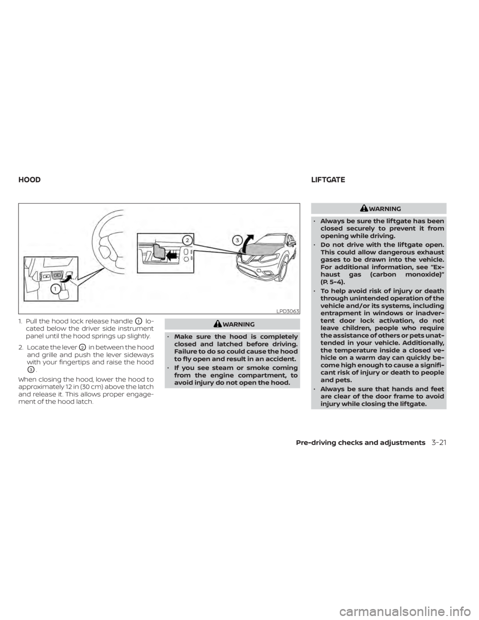
1. Pull the hood lock release handleO1lo-
cated below the driver side instrument
panel until the hood springs up slightly.
2. Locate the lever
O2in between the hood
and grille and push the lever sideways
with your fingertips and raise the hood
O3.
When closing the hood, lower the hood to
approximately 12 in (30 cm) above the latch
and release it. This allows proper engage-
ment of the hood latch.
WARNING
• Always be sure the lif tgate has been
closed securely to prevent it from
opening while driving.
• Do not drive with the lif tgate open.
This could allow dangerous exhaust
gases to be drawn into the vehicle.
For additional information, see “Ex-
haust gas (carbon monoxide)”
(P. 5-4).
• To help avoid risk of injury or death
through unintended operation of the
vehicle and/or its systems, including
entrapment in windows or inadver-
tent door lock activation, do not
leave children, people who require
the assistance of others or pets unat-
tended in your vehicle. Additionally,
the temperature inside a closed ve-
hicle on a warm day can quickly be-
come high enough to cause a signifi-
cant risk of injury or death to people
and pets.
• Always be sure that hands and feet
are clear of the door frame to avoid
injury while closing the lif tgate.
Pre-driving checks and adjustments3-21
Page 186 of 508
CAUTION
Do not use accessory carriers that at-
tach to the lif tgate. Doing so will cause
damage to the vehicle.
OPERATING THE MANUAL
LIFTGATE (if so equipped)
The power door lock system allows you to
lock or unlock all doors including the lif t-
gate simultaneously.
To open the lif tgate, push the lif tgate
opener switch
OAand pull up on the
handle.
To close, lower and push the lif tgate down
securely.
OPERATING THE POWER LIFTGATE
(if so equipped)
LPD2212
Instrument panel switch