Page 142 of 618

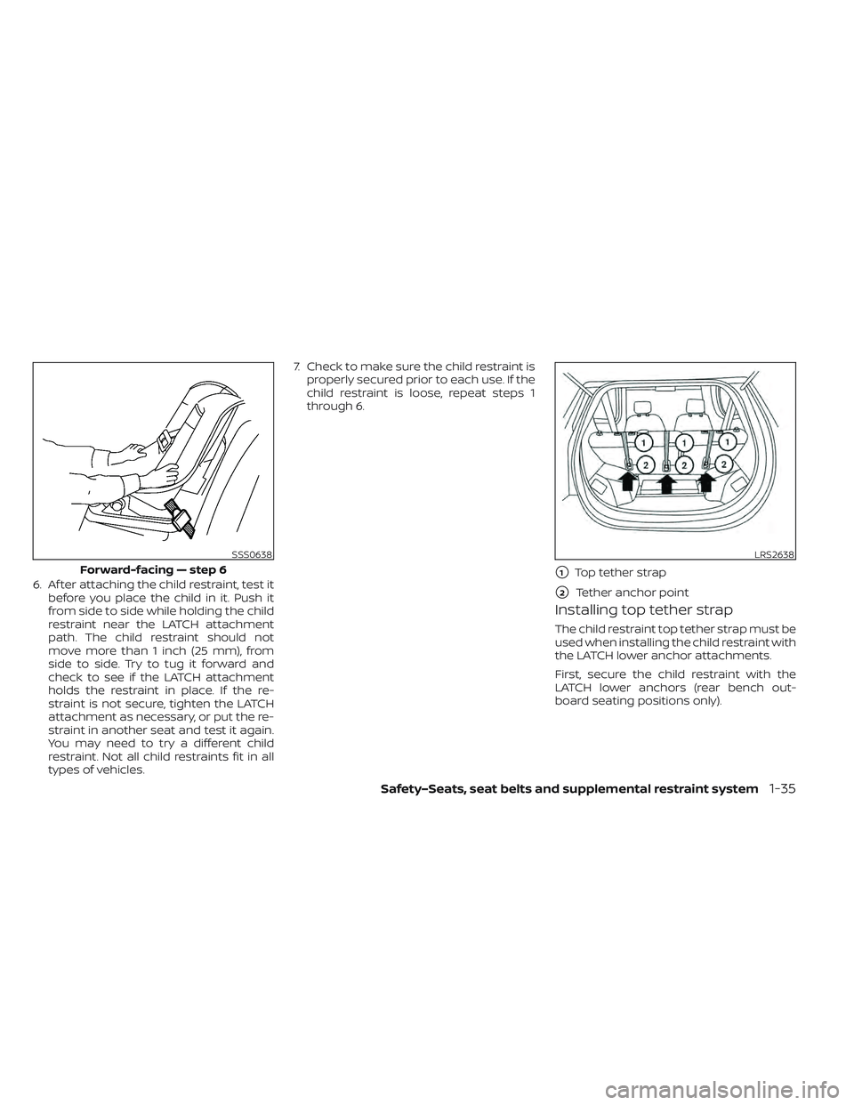
6. Af ter attaching the child restraint, test itbefore you place the child in it. Push it
from side to side while holding the child
restraint near the LATCH attachment
path. The child restraint should not
move more than 1 inch (25 mm), from
side to side. Try to tug it forward and
check to see if the LATCH attachment
holds the restraint in place. If the re-
straint is not secure, tighten the LATCH
attachment as necessary, or put the re-
straint in another seat and test it again.
You may need to try a different child
restraint. Not all child restraints fit in all
types of vehicles. 7. Check to make sure the child restraint is
properly secured prior to each use. If the
child restraint is loose, repeat steps 1
through 6.
Installing top tether strap
The child restraint top tether strap must be
used when installing the child restraint with
the LATCH lower anchor attachments.
First, secure the child restraint with the
LATCH lower anchors (rear bench out-
board seating positions only).
SSS0638
Forward-facing — step 6
LRS2638
�1Top tether strap
�2Tether anchor point
Safety–Seats, seat belts and supplemental restraint system1-35
Page 145 of 618
3. Route the seat belt tongue through thechild restraint and insert it into the
buckle until you hear and feel the latch
engage. Be sure to follow the child re-
straint manufacturer’s instructions for
belt routing.
If the child restraint is equipped with a
top tether strap, route the top tether
strap and secure the tether strap to the
tether anchor point (rear seat installa-
tion only). For additional information, see
“Installing top tether strap” (P. 1-40). Do not install child restraints that require
the use of a top tether strap in seating
positions that do not have a top tether
anchor.
4. Pull the shoulder belt until the belt is fullyextended. At this time, the seat belt re-
tractor is in the ALR mode (child restraint
mode). It reverts to the ELR mode when
the seat belt is fully retracted.
SSS0360B
Forward-facing — step 3
SSS0651
Forward-facing — step 4
1-38Safety–Seats, seat belts and supplemental restraint system
Page 231 of 618
WARNING
When the LED DRL system is active, tail
lights on your vehicle are not on. It is
necessary at dusk to turn on your
headlights. Failure to do so could cause
an accident injuring yourself and
others.
INSTRUMENT BRIGHTNESS
CONTROL
Press the “+” button to increase the bright-
ness of the instrument panel lights.
Press the “-” to decrease the brightness of
the instrument panel lights.
TURN SIGNAL SWITCH
Turn signal
O1Move the lever up or down until it
latches to signal the turning direction.
When the turn is completed, the turn signal
cancels automatically.
Lane change signal
O2Move the lever up or down until the turn
signal begins to flash, but the lever does
not latch, to signal a lane change. Hold the
lever until the lane change is completed.
LIC3801SIC3671
2-54Instruments and controls
Page 232 of 618
Move the lever up or down until the turn
signal begins to flash, but the lever does
not latch, and release the lever. The turn
signal will automatically flash three times.
Choose the appropriate method to signal
a lane change based on road and traffic
conditions.To turn the fog lights on, rotate the head-
light switch to the
position, then ro-
tate the switch to theposition. To turn
them off, rotate the switch to the OFF
position.
The headlights must be on for the fog
lights to operate. To sound the horn, push the center pad
area of the steering wheel.
WARNING
Do not disassemble the horn. Doing so
could affect proper operation of the
supplemental front air bag system.
Tampering with the supplemental
front air bag system may result in seri-
ous personal injury.
SIC3672LIC3805
FOG LIGHT SWITCH (if so equipped) HORN
Instruments and controls2-55
Page 240 of 618
STORAGE TRAY
WARNING
Do not place sharp objects in the tray(s)
to help prevent injury in an accident or
sudden stop.
GLOVE BOX
To open the glove box, pull the handle.
To close, push the lid in until it latches.
WARNING
Keep the glove box lid closed while
driving to prevent injury in case of an
accident or a sudden stop.
CONSOLE BOX
To open the console box, pull up the lever
and pull up the lid. To close, push the lid
down until it is latched.
LIC4292
Instrument panel
LIC4349LIC3813
Instruments and controls2-63
Page 271 of 618

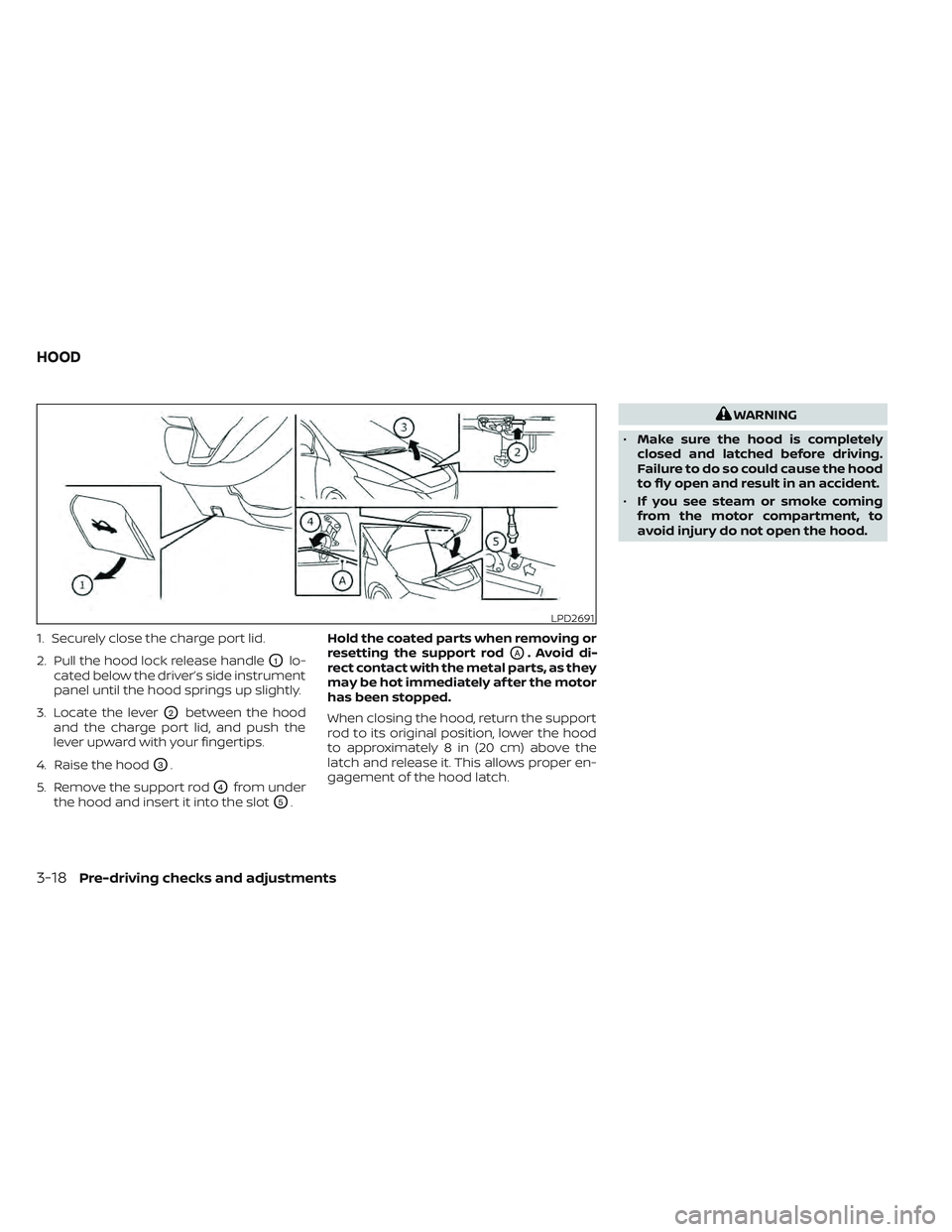
1. Securely close the charge port lid.
2. Pull the hood lock release handle
O1lo-
cated below the driver’s side instrument
panel until the hood springs up slightly.
3. Locate the lever
O2between the hood
and the charge port lid, and push the
lever upward with your fingertips.
4. Raise the hood
O3.
5. Remove the support rod
O4from under
the hood and insert it into the slot
O5. Hold the coated parts when removing or
resetting the support rod
OA. Avoid di-
rect contact with the metal parts, as they
may be hot immediately af ter the motor
has been stopped.
When closing the hood, return the support
rod to its original position, lower the hood
to approximately 8 in (20 cm) above the
latch and release it. This allows proper en-
gagement of the hood latch.
WARNING
• Make sure the hood is completely
closed and latched before driving.
Failure to do so could cause the hood
to fly open and result in an accident.
• If you see steam or smoke coming
from the motor compartment, to
avoid injury do not open the hood.
LPD2691
HOOD
3-18Pre-driving checks and adjustments
Page 274 of 618
When opening the charge port lid:
1. The charging status indicator lights flashand a chime sounds three times and the
charge port lid will then spring up slightly.
2. Put your hand into the underside of the lid and open until it is in the fully open
position.
When closing the charge port lid:
1. Slowly move the lid down.
2. Lock it securely into place. If the charge port lid cannot be unlocked
1. Open the hood.
2. Move the lever behind the charge port
lid in the direction of the arrow using a
flat head screwdriver or suitable tool,
and the port is unlocked.
CAUTION
Make sure that the charge port lid is
completely closed and latched before
driving. Failure to do so could cause the
lid to open suddenly during driving.
LPD2151
Intelligent Key button
LPD2706LPD2705
Pre-driving checks and adjustments3-21
Page 566 of 618

Outside the vehicle
The maintenance items listed here should
be performed from time to time, unless
otherwise specified.
Doors and motor hood:
Check that the
doors and motor hood operate properly.
Also ensure that all latches lock securely. Lu-
bricate hinges, latches, latch pins, rollers and
links if necessary. Make sure that the sec-
ondary latch keeps the motor hood from
opening when the primary latch is released.
When driving in areas using road salt or
other corrosive materials, check lubrica-
tion frequently.
Check that the gas stays or struts properly
and securely hold the hood, trunk, or rear
hatch fully open. If the hood, trunk, or rear
hatch is not held open, have the gas stays
or struts replaced.
Lights*: Clean the headlights on a regular
basis. Make sure that the headlights, stop
lights, tail lights, turn signal lights, and other
lights are all operating properly and in-
stalled securely. Also check headlight aim.
Road wheel nuts (lug nuts)*: When check-
ing the tires, make sure no wheel nuts are
missing, and check for any loose wheel
nuts. Tighten if necessary. Tire rotation*:
Rotate tires at the specified
interval shown in the maintenance
schedule.
Tires*: Check the pressure with a gauge
of ten and always prior to long distance
trips. If necessary, adjust the pressure in all
tires, to the pressure specified. Check care-
fully for damage, cuts or excessive wear.
Tire Pressure Monitoring System (TPMS)
tire pressure sensor: It is recommended
that you replace the TPMS tire pressure
sensor assembly when the tires are re-
placed due to wear or age.
Wheel alignment and balance: If the ve-
hicle pulls to either side while driving on a
straight and level road, or if you detect un-
even or abnormal tire wear, there may be a
need for wheel alignment.
If the steering wheel or seat vibrates at
normal highway speeds, wheel balancing
may be needed.
For additional information regarding tires,
refer to “Important Tire Safety Information”
(US) or “Tire Safety Information” (Canada) in
the Warranty Information Booklet.
Windshield: Clean the windshield on a
regular basis. Check the windshield at least
every six months for cracks or other dam- age. Have a damaged windshield repaired
by a qualified repair facility. It is recom-
mended that you have a damaged wind-
shield repaired by a NISSAN certified LEAF
dealer, or a NISSAN Certified Collision Cen-
ter. To locate a collision center in your area,
refer to http://collision.nissanusa.com.
Windshield wiper blades*:
Check for
cracks or wear if they do not wipe properly.
Inside the vehicle
The maintenance items listed here should
be checked on a regular basis, such as
when performing scheduled maintenance,
cleaning the vehicle, etc.
Accelerator pedal: Check the pedal for
smooth operation and make sure the
pedal does not catch or require uneven
effort. Keep the floor mat away from the
pedal.
Brake pedal: Check the pedal for smooth
operation. If the brake pedal suddenly goes
down further than normal, the pedal feels
spongy or the vehicle seems to take longer
to stop, it is recommended that you visit a
NISSAN certified LEAF dealer immediately.
Keep the floor mat away from the pedal.
Brakes: Check that the brakes do not pull
the vehicle to one side when applied.
Maintenance and schedules9-3