2022 NISSAN ARMADA change key battery
[x] Cancel search: change key batteryPage 160 of 604

2-66Instruments and controls
Operation of the wireless charger
To use the wireless charger, it is neces-
sary to properly position the smartphone
on the charging pad with the screen
facing up. To maximize charging perfor-
mance, ensure the smartphone is fully
seated on the center of the charging pad
over the
logo. Because the location
of the power receiver may vary depend-
ing on the smartphone, you will need to
try and find the area that suits your
smartphone.
Because some smartphone cases or ac-
cessories may adversely affect charging,
remove them before wireless charging.
Turn off the vibration function of the
smartphone before wireless charging.
NOTE:
. Only a Qi compatible smartphone
can be used.
. The smartphone or the wireless
charger may be warmed during
charging process and the charging
may stop by the protection function
of the smartphone or the wireless
charger. This is not a malfunction. If
this occurs, restart charging after
the smartphone or the wireless
charger cooled down. The indicator
will blink in orange then turn off. .
The wireless charging process may
be stopped by the status of the
smartphone (battery temperature,
etc.).
. If a radio noise interference occurs
during charging process, put the
smartphone onto the center (logo) position of the wireless char-
ger.
. The wireless charging process will
stop during process of searching the
Intelligent Key.
. The wireless charging process will
not be started when a USB (Univer-
sal Serial Bus) cable is connected to
the smartphone. The indicator may
illuminate in orange or blink if the
smartphone is put on the wireless
charger with a USB cable connected.
However, charging is not performed.
. Depending on the type of the smart-
phone, the indicator may remain
illuminated in orange even when
the charging process has been com-
pleted.
FCC ID: BEJWC500MNM
IC: 2703H-WC500MNM
This device complies with part 15 of the
FCC Rules and RSS-Gen of IC Rules.
Operation is subject to the following
two conditions: (1) This device may not cause harmful
interference, and
(2) This device must accept any inter-
ference received, including interference
that may cause undesired operation.
Changes or modifications not expressly
approved by the party responsible for
compliance could void the user’s
authority to operate the equipment.
RF Radiation Exposure Statement: This
equipment complies with FCC RF Radia-
tion exposure limits set forth for an
uncontrolled environment.
This device and its antenna must not be
co-located or operating in conjunction
with any other antenna or transmitter.
This equipment should be installed and
operated with a minimum distance of
15cm between the radiator and your
body.
ISED Compliance Statement
This device complies with RSS-Gen of IC
Rules
Operation is subject to the following
two conditions:
(1) This device may not cause harmful
interference, and
(2) This device must accept any inter-
ference received, including interference
Page 191 of 604
Intelligent Key components when regis-
tering new keys, be sure to take all
Intelligent Keys that you have to the
NISSAN dealer.
CAUTION
.Be sure to carry the Intelligent
Key with you when driving. The
Intelligent Key is a precision de-
vice with a built-in transmitter. To
avoid damaging it, please note
the following.
— The Intelligent Key is water
resistant; however, wetting
may damage the Intelligent
Key. If the Intelligent Key gets
wet, immediately wipe until it
is completely dry.
— Do not bend, drop or strike it against another object.
— If the outside temperature is below 14°F (−10°C), the battery
of the Intelligent Key may not
function properly.
— Do not place the Intelligent Key for an extended period in
a place where temperatures
exceed 140°F (60°C). — Do not change or modify the
Intelligent Key.
— Do not use a magnet key holder.
— Do not place the Intelligent Key near an electric appliance
such as a television set or
personal computer.
— Do not allow the Intelligent Key to come into contact with
water or salt water, and do
not wash it in a washing
machine. This could affect
the system function.
. If an Intelligent Key is lost or
stolen, NISSAN recommends
erasing the ID code of that Intel-
ligent Key. This will prevent the
Intelligent Key from unauthorized
use to unlock the vehicle. For
information regarding the eras-
ing procedure, it is recommended
you visit a NISSAN dealer.
SPA2033
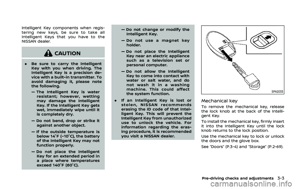
Mechanical key
To remove the mechanical key, release
the lock knob at the back of the Intelli-
gent Key.
To install the mechanical key, firmly insert
it into the Intelligent Key until the lock
knob returns to the lock position.
Use the mechanical key to lock or unlock
the doors and the glove box.
See “Doors” (P.3-4) and “Storage” (P.2-69).
Pre-driving checks and adjustments3-3
Page 196 of 604
3-8Pre-driving checks and adjustments
affect the system function.
. Do not drop the Intelligent Key.
. Do not strike the Intelligent Key
sharply against another object.
. Do not change or modify the
Intelligent Key.
. Wetting may damage the Intelli-
gent Key. If the Intelligent Key
gets wet, immediately wipe until
it is completely dry.
. If the outside temperature is be-
low 14°F (−10°C), the battery of the
Intelligent Key may not function
properly.
. Do not place the Intelligent Key
for an extended period in an area
where temperatures exceed
140°F (60°C).
. Do not attach the Intelligent Key
with a key holder that contains a
magnet.
. Do not place the Intelligent Key
near equipment that produces a
magnetic field, such as a TV,
audio equipment and personal
computers or wireless charger (if
so equipped).
If an Intelligent Key is lost or stolen,
NISSAN recommends erasing the ID code of that Intelligent Key from the vehicle.
This may prevent the unauthorized use of
the Intelligent Key to operate the vehicle.
For information regarding the erasing
procedure, it is recommended that you
contact a NISSAN dealer.
Page 326 of 604
5-14Starting and driving
moved to the P (Park) position.
When the ignition switch cannot be
pushed toward the LOCK position, pro-
ceed as follows:
1. Move the shift lever into the P (Park)position.
2. Push the ignition switch to the OFF position. The ignition switch position
indicator will not illuminate.
3. Open the door. The ignition switch will change to the LOCK position.
The shift lever can be moved from the P
(Park) position if the ignition switch is in
the ON position and the brake pedal is
depressed.
If the battery of the vehicle is dis-
charged, the push-button ignition
switch cannot be turned from the LOCK
position.
Some indicators and warnings for opera-
tion are displayed on the vehicle informa-
tion display between the speedometer
and tachometer. (See “Vehicle informa-
tion display” (P.2-20).)PUSH-BUTTON IGNITION SWITCH
POSITIONS
LOCK (Normal parking position)
The ignition switch can only be locked in
this position.
The ignition switch will be unlocked when
it is pushed to the ACC position while
carrying the Intelligent Key.
ACC (Accessories)
This position activates electrical acces-
sories such as the radio, when the engine
is not running.
ACC has a battery saver feature that will
turn the ignition switch to the OFF posi-
tion after a period of time under the
following conditions:
. all doors are closed.
. shift lever is in P (Park).
. turn signal/hazard indicator lights are
not flashing.
The battery saver feature will be can-
celled if any of the following occur:
. any door is opened.
. shift lever is moved out of P (Park).
. ignition switch changes position.
ON (Normal operating position)
This position turns on the ignition system
and electrical accessories.
ON has a battery saver feature that will
turn the ignition switch to the OFF posi-
tion, if the vehicle is not running, after
some time under the following condi-
tions:
. all doors are closed.
. shift lever is in P (Park).
. turn signal/hazard indicator lights are
not flashing.
The battery saver feature will be can-
celled if any of the following occur:
. any door is opened.
. shift lever is moved out of P (Park).
. ignition switch changes position.
OFF
The engine can be turned off in the
position.
The ignition lock is designed so that the
ignition switch cannot be switched to the
LOCK position until the shift lever is
moved to the P (Park) position.
Page 327 of 604
CAUTION
Do not leave the vehicle with the
push-button ignition switch in ACC or
ON positions when the engine is not
running for an extended period. This
can discharge the battery.
ACC (Accessories) delay timer
function
When the ignition switch is placed in the
OFF position, the ACC (Accessories) delay
timer function is activated. This function
keeps the power supply to the electrical
accessories for up to 10 minutes. When
the driver’s door is opened, this function is
canceled and the electrical power supply
is stopped. The ACC (Accessories) delay
time function can be enabled or disabled.
(See “Vehicle settings” (P.2-24).)
EMERGENCY ENGINE SHUT OFF
To shut off the engine in an emergency
situation while driving, perform the fol-
lowing procedure:
.Rapidly push the push-button ignition
switch 3 consecutive times in less
than 1.5 seconds, or
. Push and hold the push-button igni-
tion switch for more than 2 seconds.
JVS0404X
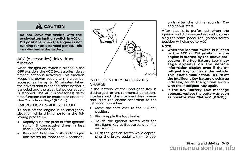
INTELLIGENT KEY BATTERY DIS-
CHARGE
If the battery of the Intelligent Key is
discharged, or environmental conditions
interfere with the Intelligent Key opera-
tion, start the engine according to the
following procedure:
1. Move the shift lever to the P (Park)
position.
2. Firmly apply the foot brake.
3. Touch the ignition switch with the Intelligent Key as illustrated. (A chime
will sound.)
4. Push the ignition switch while depres- sing the brake pedal within 10 sec- onds after the chime sounds. The
engine will start.
After step 3 is performed, when the
ignition switch is pushed without depres-
sing the brake pedal, the ignition switch
position will change to ACC.
NOTE:
. When the ignition switch is pushed
to the ACC or ON position or the
engine is started by the above pro-
cedures, the Key Battery Low mes-
sage appears on the vehicle
information display even if the In-
telligent Key is inside the vehicle.
This is not a malfunction. To turn off
the Intelligent Key battery discharge
indicator, touch the ignition switch
with the Intelligent Key again.
. If the Key Battery Low message
appears, replace the battery as soon
as possible. (See “Battery” (P.8-11).)
Starting and driving5-15
Page 329 of 604
fuel cut mode.
5. To stop the engine, shift the shift lever to the P (Park) position and push the
ignition switch to the OFF position.
In preparation for the next engine start,
the engine may have a slightly delayed
shutoff after placing the ignition switch in
the OFF position, depending on the driv-
ing conditions.
NOTE:
Care should be taken to avoid situations
that can lead to potential battery dis-
charge and potential no-start condi-
tions such as:
1. Installation or extended use of elec-
tronic accessories that consume
battery power when the engine is
not running (Phone chargers, GPS,
DVD players, etc.)
2. Vehicle is not driven regularly and/
or only driven short distances.
In these cases, the battery may need to
be charged to maintain battery health.
REMOTE ENGINE START (if so
equipped)
Vehicles started with the remote engine
start function require the ignition switch
to be placed in the ON position before the
shift lever can be moved from the P (Park)
position. To place the ignition switch in the ON position, perform the following
steps:
1. Make sure that the Intelligent Key is
on you.
2. Firmly depress the brake pedal.
3. Push the ignition switch once to the ON position.
For additional information about the
remote engine start function, see “Re-
mote engine start” (P.3-19).
ENGINE PROTECTION MODE
The engine has an engine protection
mode to reduce the chance of damage
if the coolant temperature becomes too
high (for example, when climbing steep
grades in high temperature with heavy
loads, such as when towing a trailer).
When the engine temperature reaches a
certain level:
. The engine coolant temperature
gauge will move toward the H posi-
tion.
. Engine power may be reduced.
. The air conditioning cooling function
may be automatically turned OFF for a
short time (the blower will continue to
operate).
Engine power and, under some condi-
tions, vehicle speed will decrease. Vehicle
speed can be controlled with the accel-
erator pedal, but the vehicle may not
accelerate at the desired speed. The
transmission will downshift or upshift as
it reaches prescribed shift points. You can
also shift manually.
As driving conditions change and engine
coolant temperature is reduced, vehicle
speed can be increased using the accel-
erator pedal, and air conditioning cooling
function will automatically be turned
back ON.
Starting and driving5-17
DRIVING THE VEHICLE