2022 NISSAN ARMADA light
[x] Cancel search: lightPage 150 of 604

2-56Instruments and controls
.Any liquid spilled on the heated
seat should be removed immedi-
ately with a dry cloth.
. When cleaning the seat, never use
gasoline, thinner, or any similar
materials.
. If any malfunctions are found or
the heated seat does not operate,
turn the switch off and have the
system checked. It is recom-
mended you visit a NISSAN dealer
for this service.
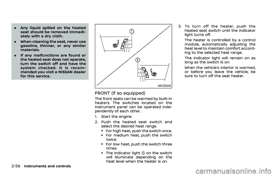
WAC0524X
FRONT (if so equipped)
The front seats can be warmed by built-in
heaters. The switches located on the
instrument panel can be operated inde-
pendently of each other.
1. Start the engine.
2. Push the heated seat switch and
select the desired heat range.
.For high heat, push the switch once..For medium heat, push the switch
twice.
.For low heat, push the switch threetimes.
.The indicator lighton the switch
will illuminate depending on the
heat level when the heater is on. 3. To turn off the heater, push the
heated seat switch until the indicator
light turns off.
The heater is controlled by a control
module, automatically adjusting the
heat level to maintain comfort accord-
ing to the selected heat range.
The indicator light will remain on as
long as the switch is on.
When the vehicle’s interior is warmed,
or before you leave the vehicle, be
sure to turn off the seat heater.
Page 151 of 604

SIC2770
REAR (if so equipped)
The 2nd row outboard seats are warmed
by built-in heaters. The switches located
on the back side of the center console
can be operated independently of each
other.
1. Start the engine.
2. Select heat range.
For high heat, push the HI (High)
side of the switch.
For low heat, push the LO (Low) side
of the switch.
The indicator light in the switch
will
illuminate when the heater is on. 3. To turn off the heater, return the
switch to the level position. Make sure
the indicator light turns off.
The heater is controlled by a thermo-
stat, automatically turning the heater
on and off. The indicator light will
remain on as long as the switch is on.
When the vehicle’s interior is warmed,
or before you leave the vehicle, be
sure to turn off the switch.
WAC0640X
The climate controlled seat cools down
the front seats by blowing cool air from
the surface of the seat. The switches
located on the instrument panel can be
operated independently of each other.
1. Start the engine.
2. Push the climate controlled seatswitch to cool the seat. The indicator
light
on the corresponding switch
will illuminate depending on the cool
level.
3. Adjust the desired amount of air by pushing the switch again. The climate
controlled seat blower remains on low
speed for approximately 60 seconds
after pushing the switch on.
Instruments and controls2-57
CLIMATE CONTROLLED SEATS (if
so equipped)
Page 152 of 604

2-58Instruments and controls
4. When the vehicle’s interior is warmedor cooled, or before you leave the
vehicle, be sure to turn off the climate
controlled seats. To turn off the cli-
mate controlled seats, push the
switch until the indicator light turns
off.
To check the air filters for the climate
controlled seat, it is recommended
you visit a NISSAN dealer.
WARNING
Do not use or allow occupants to use
the climate controlled seats if you or
the occupants cannot monitor seat
temperatures or have an inability to
feel pain in those body parts in
contact with the seat. Use of the
climate controlled seats by such
people could result in serious injury.
CAUTION
.The battery could run down if the
climate controlled seat is oper-
ated while the engine is not run-
ning. .
Do not use the climate controlled
seat for extended periods or
when no one is using the seat.
. Do not put anything on the seat
which insulates heat, such as a
blanket, cushion, seat cover, etc.
Otherwise, the seat may become
overheated.
. Do not place anything hard or
heavy on the seat or pierce it with
a pin or similar object. This may
result in damage to the climate
controlled seat.
. Any liquid spilled on the seat
should be removed immediately
with a dry cloth.
. The climate controlled seat has
an air filter. Do not operate cli-
mate controlled seat without an
air filter. This may result in da-
mage to the system.
. When cleaning the seat, never use
gasoline, thinner, or any similar
materials.
. If any malfunctions are found or
the climate controlled seat does
not operate, turn the switch off
and have the system checked. It
is recommended you visit a
NISSAN dealer for this service.
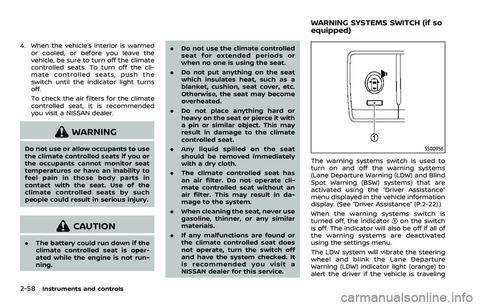
SSD0956
The warning systems switch is used to
turn on and off the warning systems
(Lane Departure Warning (LDW) and Blind
Spot Warning (BSW) systems) that are
activated using the “Driver Assistance”
menu displayed in the vehicle information
display. (See “Driver Assistance” (P.2-22).)
When the warning systems switch is
turned off, the indicator
on the switch
is off. The indicator will also be off if all of
the warning systems are deactivated
using the settings menu.
The LDW system will vibrate the steering
wheel and blink the Lane Departure
Warning (LDW) indicator light (orange) to
alert the driver if the vehicle is traveling
WARNING SYSTEMS SWITCH (if so
equipped)
Page 153 of 604

close to either the left or the right of a
traveling lane with detectable lane mar-
kers. (See “Lane Departure Warning (LDW)”
(P.5-26).)
The BSW system will turn on the side
indicator lights, on the outside mirrors, if
the radar sensors detect a vehicle in the
detection zone. If the turn signal is
activated in the direction of the detected
vehicle, a chime sounds twice and the
side indicator light will flash. (See “Blind
Spot Warning (BSW)” (P.5-38).)
SIC4454
For driving or starting the vehicle on
snowy roads or slippery areas, push on
the SNOW mode switch. The SNOW mode
indicator will illuminate. When the SNOW
mode is activated, engine output is con-
trolled to avoid wheel spin.
Push off the SNOW mode for normal
driving.
NOTE:
When the SNOW mode is activated, the
I-LI, I-BSI, and ICC systems will be turned
off automatically.
SIC4474
TOW MODE should be used when pulling
a heavy trailer or hauling a heavy load.
Driving the vehicle in TOW MODE with no
trailer/load or light trailer/light load will
not cause any damage. However, fuel
economy may be reduced, and the trans-
mission/engine driving characteristics
may feel unusual.
Push the TOW MODE switch to activate
TOW MODE. The indicator light on the
TOW MODE switch illuminates when TOW
MODE is selected. Push the TOW MODE
switch again to turn TOW MODE OFF.
TOW MODE is automatically canceled
when the ignition switch is placed in the
OFF position.
Instruments and controls2-59
SNOW MODE SWITCHTOW MODE SWITCH
Page 156 of 604

2-62Instruments and controls
(See “42. Rear Door Alert is activated” (P.2-
34).)
CAUTION
.Use power outlet with the engine
running to avoid discharging the
vehicle battery.
. Avoid using power outlet when
the air conditioner, headlights or
rear window defroster is on.
. Before inserting or disconnecting
a plug, be sure the electrical
accessory being used is turned
OFF.
. When not in use, be sure to close
the cap. Do not allow water or any
liquid to contact the outlet.
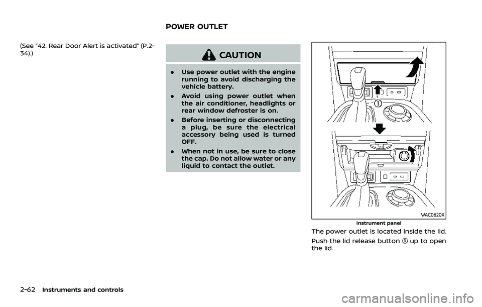
WAC0620XInstrument panel
The power outlet is located inside the lid.
Push the lid release button
up to open
the lid.
POWER OUTLET
Page 157 of 604

SIC4456
Back side of front console
SIC4391Luggage room
Type A (if so equipped)
The power outlet is used for powering
electrical accessories such as cellular
telephones.
CAUTION
.The outlet and plug may be hot
during or immediately after use.
. Do not use with accessories that
exceed a combined power draw
of 12 volts, 120W (10A) for all the
power outlets. Do not use double
adapters or more than one elec-
trical accessory.
. This power outlet is not designed
for use with a cigarette lighter
unit.
. Push the plug in as far as it will
go. If good contact is not made,
the plug may overheat or the
internal temperature fuse may
blow.
SIC2648
Main switch
Type B (if so equipped)
The power outlet (plug type) is located on
the back side of the front console. It can
operate when the ignition switch in the
ON position and the main switch (located
in the console box) is ON.
The specification of this power outlet is
for use of a 120 volt, 150W (1.25A) power
draw.
To turn on or off the power supply to the
outlet, push the ON
or OFFside of the
main switch. When the switch is turned to
the ON position, the indicator light
will
illuminate.
Instruments and controls2-63
Page 159 of 604

WAC0621X
1. Lid release button
2. Charging pad
3. Indicator
WIRELESS CHARGER (if so equipped)
The wireless charger is located inside the
lid. Push the lid release button up to open
the lid. Place the smartphone on the padof the wireless charger with screen face
up. Charging will start automatically. The
smartphone will be charged continuously
while the ignition switch is in the ON
position.
WARNING
.
Never put metallic materials be-
tween the wireless charger and a
smartphone.
. Those who use a pacemaker or
other medical equipment should
contact the electric medical
equipment manufacturer for the
possible influences before use.
. Never put cloth over the smart-
phone during charging process.
. Never charge a smartphone when
it is wet.
. Never put metallic materials or
small goods such as a cigarette
lighter, Intelligent Key or memory
drive.
CAUTION
.Do not put an RFID/NFC/credit
card between the wireless char-
ger and a smartphone. This could
cause data corruption in the card.
. Do not use the wireless charger
with dust accumulated or dirt on
the pad.
. Do not hit the surface of the
wireless charger.
. Do not spill liquid (water, drinks,
etc.) on the charging pad.
. Do not use grease, oil or alcohol
for cleaning charging pad.
Wireless charger Indicator
The indicatorwill illuminate in orange
when the charging process is started.
When the charging has completed, the
indicator illuminates in green.
If a malfunction occurs or the charging
process has stopped, the indicator will
blink in orange for 8 seconds then turn
off.
Instruments and controls2-65
Page 162 of 604

2-68Instruments and controls
collision and/or emergency.
. Park the vehicle in a safe location
and set the parking brake before
operating the Emergency Call
(SOS) button.
. Only use this service in case of an
emergency. There may be a pen-
alty for inappropriate use of the
service.
. Radio waves could adversely af-
fect electric medical equipment.
Individuals who use a pacemaker
should contact the device manu-
facturer regarding any possible
effects before using the system.
. The TCU (Telematics Control Unit)
antenna is installed inside the
upper central part of the instru-
ment panel. An occupant should
not get any closer to the antenna
than specified by the pacemaker
manufacturer. The radio waves
from the TCU antenna may ad-
versely affect the operation of the
pacemaker while using the Nis-
sanConnect® Services.
WAC0510X
Making an emergency call
The Emergency Call (SOS) button is lo-
cated near the map light.
1. Push the Emergency Call (SOS) button
to make an emergency call.
2. When the line is connected, speak to the Response Specialist.
If you want to cancel the emergency call,
push and hold the Emergency Call (SOS)
button for a few seconds.
NOTE:
. After the Emergency Call (SOS) but-
ton is pushed, it may take some time
until the system initiates connec-
tion, depending on the technical environment and whether the TCU
(Telematics Control Unit) is being
used by other services.
. An indicator light on the Emergency
Call (SOS) button shows the readi-
ness of the emergency support sys-
tem. If the indicator light is not
illuminated, pushing the Emergency
Call (SOS) button does not connect
your vehicle to the Response Spe-
cialist.
The indicator light blinks while con-
nected to the NissanConnect® Ser-
vices Response Center.
. Even when the indicator light is
illuminated, connection to the Nis-
sanConnect® Services Response
Center may not be possible. If this
occurs in an emergency situation,
contact the authorities by other
means.
. To avoid disconnecting the line,
keep the engine running during an
emergency call, if it is safe to do so.