2022 NISSAN ARMADA brake light
[x] Cancel search: brake lightPage 441 of 604
.If it is difficult to free the vehicle,
repeat forward and backward move-
ment to increase the movement.
. If the vehicle is stuck deep in mud, tire
chains may be effective.
CAUTION
.Do not spin the tires excessively.
Tires will sink deep into the mud,
making it difficult to free the
vehicle.
. Avoid shifting gears with the en-
gine running at high speeds as
this may cause malfunction.
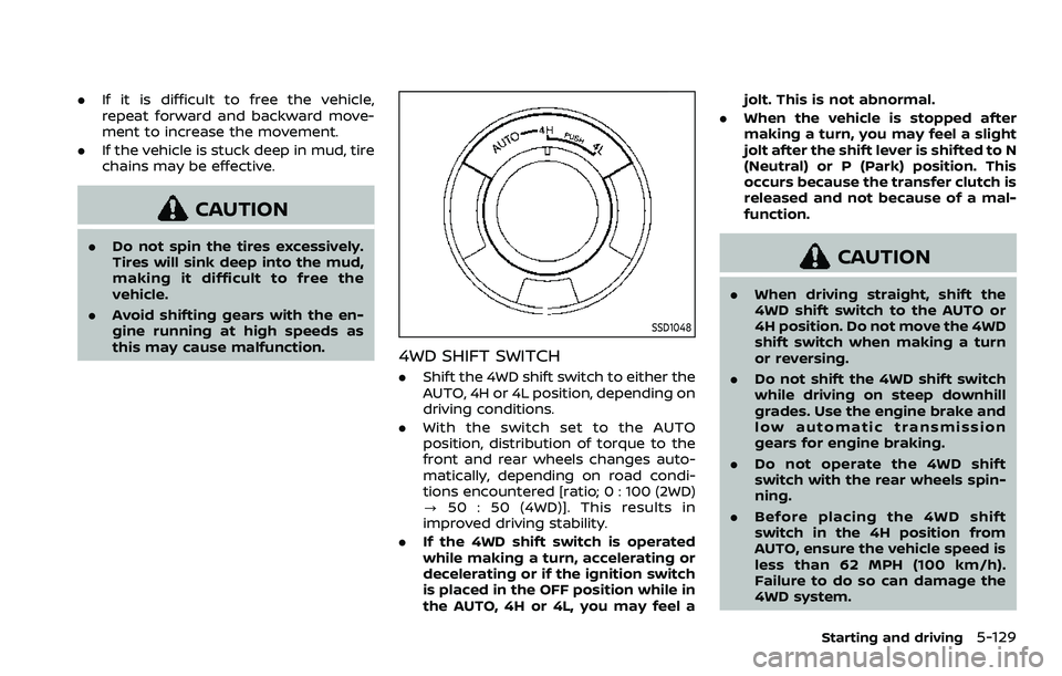
SSD1048
4WD SHIFT SWITCH
.Shift the 4WD shift switch to either the
AUTO, 4H or 4L position, depending on
driving conditions.
. With the switch set to the AUTO
position, distribution of torque to the
front and rear wheels changes auto-
matically, depending on road condi-
tions encountered [ratio; 0 : 100 (2WD)
? 50 : 50 (4WD)]. This results in
improved driving stability.
. If the 4WD shift switch is operated
while making a turn, accelerating or
decelerating or if the ignition switch
is placed in the OFF position while in
the AUTO, 4H or 4L, you may feel a jolt. This is not abnormal.
. When the vehicle is stopped after
making a turn, you may feel a slight
jolt after the shift lever is shifted to N
(Neutral) or P (Park) position. This
occurs because the transfer clutch is
released and not because of a mal-
function.
CAUTION
.When driving straight, shift the
4WD shift switch to the AUTO or
4H position. Do not move the 4WD
shift switch when making a turn
or reversing.
. Do not shift the 4WD shift switch
while driving on steep downhill
grades. Use the engine brake and
low automatic transmission
gears for engine braking.
. Do not operate the 4WD shift
switch with the rear wheels spin-
ning.
. Before placing the 4WD shift
switch in the 4H position from
AUTO, ensure the vehicle speed is
less than 62 MPH (100 km/h).
Failure to do so can damage the
4WD system.
Starting and driving5-129
Page 444 of 604
5-132Starting and driving
WARNING
.Never rely solely on the hill start
assist system to prevent the ve-
hicle from moving backward on a
hill. Always drive carefully and
attentively. Depress the brake
pedal when the vehicle is stopped
on a steep hill. Be especially care-
ful when stopped on a hill on
frozen or muddy roads. Failure
to prevent the vehicle from rolling
backwards may result in a loss of
control of the vehicle and possi-
ble serious injury or death.
. The hill start assist system is not
designed to hold the vehicle at a
standstill on a hill. Depress the
brake pedal when the vehicle is
stopped on a steep hill. Failure to
do so may cause the vehicle to
roll backwards and may result in
a collision or serious personal
injury.
. The hill start assist system may
not prevent the vehicle from roll-
ing backwards on a hill under all
load or road conditions. Always
be prepared to depress the brake
pedal to prevent the vehicle from
rolling backwards. Failure to do so may result in a collision or
serious personal injury.
The hill start assist system automatically
keeps the brakes applied to help prevent
the vehicle from rolling backwards in the
time it takes the driver to release the
brake pedal and apply the accelerator
when the vehicle is stopped on a hill.
The hill start assist system will operate
automatically under the following condi-
tions:
. The transmission is shifted to a for-
ward or reverse gear.
. The vehicle is stopped completely on a
hill by applying the brake.
The maximum holding time is 2 seconds.
After 2 seconds the vehicle will begin to
roll back and the hill start assist system
will stop operating completely.
The hill start assist system will not
operate when the transmission is shifted
to the N (Neutral) or P (Park) position or
on a flat and level road.
When the Vehicle Dynamic Control (VDC)
warning light illuminates in the meter, the
hill start assist system will not operate.
(See “Warning lights, indicator lights and
audible reminders” (P.2-11).)
HILL START ASSIST SYSTEM
Page 454 of 604
5-142Starting and driving
BRAKING PRECAUTIONS
The brake system has two separate
hydraulic circuits. If one circuit malfunc-
tions, you will still have braking ability at
two wheels.
You may feel a small click and hear a
sound when the brake pedal is fully
depressed slowly. This is not a malfunc-
tion and indicates that the brake assist
mechanism is operating properly.
Hydraulically-assisted brakes
The hydraulically-assisted brake system is
designed to use a hydraulic pump driven
electrically, to assist braking. If the engine
stops, you can stop the vehicle by de-
pressing the foot brake pedal. However,
greater foot pressure on the foot brake
pedal will be required to stop the vehicle.
The stopping distance will be longer.
Wet brakes
When the vehicle is washed or driven
through water, the brakes may get wet.
As a result, your braking distance will be
longer and the vehicle may pull to one
side during braking.
To dry brakes, drive the vehicle at a safe
speed while lightly tapping the brake
pedal to heat-up the brakes. Do this until
the brakes return to normal. Avoid driving
the vehicle at high speeds until the brakesfunction correctly.
PARKING BRAKE BREAK-IN
Break in the parking brake shoes when-
ever the stopping effect of the parking
brake is weakened or whenever the
parking brake shoes and/or drums/ro-
tors are replaced, in order to assure the
best braking performance.
This procedure is described in the vehicle
service manual. It is recommended you
visit a NISSAN dealer for this service.
Using the brakes
Avoid resting your foot on the brake
pedal while driving. This will cause over-
heating of the brakes, wearing out the
brake and pads faster and reduce gas
mileage.
To help save the brakes and to prevent
the brakes from overheating, reduce
speed and downshift to a lower gear
before going down a slope or long grade.
Overheated brakes may reduce braking
performance and could result in loss of
vehicle control.
WARNING
.
While driving on a slippery sur-
face, be careful when braking,
accelerating or downshifting. Abrupt braking or accelerating
could cause the wheels to skid
and result in an accident.
. If the engine is not running or is
turned off while driving, the
power assist for the brakes will
not work. Braking will be harder.
BRAKE SYSTEM
Page 455 of 604

BRAKE ASSIST
When the force applied to the brake pedal
exceeds a certain level, the Brake Assist is
activated generating greater braking
force than a conventional brake booster
even with light pedal force.
WARNING
The Brake Assist is only an aid to
assist braking operation and is not a
collision warning or avoidance de-
vice. It is the driver’s responsibility to
stay alert, drive safely and be in
control of the vehicle at all times.
ANTI-LOCK BRAKING SYSTEM (ABS)
WARNING
.The Anti-lock Braking System
(ABS) is a sophisticated device,
but it cannot prevent accidents
resulting from careless or dan-
gerous driving techniques. It can
help maintain vehicle control dur-
ing braking on slippery surfaces.
Remember that stopping dis-
tances on slippery surfaces will
be longer than on normal sur- faces even with ABS. Stopping
distances may also be longer on
rough, gravel or snow covered
roads, or if you are using tire
chains. Always maintain a safe
distance from the vehicle in front
of you. Ultimately, the driver is
responsible for safety.
. Tire type and condition may also
affect braking effectiveness.
— When replacing tires, install
the specified size of tires on
all four wheels.
— When installing a spare tire, make sure that it is the proper
size and type as specified on
the Tire and Loading Informa-
tion label. See “Tire and load-
ing information label” (P.10-
13).
— For detailed information, see “Wheels and tires” (P.8-28).
The Anti-lock Braking System (ABS) con-
trols the brakes so the wheels do not lock
during hard braking or when braking on
slippery surfaces. The system detects the
rotation speed at each wheel and varies
the brake fluid pressure to prevent each
wheel from locking and sliding. By pre-
venting each wheel from locking, the system helps the driver maintain steering
control and helps to minimize swerving
and spinning on slippery surfaces.
Using the system
Depress the brake pedal and hold it down.
Depress the brake pedal with firm steady
pressure, but do not pump the brakes.
The ABS will operate to prevent the
wheels from locking up. Steer the vehicle
to avoid obstacles.
WARNING
Do not pump the brake pedal. Doing
so may result in increased stopping
distances.
Self-test feature
The ABS includes electronic sensors, elec-
tric pumps, hydraulic solenoids and a
computer. The computer has a built-in
diagnostic feature that tests the system
each time you start the engine and move
the vehicle at a low speed in forward or
reverse. When the self-test occurs, you
may hear a “clunk” noise and/or feel a
pulsation in the brake pedal. This is
normal and does not indicate a malfunc-
tion. If the computer senses a malfunc-
tion, it switches the ABS off and
Starting and driving5-143
BRAKE ASSIST
Page 456 of 604
5-144Starting and driving
illuminates the ABS warning light on the
instrument panel. The brake system then
operates normally, but without anti-lock
assistance.
If the ABS warning light illuminates during
the self-test or while driving, have the
vehicle checked. It is recommended you
visit a NISSAN dealer for this service.
Normal operation
The ABS operates at speeds above 3 to 6
MPH (5 to 10 km/h). The speed varies
according to road conditions.
When the ABS senses that one or more
wheels are close to locking up, the
actuator rapidly applies and releases
hydraulic pressure. This action is similar
to pumping the brakes very quickly. You
may feel a pulsation in the brake pedal
and hear a noise from under the hood or
feel a vibration from the actuator when it
is operating. This is normal and indicates
that the ABS is operating properly. How-
ever, the pulsation may indicate that road
conditions are hazardous and extra care
is required while driving.The Vehicle Dynamic Control (VDC) sys-
tem uses various sensors to monitor
driver inputs and vehicle motion. Under
certain driving conditions, the VDC sys-
tem helps to perform the following func-
tions.
.
Controls brake pressure to reduce
wheel slip on one slipping drive wheel
so power is transferred to a non
slipping drive wheel on the same axle.
. Controls brake pressure and engine
output to reduce drive wheel slip
based on vehicle speed (traction con-
trol function).
. Controls brake pressure at individual
wheels and engine output to help the
driver maintain control of the vehicle
in the following conditions:
— understeer (vehicle tends to not
follow the steered path despite
increased steering input)
— oversteer (vehicle tends to spin due to certain road or driving condi-
tions).
The VDC system can help the driver to
maintain control of the vehicle, but it
cannot prevent loss of vehicle control in
all driving situations.
When the VDC system operates, the VDC
warning light
in the instrument panel
flashes so note the following: .
The road may be slippery or the
system may determine some action
is required to help keep the vehicle on
the steered path.
. You may feel a pulsation in the brake
pedal and hear a noise or vibration
from under the hood. This is normal
and indicates that the VDC system is
working properly.
. Adjust your speed and driving to the
road conditions.
If a malfunction occurs in the system, the
VDC warning light
illuminates in the
instrument panel. The VDC system auto-
matically turns off.
The VDC OFF switch is used to turn off the
VDC system. The VDC off indicator
illuminates to indicate the VDC system is
off. When the VDC switch is used to turn
off the system, the VDC system still
operates to prevent one drive wheel from
slipping by transferring power to a non
slipping drive wheel. The VDC warning
light
flashes if this occurs. All other
VDC functions are off, and the VDC
warning light
will not flash. The VDC
system is automatically reset to on when
the ignition switch is placed in the OFF
position then back to the ON position.
When the 4L position is selected with the
4WD shift switch, the VDC system is
disabled and the VDC off indicator light
VEHICLE DYNAMIC CONTROL (VDC) SYSTEM
Page 457 of 604

illuminates (for 4WD models).
See “Vehicle Dynamic Control (VDC) warn-
ing light” (P.2-19) and “Vehicle Dynamic
Control (VDC) off indicator light” (P.2-19).
The computer has a built-in diagnostic
feature that tests the system each time
you start the engine and move the vehicle
forward or in reverse at a slow speed.
When the self-test occurs, you may hear a
“clunk” noise and/or feel a pulsation in the
brake pedal. This is normal and is not an
indication of a malfunction.
WARNING
.The VDC system is designed to
help improve driving stability but
does not prevent accidents due
to abrupt steering operation at
high speeds or by careless or
dangerous driving techniques.
Reduce vehicle speed and be
especially careful when driving
and cornering on slippery sur-
faces and always drive carefully.
. Do not modify the vehicle’s sus-
pension. If suspension parts such
as shock absorbers, struts,
springs, stabilizer bars, bushings
and wheels are not NISSAN re-
commended for your vehicle or are extremely deteriorated, the
VDC system may not operate
properly. This could adversely
affect vehicle handling perfor-
mance, and the VDC warning light
may illuminate.
. If brake related parts such as
brake pads, rotors and calipers
are not NISSAN recommended or
are extremely deteriorated, the
VDC system may not operate
properly and the VDC warning
light
may illuminate.
. If engine control related parts are
not NISSAN recommended or are
extremely deteriorated, the VDC
warning light
may illuminate.
. When driving on extremely in-
clined surfaces such as higher
banked corners, the VDC system
may not operate properly and the
VDC warning light
may illumi-
nate. Do not drive on these types
of roads.
. When driving on an unstable sur-
face such as a turntable, ferry,
elevator or ramp, the VDC warn-
ing light
may illuminate. This
is not a malfunction. Restart the
engine after driving onto a stable
surface. .
If wheels or tires other than the
NISSAN recommended ones are
used, the VDC system may not
operate properly and the VDC
warning light
may illuminate.
. The VDC system is not a substi-
tute for winter tires or tire chains
on a snow covered road.
Starting and driving5-145
Page 473 of 604
WAG0119X
WARNING
Always follow the instructions below.
Failure to do so could result in
damage to the charging system and
cause personal injury.
1. Remove the engine compartment cover, if necessary. See “Engine com-
partment check locations” (P.8-3).
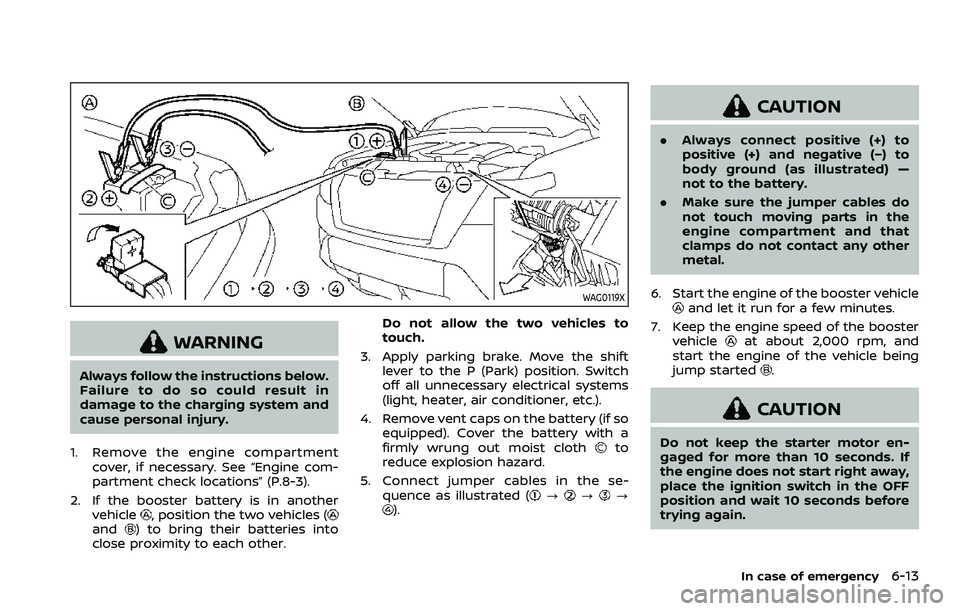
2. If the booster battery is in another vehicle
, position the two vehicles (and) to bring their batteries into
close proximity to each other. Do not allow the two vehicles to
touch.
3. Apply parking brake. Move the shift lever to the P (Park) position. Switch
off all unnecessary electrical systems
(light, heater, air conditioner, etc.).
4. Remove vent caps on the battery (if so equipped). Cover the battery with a
firmly wrung out moist cloth
to
reduce explosion hazard.
5. Connect jumper cables in the se- quence as illustrated (
???).
CAUTION
.Always connect positive (+) to
positive (+) and negative (−) to
body ground (as illustrated) —
not to the battery.
. Make sure the jumper cables do
not touch moving parts in the
engine compartment and that
clamps do not contact any other
metal.
6. Start the engine of the booster vehicle
and let it run for a few minutes.
7. Keep the engine speed of the booster vehicle
at about 2,000 rpm, and
start the engine of the vehicle being
jump started
.
CAUTION
Do not keep the starter motor en-
gaged for more than 10 seconds. If
the engine does not start right away,
place the ignition switch in the OFF
position and wait 10 seconds before
trying again.
In case of emergency6-13
Page 480 of 604
6-20In case of emergency
This section describes the procedure for
manually shifting the vehicle into the 4WD
mode (4L position) in case of an emer-
gency.
WHEN 4WD WARNING LIGHT ILLU-
MINATES
If the 4WD warning light illuminates while
driving, there may be a malfunction in the
4WD system. Stop the vehicle and have
the vehicle checked as soon as possible. It
is recommended you contact a NISSAN
dealer for this service. (See “NISSAN all-
mode 4WD®” (P.5-124).)
When the vehicle is stuck on an uneven
road (desert, mud, etc.) and the 4WD
warning light is illuminated, be sure to
place the 4WD shift switch in the 4L
position. If only the rear wheels are
spinning, this means that the transfer
has not switched to the 4L position
electrically.
If this situation occurs, contact a dealer or
road assistance service for help. If an
immediate service is not available, per-
form the following procedure to switch to
the 4L position manually and free the
vehicle.
CAUTION
Only perform this procedure in an
emergency.
If the vehicle is driven for a long
period of time over a long distance
with a component detached, foreign
material such as water, sand, etc.
may enter from the opening and this
may cause a malfunction in the
drivetrain system. After freeing a
vehicle that has become stuck, it is
recommended you contact a NISSAN
dealer for inspection and repair.
WARNING
.Ensure your safety before per-
forming the operations. The ve-
hicle may move unexpectedly.
. Place the ignition switch in the
OFF position, apply the parking
brake and let the vehicle cool
down.
. Do not perform the following
procedure immediately after
driving the vehicle. Parts such as
exhaust components, the trans- mission, etc. are very hot and
may cause a burn injury.
. Make sure that the parts that will
be operated as well as related
parts cool down before perform-
ing the operation.
. Burrs or projecting portions of
metal components may cause
unexpected injury to your fingers
or arms. Pay special attention in
regard to your safety while re-
moving and installing these
parts. Wear work gloves and pro-
tective arm covers.
CAUTION
While removing and installing the
parts, prevent the removed parts
from getting dirty with water, dirt or
sand. Protect the parts using a cover
such as a clean cloth, etc.
FOUR-WHEEL DRIVE (4WD)
MANUAL SHIFTING (4WD models)