2022 NISSAN ARMADA fog light
[x] Cancel search: fog lightPage 144 of 604

2-50Instruments and controls
High beam assist
The high beam assist system will operate
when the vehicle is driven at approxi-
mately 25 MPH (40 km/h) and above.
If an oncoming vehicle or leading vehicle
appears in front of your vehicle when the
headlight high beam is on, the headlight
will be switched to the low beam auto-
matically.
Precautions on high beam assist:
WARNING
.The high beam assist system is a
convenience but it is not a sub-
stitute for safe driving operation.
The driver should remain alert at
all times, ensure safe driving
practices and switch the high
beam and low beam manually
when necessary.
. The high beam or low beam may
not switch automatically under
the following conditions. Switch
the high beam and low beam
manually.
— During bad weather (rain, fog,
snow, wind, etc.). — When a light source similar to
a headlight or tail light is in
the vicinity of the vehicle.
— When the headlights of the oncoming vehicle or the lead-
ing vehicle are turned off,
when the color of the light is
affected due to foreign mate-
rials on the lights, or when the
light beam is out of position.
— When there is a sudden, con- tinuous change in brightness.
— When driving on a road that passes over rolling hills, or a
road that has level differ-
ences.
— When driving on a road with many curves.
— When a sign or mirror-like surface is reflecting intense
light towards the front of the
vehicle.
— When the container, etc. being towed by a leading vehicle is
reflecting intense light.
— When a headlight on your vehicle is damaged or dirty.
— When the vehicle is leaning at an angle due to a punctured tire, being towed, etc.
. The timing of switching the low
beam and high beam may
change under the following situa-
tions.
— The brightness of the head-
lights of the oncoming vehicle
or leading vehicle.
— The movement and direction of the oncoming vehicle and
the leading vehicle.
— When only one light on the oncoming vehicle or the lead-
ing vehicle is illuminated.
— When the oncoming vehicle or the leading vehicle is a two-
wheeled vehicle.
— Road conditions (incline, curve, the road surface, etc.).
— The number of passengers and the amount of luggage.
Page 148 of 604

2-54Instruments and controls
lever does not latch, and release the
lever. The turn signal will automati-
cally flash three times.
Choose the appropriate method to signal
a lane change based on road and traffic
conditions.
SIC3672
Example
FOG LIGHT SWITCH (if so equipped)
To turn the fog lights on, turn the head-
light switch to theposition, then turn
the switch to theposition. To turn
them off, turn the switch to the OFF
position.
The headlights must be on with the low
beams selected for the fog lights to
operate. The fog lights automatically turn
off when the high beam headlights are
selected.
SIC4401
The heated steering wheel system is
designed to operate only when the sur-
face temperature of the steering wheel is
below 68°F (20°C).
Push the heated steering wheel switch to
warm the steering wheel after the engine
starts. The indicator light
on the switch
will illuminate.
If the surface temperature of the steering
wheel is below 68°F (20°C), the system will
heat the steering wheel and cycle off and
on to maintain a temperature above 68°F
(20°C). The indicator light will remain on
as long as the system is on.
Push the switch again to turn the heated
steering wheel system off manually. The
HEATED STEERING WHEEL (if so equipped)
Page 225 of 604

JVP0559X
Flicker image (example)
.When LED headlights are viewed on
the Intelligent Rear View Mirror dis-
play, the images may flicker. This is
normal.
. Due to diffused reflection from ex-
ternal environment, images on the
screen may flicker. This is not a
malfunction.
. A quick movement of a thing may
not be able to display on the camera
view screen. This is not a malfunc-
tion.
. Turn on the headlights at twilight or
in a tunnel, etc. .
The Intelligent Rear View Mirror
mode (camera view mode) display
is different from the conventional
rearview mirror. Objects in the dis-
play may differ from actual distance.
Do not solely rely on the Intelligent
Rear View Mirror. Always rely on
your own operation to avoid acci-
dents.
. If the brightness of the camera view
display is adjusted to excessive
bright level, it may cause an eye-
strain in the driving. Adjust the
brightness properly.
. Use the rear window wiper when it
rains. If the camera view image is
still unclear when the rear window
wiper is in operation, check the
deterioration of the rear window
wiper blade.
. When using the rear window wiper,
images on the screen may flicker.
This is not a malfunction.
. Defog the rear window with defros-
ter when rear window is fogged. Use
the conventional rearview mirror
mode until the rear window is fully
defogged.
. The display of the Intelligent Rear
View Mirror may become hot. This is
not a malfunction. .
The color of an object in the distance
or in the dark may be difficult to be
recognized. This is not a malfunc-
tion.
System maintenance (Intelligent Rear
View Mirror):
. Always keep the mirror and camera
area of the rear window clean.
. Clean the mirror and the camera lens
with a dry soft cloth.
. When clean the camera area of the
rear window, using a soft cloth dam-
pend with water and a few neutral
detergent. And after, the dry it up with
dry soft cloth.
. If the image on the Intelligent Rear
View Mirror display screen is still un-
clear even after cleaning the camera
area of the rear window, an oil film
may be adhering to the rear window
glass. Clean the rear window glass
with an oil film remover.
. Never use alcohol, benzine, thinner, or
any similar material to clean the
mirror or camera lens. It will cause a
discoloration, deterioration or a sys-
tem malfunction.
. Do not attach a sticker (including
transparent material) on the camera
area of the rear window.
Pre-driving checks and adjustments3-37
Page 269 of 604
and fan speed are also controlled
automatically.
NOTE:
. Do not set the temperature lower
than the outside air temperature or
the system may not work properly.
. Not recommended if windows fog
up.
Dehumidified defrosting or defogging:
1. Push the
button. (The indicator
light on the button will illuminate.)
2. Turn the temperature control dial on the corresponding side to set the
desired temperature.
.To quickly remove ice from theoutside of the windows, use the
button to set the fan speed to
maximum.
.As soon as possible after the wind- shield is cleared, push the AUTO
button to return to the automatic
mode.
Manual operation
Fan speed control:
Push the
buttons to manually control
the fan speed.
Air intake control:
. Push the
button to recirculate
interior air inside the vehicle. (The
indicator light on the button will
illuminate.)
. Push the
button to draw outside
air into the passenger compartment.
(The indicator light on the button will
illuminate.)
. To control the air intake automatically,
push and hold either the
button
or thebutton. The indicator light
will blink, and then the air intake will
switch to automatic control. When the
automatic control is set, the system
automatically alternates between the
outside air circulation and the air
recirculation modes. (The indicator
light of the active mode will illumi-
nate.) Air flow control:
Pushing the
button manually con-
trols air flow and selects the air outlet:
— Air flows mainly from center and side
ventilators.
— Air flows mainly from center and sideventilators and foot outlets.
— Air flows mainly from the foot outletand partly from the defroster.
— Air flows mainly from the defrosterand foot outlets.
Synchronize temperature settings:
Push the SYNC button to turn on the
SYNC mode. (The indicator light on the
button will illuminate.)
When the SYNC mode is active, the
driver’s side temperature control dial will
control the driver’s side, front passenger’s
side and rear temperatures.
When the passenger’s side temperature
setting or the rear temperature setting is
changed, it will cancel the SYNC mode of
the operated individual zone. (The indica-
tor light on the SYNC button will turn off.)
Changing both the passenger’s side tem-
perature setting and the rear tempera-
ture setting will completely turn off the
SYNC mode.
Monitor, heater, air conditioner, audio, phone and voice recognition systems4-39
Page 273 of 604
OPERATING TIPS
When the engine coolant temperature
and outside air temperature are low, the
air flow from the foot outlets may not
operate. However, this is not a malfunc-
tion. After the coolant temperature
warms up, the air flow from the foot
outlets will operate normally.
The sensors
andlocated on the
instrument panel help maintain a con-
stant temperature. Do not put anything
on or around the sensors.
LINKING INTELLIGENT KEY (if so
equipped)
The air conditioner system settings can
be memorized for each Intelligent Key.
For more details, see “Setting memory
function” (P.3-42).
IN-CABIN MICROFILTER
The air conditioner system is equipped
with an in-cabin microfilter which collects
dirt, pollen, dust, etc.
To make sure the air conditioner heats,
defogs, and ventilates efficiently, replace
the filter in accordance with the specified
maintenance intervals listed in the “9.
Maintenance and schedules” section. It is
recommended to see a NISSAN dealer to
replace the filter.
The filter should be replaced if the air flow decreases significantly or if win-
dows fog up easily when operating the
heater or air conditioner.
SERVICING AIR CONDITIONER
The air conditioner system in your NISSAN
is charged with a refrigerant designed
with the environment in mind.
This re-
frigerant will not harm the earth’s
ozone layer. However, special charging
equipment and lubricant are required
when servicing your NISSAN air condi-
tioner. Using improper refrigerants or
lubricants will cause severe damage to
your air conditioner system. (See “Capa-
cities and recommended fluids/lubri-
cants” (P.10-2) for air conditioner system
refrigerant and lubricant recommenda-
tions.)
Your NISSAN dealer will be able to service
your environmentally friendly air condi-
tioner system.
WARNING
The system contains refrigerant un-
der high pressure. To avoid personal
injury, any air conditioner service
should be done only by an experi-
enced technician with the proper
equipment.
WINDOW ANTENNA
The antenna pattern is printed inside the
rear side glass.
CAUTION
. Do not place metalized film near
the 3rd row seat window or at-
tach any metal parts to it. This
may cause poor reception or
noise.
. When cleaning the inside of the
rear side window, be careful not
to scratch or damage the rear
side window antenna. Lightly
wipe along the antenna with a
dampened soft cloth.
Monitor, heater, air conditioner, audio, phone and voice recognition systems4-43
ANTENNA
Page 341 of 604
button. Use the OK to select “Driver
Assistance”. Then push the OK.
2. Select “Lane” and push the OK.
3. Select “Warning (LDW)” and push the OK.
The warning systems switch
is used to
turn on and off the LDW system when it is
activated on the vehicle information dis-
play. When the warning systems switch
is turned off, the warning systems ON
indicator lighton the switch is off.
The warning systems switch
will turn
on and off the LDW and BSW systems at
the same time.
NOTE:
If you disable the LDW system, the
system will remain disabled the next
time you start the vehicle’s engine.
LDW SYSTEM LIMITATIONS
WARNING
Listed below are the system limita-
tions for the LDW system. Failure to
follow the warnings and instructions
for proper use of the LDW system
could result in serious injury or
death. .
The system will not operate at
speeds below approximately 37
MPH (60 km/h) or if it cannot
detect lane markers.
. Do not use the LDW system under
the following conditions as it may
not function properly:
— During bad weather (rain, fog,
snow, etc.).
— When driving on slippery roads, such as on ice or snow.
— When driving on winding or uneven roads.
— When there is a lane closure due to road repairs.
— When driving in a makeshift or temporary lane.
— When driving on roads where the lane width is too narrow.
— When driving without normal tire conditions (for example,
tire wear, low tire pressure,
installation of spare tire, tire
chains, non-standard wheels).
— When the vehicle is equipped with non-original brake parts
or suspension parts. — When towing a trailer or other
vehicle.
. The system may not function
properly under the following con-
ditions:
— On roads where there are
multiple parallel lane markers;
lane markers that are faded or
not painted clearly; yellow
painted lane markers; non-
standard lane markers; or
lane markers covered with
water, dirt, snow, etc.
— On roads where discontinued lane markers are still detect-
able.
— On roads where there are sharp curves.
— On roads where there are sharply contrasting objects,
such as shadows, snow,
water, wheel ruts, seams or
lines remaining after road re-
pairs. (The LDW system could
detect these items as lane
markers.)
— On roads where the traveling lane merges or separates.
Starting and driving5-29
Page 347 of 604
activating your turn signal or, for
example, if a construction zone
directs traffic to cross an existing
lane marker. If this occurs you
may need to apply corrective
steering to complete your lane
change.
. Because the I-LI may not activate
under the road, weather, and lane
marker conditions described in
this section, it may not activate
every time your vehicle begins to
leave its lane and you will need to
apply corrective steering.
. The I-LI system will not operate at
speeds below approximately 37
MPH (60 km/h) or if it cannot
detect lane markers.
. When the I-LI system is operating,
avoid excessive or sudden steer-
ing maneuvers. Otherwise, you
could lose control of the vehicle.
. Do not use the I-LI system under
the following conditions as it may
not function properly:
— During bad weather (rain, fog,
snow, etc.).
— When driving on slippery roads, such as on ice or snow. — When driving on winding or
uneven roads.
— When there is a lane closure due to road repairs.
— When driving in a makeshift or temporary lane.
— When driving on roads where the lane width is too narrow.
— When driving without normal tire conditions (for example,
tire wear, low tire pressure,
installation of spare tire, tire
chains, non-standard wheels).
— When the vehicle is equipped with non-original brake parts
or suspension parts.
— When towing a trailer or other vehicle.
— On roads where there are multiple parallel lane markers;
lane markers that are faded or
not painted clearly; yellow
painted lane markers; non-
standard lane markers; or
lane markers covered with
water, dirt, snow, etc.
— On roads where discontinued lane markers are still detect-
able. — On roads where there are
sharp curves.
— On roads where there are sharply contrasting objects,
such as shadows, snow,
water, wheel ruts, seams or
lines remaining after road re-
pairs. (The I-LI system could
detect these items as lane
markers.)
— On roads where the traveling lane merges or separates.
— When the vehicle’s traveling direction does not align with
the lane marker.
— When traveling close to the vehicle in front of you, which
obstructs the lane camera
unit detection range.
— When rain, snow or dirt ad- heres to the windshield in
front of the lane camera unit.
— When the headlights are not bright due to dirt on the lens
or if the aiming is not adjusted
properly.
— When strong light enters the lane camera unit. (For exam-
ple, the light directly shines on
Starting and driving5-35
Page 356 of 604
5-44Starting and driving
WAF0555X
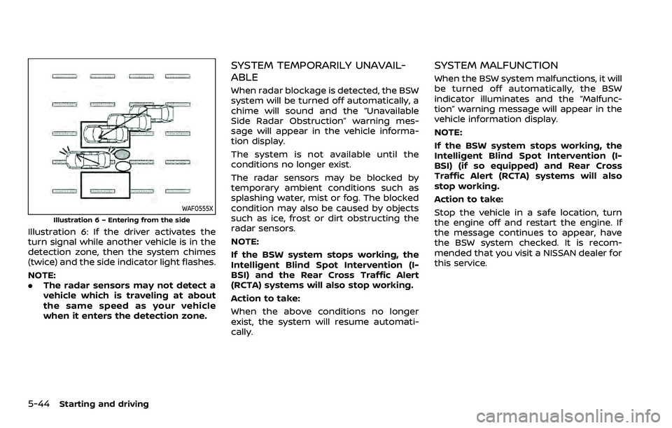
Illustration 6 – Entering from the side
Illustration 6: If the driver activates the
turn signal while another vehicle is in the
detection zone, then the system chimes
(twice) and the side indicator light flashes.
NOTE:
.The radar sensors may not detect a
vehicle which is traveling at about
the same speed as your vehicle
when it enters the detection zone.
SYSTEM TEMPORARILY UNAVAIL-
ABLE
When radar blockage is detected, the BSW
system will be turned off automatically, a
chime will sound and the “Unavailable
Side Radar Obstruction” warning mes-
sage will appear in the vehicle informa-
tion display.
The system is not available until the
conditions no longer exist.
The radar sensors may be blocked by
temporary ambient conditions such as
splashing water, mist or fog. The blocked
condition may also be caused by objects
such as ice, frost or dirt obstructing the
radar sensors.
NOTE:
If the BSW system stops working, the
Intelligent Blind Spot Intervention (I-
BSI) and the Rear Cross Traffic Alert
(RCTA) systems will also stop working.
Action to take:
When the above conditions no longer
exist, the system will resume automati-
cally.
SYSTEM MALFUNCTION
When the BSW system malfunctions, it will
be turned off automatically, the BSW
indicator illuminates and the “Malfunc-
tion” warning message will appear in the
vehicle information display.
NOTE:
If the BSW system stops working, the
Intelligent Blind Spot Intervention (I-
BSI) (if so equipped) and Rear Cross
Traffic Alert (RCTA) systems will also
stop working.
Action to take:
Stop the vehicle in a safe location, turn
the engine off and restart the engine. If
the message continues to appear, have
the BSW system checked. It is recom-
mended that you visit a NISSAN dealer for
this service.