2022 NISSAN ARMADA brake light
[x] Cancel search: brake lightPage 114 of 604

2-20Instruments and controls
AUDIBLE REMINDERS
Door lock warning chime
When the chime sounds, be sure to check
both the vehicle and the Intelligent Key.
(See “Troubleshooting guide” (P.3-13).)
Light reminder chime
A chime will sound when the driver side
door is opened with the headlight switch
in the
orposition and the ignition
switch in the ACC, OFF or LOCK position.
Turn the headlight switch to the OFF (if so
equipped) or the AUTO position when you
leave the vehicle.
Parking brake reminder chime
The chime will sound if the vehicle is
driven at more than 4 MPH (7 km/h) with
the parking brake applied. Stop the vehi-
cle and release the parking brake.
Brake pad wear warning
The disc brake pads have audible wear
warnings. When a brake pad requires
replacement, it will make a high pitched
scraping sound when the vehicle is in
motion. This scraping sound will first
occur only when the brake pedal is
depressed. After more wear of the brake
pad, the sound will always be heard even
if the brake pedal is not depressed. Have the brakes checked as soon as possible if
the warning sound is heard.
JVI1272X
The vehicle information displayis
located between the tachometer and
the speedometer, and it displays the
warnings and information. The following
items are also displayed if the vehicle is
equipped with them:
. Odometer/twin trip odometer
— “Odometer/twin trip odometer”
(P.2-7)
. Automatic Transmission (AT)
— “Warning lights, indicator lights and
audible reminders” (P.2-11).
— “Driving the vehicle” (P.5-17).
. Four-Wheel Drive (4WD)
VEHICLE INFORMATION DISPLAY
Page 125 of 604

gent Key battery discharge” (P.5-15).)
10. Release Parking Brake
This warning appears when the vehicle
speed is above 4 MPH (7 km/h) and the
parking brake is applied. Stop the vehicle
and release the parking brake.
11. Low Fuel
This warning appears when the fuel level
in the tank is getting low. Refuel as soon
as it is convenient, preferably before the
fuel gauge reaches the 0 (Empty) position.
There is a small reserve of fuel remain-
ing in the tank when the fuel gauge
reaches the 0 (Empty) position.
12. Low Washer Fluid
This warning appears when the washer
tank fluid is at a low level. Add washer
fluid as necessary. (See “Window washer
fluid” (P.8-10).)
13. Loose Fuel Cap
This warning appears when the fuel-filler
cap is not tightened correctly after the
vehicle has been refueled. (See “Fuel-filler
cap” (P.3-26).)
14. Tire Pressure Low Add Air
This warning appears when the low tire
pressure warning light in the meter
illuminates and low tire pressure is de-
tected. The warning appears each time
the ignition switch is placed in the ON
position as long as the low tire pressure
warning light remains illuminated. If this
warning appears, stop the vehicle and
adjust the tire pressure to the recom-
mended COLD tire pressure shown on the
Tire and Loading Information label. (See
“Low tire pressure warning light” (P.2-16)
and “Tire Pressure Monitoring System
(TPMS)” (P.5-5).)
15. SNOW mode indicator
This indicator appears when SNOW mode
is selected by the SNOW mode switch.
(See “SNOW mode” (P.5-135).)
16. Four-Wheel Drive (4WD) shift
indicator (4WD models)
This indicator shows the Four-Wheel
Drive (4WD) driving mode (AUTO, 4HI or
4LO) that is selected by the 4WD shift
switch. (See “NISSAN all-mode 4WD®” (P.5-
124).)
17. Door/liftgate open warning
(ignition switch is in the ON posi-
tion)
This warning appears if any of the doors
and/or the liftgate are open or not closed
securely. The vehicle icon indicates which
door or the liftgate is open on the display.
18. Power will turn off to save the
battery
This warning appears after a period of
time if the ignition switch is in ACC or ON
position.
19. Power turned off to save the
battery
This warning appears after the ignition
switch is automatically turned OFF to
save the battery.
20. Light reminder warning
This warning appears when the driver
side door is opened with the headlight
switch is left ON and the ignition switch is
placed in the OFF or LOCK position. Place
the headlight switch in the OFF (if so
equipped) or AUTO position. For addi-
tional information, see “Headlight and
turn signal switch” (P.2-46).
Instruments and controls2-31
Page 142 of 604

2-48Instruments and controls
SIC3784A
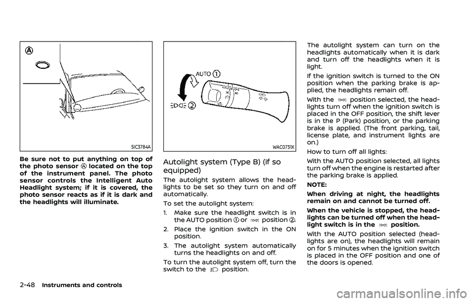
Be sure not to put anything on top of
the photo sensorlocated on the top
of the instrument panel. The photo
sensor controls the Intelligent Auto
Headlight system; if it is covered, the
photo sensor reacts as if it is dark and
the headlights will illuminate.
WAC0731X
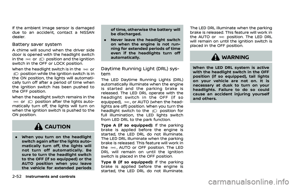
Autolight system (Type B) (if so
equipped)
The autolight system allows the head-
lights to be set so they turn on and off
automatically.
To set the autolight system:
1. Make sure the headlight switch is in the AUTO position
orposition.
2. Place the ignition switch in the ON position.
3. The autolight system automatically turns the headlights on and off.
To turn the autolight system off, turn the
switch to the
position. The autolight system can turn on the
headlights automatically when it is dark
and turn off the headlights when it is
light.
If the ignition switch is turned to the ON
position when the parking brake is ap-
plied, the headlights remain off.
With the
position selected, the head-
lights turn off when the ignition switch is
placed in the OFF position, the shift lever
is in the P (Park) position, or the parking
brake is applied. (The front parking, tail,
license plate, and instrument lights are
on.)
How to turn off all lights:
With the AUTO position selected, all lights
turn off when the engine is restarted after
the parking brake is applied.
NOTE:
When driving at night, the headlights
remain on and cannot be turned off.
When the vehicle is stopped, the head-
lights can be turned off when the head-
light switch is in the
position.
With the AUTO position selected (head-
lights are on), the headlights will remain
on for 5 minutes when the ignition switch
is placed in the OFF position and one of
the doors is opened.
Page 146 of 604

2-52Instruments and controls
If the ambient image sensor is damaged
due to an accident, contact a NISSAN
dealer.
Battery saver system
A chime will sound when the driver side
door is opened with the headlight switch
in the
orposition and the ignition
switch in the OFF or LOCK position.
When the headlight switch is in the
orposition while the ignition switch is in
the ON position, the lights will automati-
cally turn off after a period of time when
the ignition switch has been pushed to
the OFF position.
When the headlight switch remains in the
orposition after the lights auto-
matically turn off, the lights will turn on
when the ignition switch is pushed to the
ON position.
CAUTION
. When you turn on the headlight
switch again after the lights auto-
matically turn off, the lights will
not turn off automatically. Be
sure to turn the headlight switch
to the OFF (if so equipped) or the
AUTO position when you leave
the vehicle for extended periods of time, otherwise the battery will
be discharged.
. Never leave the headlight switch
on when the engine is not run-
ning for extended periods of time
even if the headlights turn off
automatically.
Daytime Running Light (DRL) sys-
tem
The LED Daytime Running Lights (DRL)
automatically illuminate when the engine
is started and the parking brake is
released. The LED DRL operate with the
headlight switch in the OFF (if so
equipped),
, or AUTO (when the head-
lights are off) position. When you turn the
headlight switch to the
position for
full illumination, the LED lights switch
from LED DRL to the park function.
Type A (if so equipped): If the parking
brake is applied before the engine is
started, the LED DRL do not illuminate.
The LED DRL illuminate when the parking
brake is released. This feature will work in
the
, AUTO or OFF position. The LED
DRL will remain on until the ignition
switch is placed in the OFF position.
Type B (if so equipped): If the parking
brake is applied before the engine is
started, the LED DRL do not illuminate. The LED DRL illuminate when the parking
brake is released. This feature will work in
the AUTO or
position. The LED DRL
will remain on until the ignition switch is
placed in the OFF position.
WARNING
When the LED DRL system is active
with the headlight switch in the OFF
position (if so equipped), tail lights
on your vehicle are not on. It is
necessary at dusk to turn on your
headlights. Failure to do so could
cause an accident injuring yourself
and others.
Page 162 of 604

2-68Instruments and controls
collision and/or emergency.
. Park the vehicle in a safe location
and set the parking brake before
operating the Emergency Call
(SOS) button.
. Only use this service in case of an
emergency. There may be a pen-
alty for inappropriate use of the
service.
. Radio waves could adversely af-
fect electric medical equipment.
Individuals who use a pacemaker
should contact the device manu-
facturer regarding any possible
effects before using the system.
. The TCU (Telematics Control Unit)
antenna is installed inside the
upper central part of the instru-
ment panel. An occupant should
not get any closer to the antenna
than specified by the pacemaker
manufacturer. The radio waves
from the TCU antenna may ad-
versely affect the operation of the
pacemaker while using the Nis-
sanConnect® Services.
WAC0510X
Making an emergency call
The Emergency Call (SOS) button is lo-
cated near the map light.
1. Push the Emergency Call (SOS) button
to make an emergency call.
2. When the line is connected, speak to the Response Specialist.
If you want to cancel the emergency call,
push and hold the Emergency Call (SOS)
button for a few seconds.
NOTE:
. After the Emergency Call (SOS) but-
ton is pushed, it may take some time
until the system initiates connec-
tion, depending on the technical environment and whether the TCU
(Telematics Control Unit) is being
used by other services.
. An indicator light on the Emergency
Call (SOS) button shows the readi-
ness of the emergency support sys-
tem. If the indicator light is not
illuminated, pushing the Emergency
Call (SOS) button does not connect
your vehicle to the Response Spe-
cialist.
The indicator light blinks while con-
nected to the NissanConnect® Ser-
vices Response Center.
. Even when the indicator light is
illuminated, connection to the Nis-
sanConnect® Services Response
Center may not be possible. If this
occurs in an emergency situation,
contact the authorities by other
means.
. To avoid disconnecting the line,
keep the engine running during an
emergency call, if it is safe to do so.
Page 208 of 604

3-20Pre-driving checks and adjustments
3. Within 5 seconds push and hold theremote engine startbutton until
the turn signal lights flash and the tail
lights illuminate. If the vehicle is not
within view, push and hold the remote
engine start
button for at least 2
seconds.
The following events will occur when the
engine starts:
. The front parking lights will turn on
and remain on as long as the engine is
running.
. The doors will be locked and the air
conditioner system may turn on.
. The engine will continue to run for
about 10 minutes. Repeat the steps to
extend the time for an additional 10
minutes. See “Extending engine run
time” (P.3-20).
Depress and hold the brake pedal, then
place the ignition switch in the ON posi-
tion before driving. For further instruc-
tions, see “Driving the vehicle” (P.5-17).
EXTENDING ENGINE RUN TIME
The remote engine start function can be
extended one time by performing the
steps listed in “Remote starting the en-
gine” (P.3-19). Run time will be calculated
as follows:
. The first 10 minute run time will start
when the remote engine start func- tion is performed.
. The second 10 minutes will start im-
mediately when the remote engine
start function is performed. For exam-
ple, if the engine has been running for
5 minutes, and 10 minutes are added,
the engine will run for a total of 15
minutes.
. Extending engine run time will count
towards the two remote engine start
limit.
A maximum of two remote engine starts,
or a single start with an extension, are
allowed between ignition cycles.
The ignition switch must be cycled to the
ON position and then back to the OFF
position before the remote engine start
procedure can be used again.
CANCELING A REMOTE ENGINE
START
To cancel a remote engine start, perform
one of the following:
. Aim the Intelligent Key at the vehicle
and push and hold the remote engine
start
button until the front park-
ing lights turn off.
. Turn on the hazard indicator flashers.
. Cycle the ignition switch ON and then
OFF. .
The extended engine run time has
expired.
. The first 10 minute timer has expired.
. The engine hood has been opened.
. The shift lever is moved out of the P
(Park) position.
. The theft alarm sounds due to illegal
entry into the vehicle.
. The ignition switch is pushed without
an Intelligent Key in the vehicle.
. The ignition switch is pushed with an
Intelligent Key in the vehicle but the
brake pedal is not depressed.
CONDITIONS THE REMOTE ENGINE
START WILL NOT WORK
The remote engine start will not operate
if any of the following conditions are
present:
.The ignition switch is placed in the ON
position.
. The hood is not securely closed.
. The hazard indicator flashers are on.
. The engine is still running. The engine
must be completely stopped. Wait at
least 6 seconds if the engine goes
from running to off. This is not applic-
able when extending engine run time.
. The remote engine start
button is
not pushed and held for at least 2
seconds.
Page 209 of 604

.The remote engine startbutton is
not pushed and held within 5 seconds
of pushing the “LOCK”
button.
. The brake pedal is depressed.
. The doors are not closed and locked.
. The liftgate is open.
. The Key System Error warning light
remains on in the vehicle information
display.
. An Intelligent Key is left inside the
vehicle.
. The theft alarm sounds due to illegal
entry into the vehicle.
. Two remote engine starts, or a single
remote engine start with an exten-
sion, have already been used.
. The shift lever is not in the P (Park)
position.
The remote engine start may display a
warning or indicator in the vehicle infor-
mation display. For an explanation of the
warning or indicator, see “Operational
indicators” (P.2-30).
WAD0267X
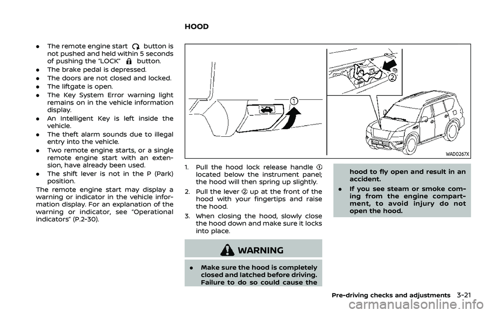
1. Pull the hood lock release handlelocated below the instrument panel;
the hood will then spring up slightly.
2. Pull the lever
up at the front of the
hood with your fingertips and raise
the hood.
3. When closing the hood, slowly close the hood down and make sure it locks
into place.
WARNING
.Make sure the hood is completely
closed and latched before driving.
Failure to do so could cause the hood to fly open and result in an
accident.
. If you see steam or smoke com-
ing from the engine compart-
ment, to avoid injury do not
open the hood.
Pre-driving checks and adjustments3-21
HOOD
Page 252 of 604

4-22Monitor, heater, air conditioner, audio, phone and voice recognition systems
Available setting items:
Setting itemAction
Display Settings Brightness Adjust display settings by touching the “+”/“-” key.
Contrast
Tint
Color
Black Level
Camera Moving Object Detection Turn the MOD system on/off. (See “Moving Object Detection (MOD)” (P.4-
31).)
Unviewable Area Reminder When this item is turned on, the unviewable area is highlighted in yellow
for several seconds after the bird’s-eye view is displayed for the first time
when the ignition switch is placed in the ON position.
Predictive Course Lines When this item is turned on, the predictive course lines are displayed in the
front, rear and bird’s-eye view screen.
Auto Show Sonar Image The automatic sonar display can be turned on/off.
NOTE:
Do not adjust any of the Intelligent Around View® Monitor settings while the vehicle is moving. Make sure the parking brake is
firmly applied.