2022 NISSAN ARMADA display
[x] Cancel search: displayPage 359 of 604
SSD1030
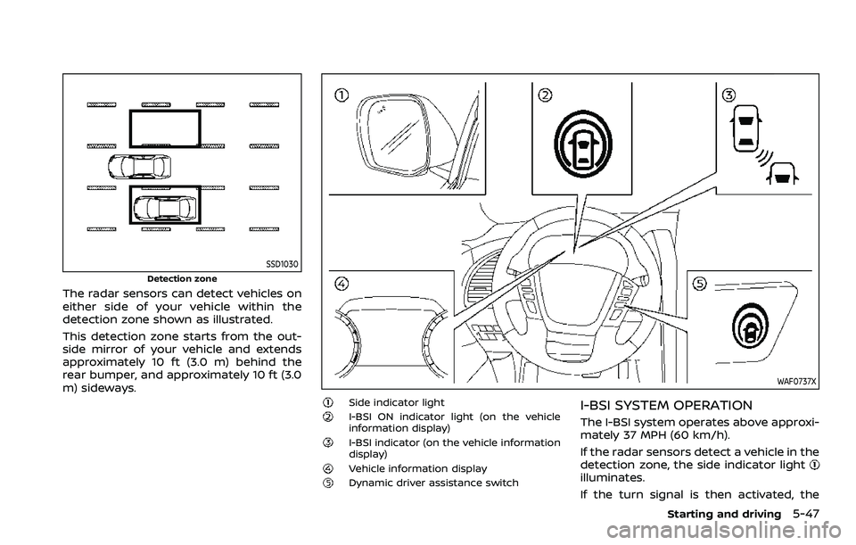
Detection zone
The radar sensors can detect vehicles on
either side of your vehicle within the
detection zone shown as illustrated.
This detection zone starts from the out-
side mirror of your vehicle and extends
approximately 10 ft (3.0 m) behind the
rear bumper, and approximately 10 ft (3.0
m) sideways.
WAF0737X
Side indicator lightI-BSI ON indicator light (on the vehicle
information display)
I-BSI indicator (on the vehicle information
display)
Vehicle information displayDynamic driver assistance switch
I-BSI SYSTEM OPERATION
The I-BSI system operates above approxi-
mately 37 MPH (60 km/h).
If the radar sensors detect a vehicle in the
detection zone, the side indicator light
illuminates.
If the turn signal is then activated, the
Starting and driving5-47
Page 360 of 604
5-48Starting and driving
system chimes (twice) and the side in-
dicator light flashes. The side indicator
light continues to flash until the detected
vehicle leaves the detection zone.
If the I-BSI system is ON and your vehicle
approaches a lane marker while another
vehicle is in the detection zone, the
system chimes (three times) and the side
indicator light flashes. Then the I-BSI
system slightly applies the brakes to help
return the vehicle back to the center of
the driving lane. The I-BSI system oper-
ates regardless of turn signal usage.
NOTE:
.I-BSI warning and system applica-
tion will only be activated if the side
indicator light is already illuminated
when your vehicle approaches a
lane marker. If another vehicle
comes into the detection zone after
your vehicle has crossed a lane
marker, no I-BSI warning or system
application will be activated. (See “I-
BSI driving situations” (P.5-51).)
. The I-BSI system is typically acti-
vated earlier than the Intelligent
Lane Intervention (I-LI) system when
your vehicle is approaching a lane
marker.
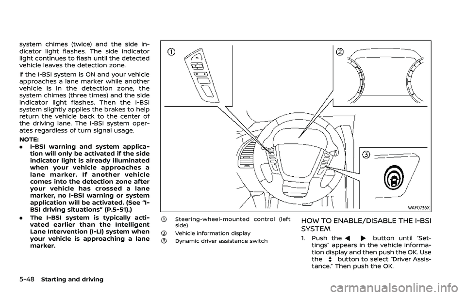
WAF0736X
Steering-wheel-mounted control (left
side)
Vehicle information displayDynamic driver assistance switch
HOW TO ENABLE/DISABLE THE I-BSI
SYSTEM
1. Push thebutton until “Set-
tings” appears in the vehicle informa-
tion display and then push the OK. Use
the
button to select “Driver Assis-
tance.” Then push the OK.
Page 361 of 604
2. Select “Blind Spot” and push the OK.
3. Select “Intervention (BSI)” and pushthe OK.
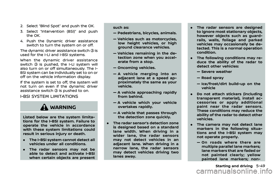
4. Push the Dynamic driver assistance switch to turn the system on or off.
The dynamic driver assistance switch
is
used for the I-LI and I-BSI systems.
When the dynamic driver assistance
switch
is pushed, the I-LI system will
also turn on or off simultaneously. The I-
BSI system can be individually set to on or
off on the vehicle information display.
If the system is set to off, the system will
not turn on even if the dynamic driver
assistance switch
is pushed to on.
I-BSI SYSTEM LIMITATIONS
WARNING
Listed below are the system limita-
tions for the I-BSI system. Failure to
operate the vehicle in accordance
with these system limitations could
result in serious injury or death.
. The I-BSI system cannot detect all
vehicles under all conditions.
. The radar sensors may not be
able to detect and activate I-BSI
when certain objects are present such as:
— Pedestrians, bicycles, animals.
— Vehicles such as motorcycles,
low height vehicles, or high
ground clearance vehicles.
— Vehicles remaining in the de- tection zone when you accel-
erate from a stop.
— Oncoming vehicles.
— A vehicle merging into an adjacent lane at a speed ap-
proximately the same as your
vehicle.
— A vehicle approaching rapidly from behind.
— A vehicle which your vehicle overtakes rapidly.
— A vehicle that passes through the detection zone quickly.
. The radar sensor’s detection zone
is designed based on a standard
lane width. When driving in a
wider lane, the radar sensors
may not detect vehicles in an
adjacent lane. When driving in a
narrow lane, the radar sensors
may detect vehicles driving two
lanes away. .
The radar sensors are designed
to ignore most stationary objects,
however objects such as guard-
rails, walls, foliage and parked
vehicles may occasionally be de-
tected. This is a normal operation
condition.
. The following conditions may re-
duce the ability of the radar to
detect other vehicles:
— Severe weather
— Road spray
— Ice/frost/dirt build-up on the
vehicle
. Do not attach stickers (including
transparent material), install ac-
cessories or apply additional
paint near the radar sensors.
These conditions may reduce the
ability of the radar to detect other
vehicles.
. The camera may not detect lane
markers in the following situa-
tions and the I-BSI system may
not operate properly.
— On roads where there are
multiple parallel lane markers;
lane markers that are faded or
not painted clearly; yellow
painted lane markers; non-
Starting and driving5-49
Page 366 of 604

5-54Starting and driving
JVS0761X
Illustration 9 - Entering from the side
Illustration 9: If the I-BSI system is on and
your vehicle approaches the lane marker
while another vehicle is in the detection
zone, the system chimes (three times)
and the side indicator light flashes. The I-
BSI system activates to help return the
vehicle back to the center of the driving
lane.
JVS0742X
Illustration 10 - Entering from the side
Illustration 10: The I-BSI system will not
operate if your vehicle is on a lane marker
when another vehicle enters the detec-
tion zone. In this case only the BSW
system operates.
NOTE:
.The radar sensors may not detect a
vehicle which is traveling at about
the same speed as your vehicle
when it enters the detection zone.
. I-BSI will not operate or will stop
operating and only a warning chime
will sound under the following con-
ditions. —
When the brake pedal is de-
pressed.
— When the vehicle is accelerated
during I-BSI system operation
— When steering quickly
— When the ICC, I-FCW or AEB warn-
ings sound.
— When the hazard warning flashers
are operated.
— When driving on a curve at a high
speed.
— When the BSW system is turned
off.
SYSTEM TEMPORARILY UNAVAIL-
ABLE
When any of the following messages
appear on the vehicle information display,
a chime will sound and the I-BSI system
will be turned off automatically.
. “Not Available: Poor Road Conditions”:
When the VDC system (except traction
control system function) or ABS oper-
ates.
. “Currently unavailable/Currently not
available”:
— When the VDC system is turned off.
— When the SNOW mode is selected.
— When the 4WD shift switch is in the
4H or 4L position. (4WD models)
Page 367 of 604
.“Not Available: High Camera Temp”:
If the vehicle is parked in direct sun-
light under high temperature condi-
tions (over approximately 104°F
(40°C)).
. “Unavailable Side Radar Obstruction”:
When side radar blockage is detected.
Turn off the I-BSI system and turn it on
again when the above conditions no
longer exist.
SYSTEM MALFUNCTION
When the I-BSI system malfunctions, it will
be turned off automatically, the I-BSI
indicator illuminates and a chime will
sound, and the “Malfunction” warning
message will appear in the vehicle infor-
mation display.
Action to take:
Stop the vehicle in a safe location and
push the park button to engage the P
(Park) position. Turn the engine off and
restart the engine. If the warning mes-
sage continues to appear, It is recom-
mended you visit a NISSAN dealer for this
service.
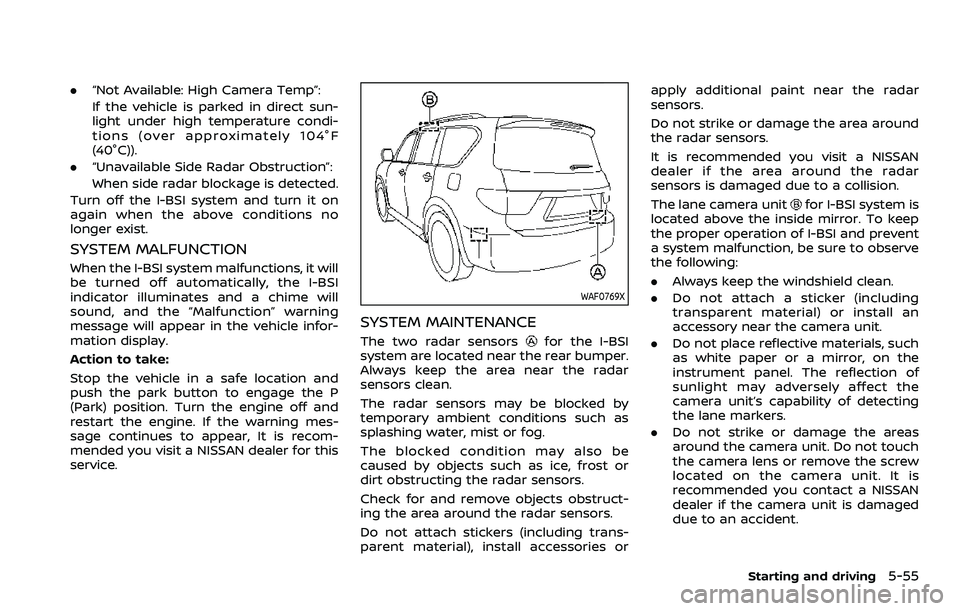
WAF0769X
SYSTEM MAINTENANCE
The two radar sensorsfor the I-BSI
system are located near the rear bumper.
Always keep the area near the radar
sensors clean.
The radar sensors may be blocked by
temporary ambient conditions such as
splashing water, mist or fog.
The blocked condition may also be
caused by objects such as ice, frost or
dirt obstructing the radar sensors.
Check for and remove objects obstruct-
ing the area around the radar sensors.
Do not attach stickers (including trans-
parent material), install accessories or apply additional paint near the radar
sensors.
Do not strike or damage the area around
the radar sensors.
It is recommended you visit a NISSAN
dealer if the area around the radar
sensors is damaged due to a collision.
The lane camera unit
for I-BSI system is
located above the inside mirror. To keep
the proper operation of I-BSI and prevent
a system malfunction, be sure to observe
the following:
. Always keep the windshield clean.
. Do not attach a sticker (including
transparent material) or install an
accessory near the camera unit.
. Do not place reflective materials, such
as white paper or a mirror, on the
instrument panel. The reflection of
sunlight may adversely affect the
camera unit’s capability of detecting
the lane markers.
. Do not strike or damage the areas
around the camera unit. Do not touch
the camera lens or remove the screw
located on the camera unit. It is
recommended you contact a NISSAN
dealer if the camera unit is damaged
due to an accident.
Starting and driving5-55
Page 369 of 604
WARNING
Failure to follow the warnings and
instructions for proper use of the
RCTA system could result in serious
injury or death.
.The RCTA system is not a replace-
ment for proper driving proce-
dures and is not designed to
prevent contact with vehicles or
objects. When backing out of a
parking space, always use the
side and rear mirrors and turn
and look in the direction your
vehicle will move. Never rely so-
lely on the RCTA system.
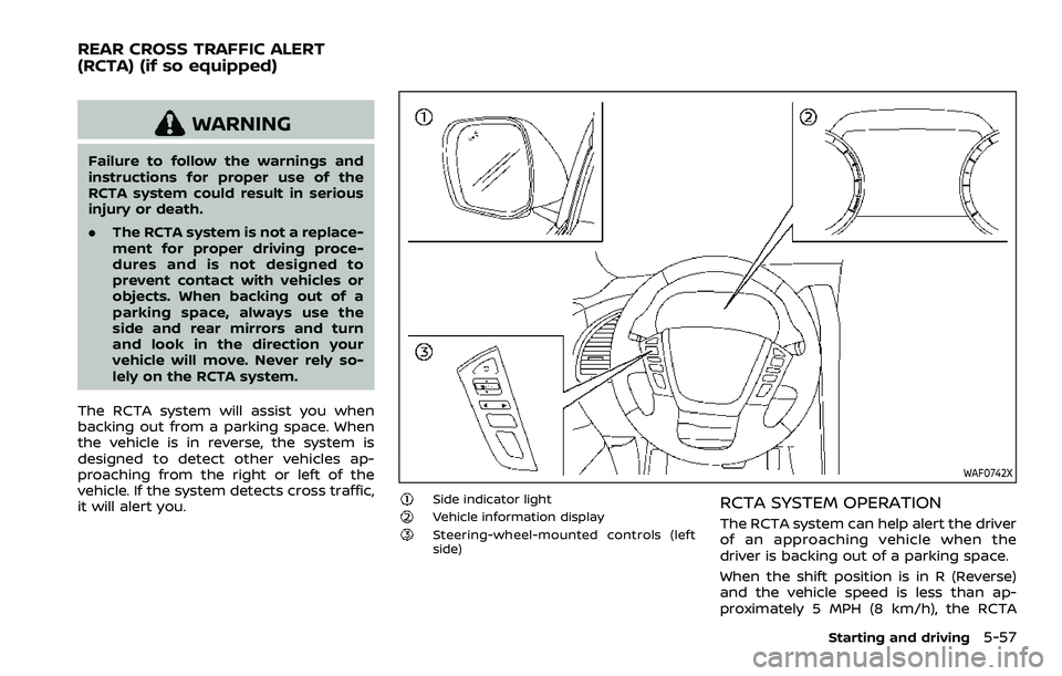
The RCTA system will assist you when
backing out from a parking space. When
the vehicle is in reverse, the system is
designed to detect other vehicles ap-
proaching from the right or left of the
vehicle. If the system detects cross traffic,
it will alert you.
WAF0742X
Side indicator lightVehicle information displaySteering-wheel-mounted controls (left
side)
RCTA SYSTEM OPERATION
The RCTA system can help alert the driver
of an approaching vehicle when the
driver is backing out of a parking space.
When the shift position is in R (Reverse)
and the vehicle speed is less than ap-
proximately 5 MPH (8 km/h), the RCTA
Starting and driving5-57
REAR CROSS TRAFFIC ALERT
(RCTA) (if so equipped)
Page 371 of 604
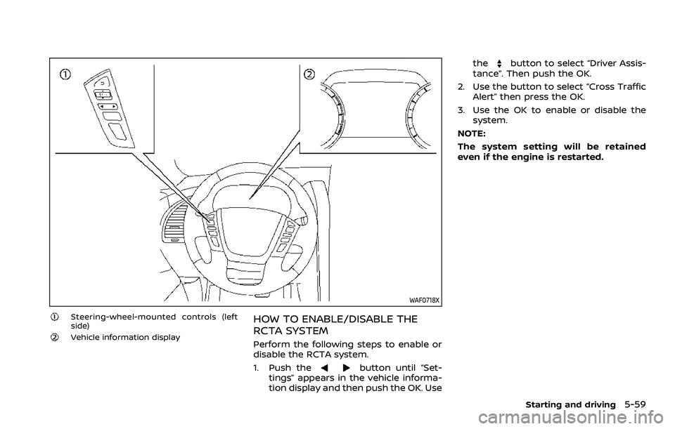
WAF0718X
Steering-wheel-mounted controls (left
side)
Vehicle information display
HOW TO ENABLE/DISABLE THE
RCTA SYSTEM
Perform the following steps to enable or
disable the RCTA system.
1. Push the
button until “Set-
tings” appears in the vehicle informa-
tion display and then push the OK. Use the
button to select “Driver Assis-
tance”. Then push the OK.
2. Use the button to select “Cross Traffic Alert” then press the OK.
3. Use the OK to enable or disable the system.
NOTE:
The system setting will be retained
even if the engine is restarted.
Starting and driving5-59
Page 374 of 604
5-62Starting and driving
NOTE:
In the case of several vehicles ap-
proaching in a row (Illustration 1) or in
the opposite direction (Illustration 2), a
chime may not be sounded by the RCTA
system after the first vehicle passes the
sensors.
SYSTEM TEMPORARILY UNAVAIL-
ABLE
When radar blockage is detected, the
system will be deactivated automatically.
The “Unavailable Side Radar Obstruction”
warning message will appear in the
vehicle information display.
The systems are not available until the
conditions no longer exist.
The radar sensors may be blocked by
temporary ambient conditions such as
splashing water, mist or fog.
The blocked condition may also be
caused by objects such as ice, frost or
dirt obstructing the radar sensors.
NOTE:
If the BSW system stops working, the
RCTA and Intelligent Blind Spot Inter-
vention (I-BSI) systems will also stop
working.
Action to take:
When the above conditions no longer
exist, the system will resume automati-cally.
SYSTEM MALFUNCTION
When the RCTA system malfunctions, it
will turn off automatically. The “Malfunc-
tion” warning message will appear in the
vehicle information display.
NOTE:
If the BSW system stops working, the
RCTA and I-BSI systems will also stop
working.
Action to take:
Stop the vehicle in a safe location, turn
the engine off and restart the engine. If
the message continues to appear, have
the system checked. It is recommended
that you visit a NISSAN dealer for this
service.
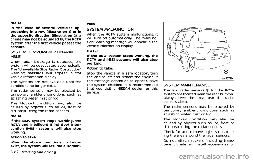
WAF0721X
SYSTEM MAINTENANCE
The two radar sensorsfor the RCTA
system are located near the rear bumper.
Always keep the area near the radar
sensors clean.
The radar sensors may be blocked by
temporary ambient conditions such as
splashing water, mist or fog.
The blocked condition may also be
caused by objects such as ice, frost or
dirt obstructing the radar sensors.
Check for and remove objects obstruct-
ing the area around the radar sensors.
Do not attach stickers (including trans-
parent material), install accessories or