2022 LINCOLN CORSAIR boot
[x] Cancel search: bootPage 249 of 676
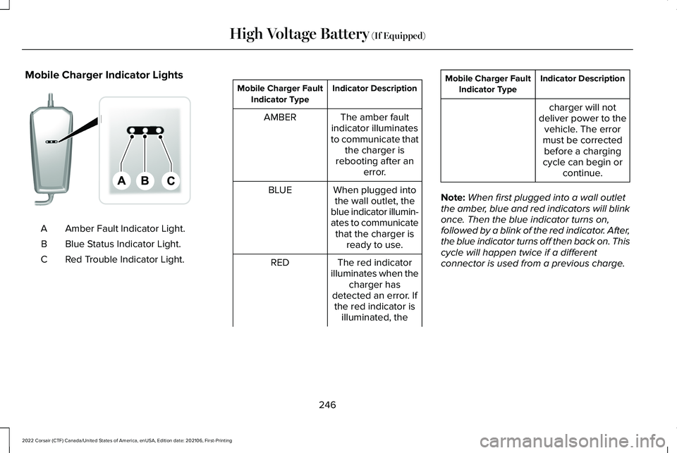
Mobile Charger Indicator Lights
Amber Fault Indicator Light.
A
Blue Status Indicator Light.
B
Red Trouble Indicator Light.
C Indicator Description
Mobile Charger Fault
Indicator Type
The amber fault
indicator illuminates
to communicate that the charger is
rebooting after an error.
AMBER
When plugged intothe wall outlet, the
blue indicator illumin-
ates to communicate that the charger is ready to use.
BLUE
The red indicator
illuminates when the charger has
detected an error. If the red indicator is illuminated, the
RED Indicator Description
Mobile Charger Fault
Indicator Type
charger will not
deliver power to the vehicle. The error
must be corrected before a charging
cycle can begin or continue.
Note: When first plugged into a wall outlet
the amber, blue and red indicators will blink
once. Then the blue indicator turns on,
followed by a blink of the red indicator. After,
the blue indicator turns off then back on. This
cycle will happen twice if a different
connector is used from a previous charge.
246
2022 Corsair (CTF) Canada/United States of America, enUSA, Edition date: 202106, First-Printing High Voltage Battery (If Equipped)E336515
Page 251 of 676
ACTION
MODE
RED
BLUE
AMBER
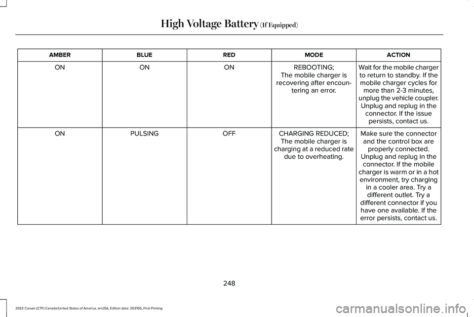
Wait for the mobile chargerto return to standby. If themobile charger cycles for more than 2-3 minutes,
unplug the vehicle coupler. Unplug and replug in the connector. If the issuepersists, contact us.
REBOOTING;
The mobile charger is
recovering after encoun- tering an error.
ON
ON
ON
Make sure the connectorand the control box are properly connected.
Unplug and replug in the connector. If the mobile
charger is warm or in a hot
CHARGING REDUCED;
The mobile charger is
charging at a reduced rate due to overheating.
OFF
PULSING
ON
environment, try chargingin a cooler area. Try adifferent outlet. Try a
different connector if you have one available. If the
error persists, contact us.
248
2022 Corsair (CTF) Canada/United States of America, enUSA, Edition date: 202106, First-Printing High Voltage Battery (If Equipped)
Page 368 of 676
Preparing Your Vehicle
Note:
Use only a 12 volt supply to start your
vehicle.
Park the booster vehicle close to the hood
of the disabled vehicle, making sure the two
vehicles do not touch.
Connecting the Jumper Cables WARNING: Do not connect the
negative jumper cable to any other part of
your vehicle. Use the ground point.
Note: If you are using a jump pack or booster
box, follow that manufacturer's instructions.
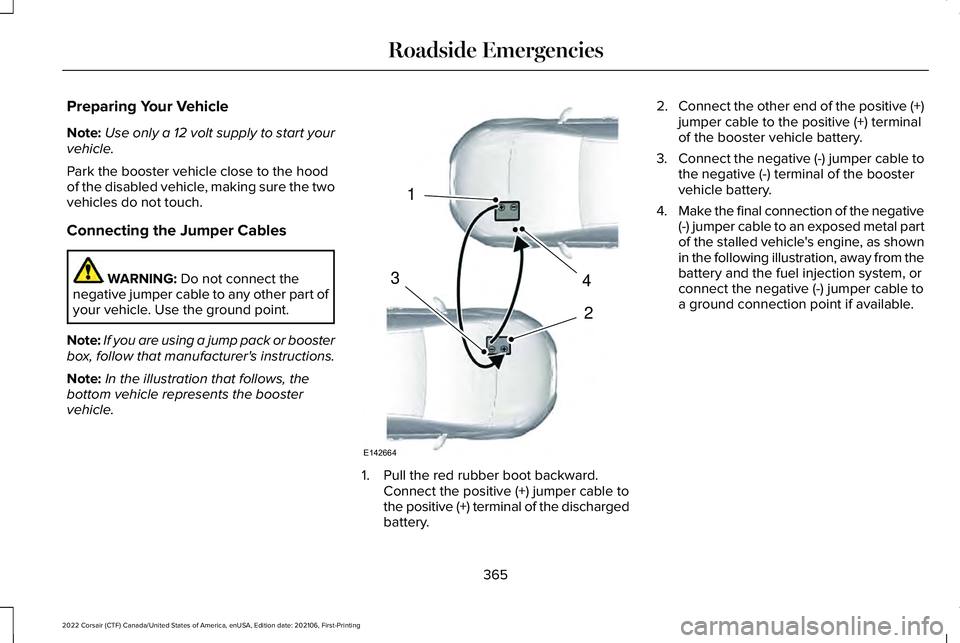
Note: In the illustration that follows, the
bottom vehicle represents the booster
vehicle. 1. Pull the red rubber boot backward.
Connect the positive (+) jumper cable to
the positive (+) terminal of the discharged
battery. 2.
Connect the other end of the positive (+)
jumper cable to the positive (+) terminal
of the booster vehicle battery.
3. Connect the negative (-) jumper cable to
the negative (-) terminal of the booster
vehicle battery.
4. Make the final connection of the negative
(-) jumper cable to an exposed metal part
of the stalled vehicle's engine, as shown
in the following illustration, away from the
battery and the fuel injection system, or
connect the negative (-) jumper cable to
a ground connection point if available.
365
2022 Corsair (CTF) Canada/United States of America, enUSA, Edition date: 202106, First-Printing Roadside Emergencies4
2
1
3
E142664
Page 401 of 676
When changing the air filter element, use
only parts that meet or exceed our
specifications.
When servicing the air cleaner on vehicles
with a turbocharger, it is important that no
foreign material enter the air induction
system. The engine and turbocharger are
susceptible to damage from even small
particles.
Change the air filter element at the proper
interval. See Normal Scheduled
Maintenance (page 584).
Note: Failure to use the correct air filter
element may result in severe engine
damage. The customer warranty may be
void for any damage to the engine if the
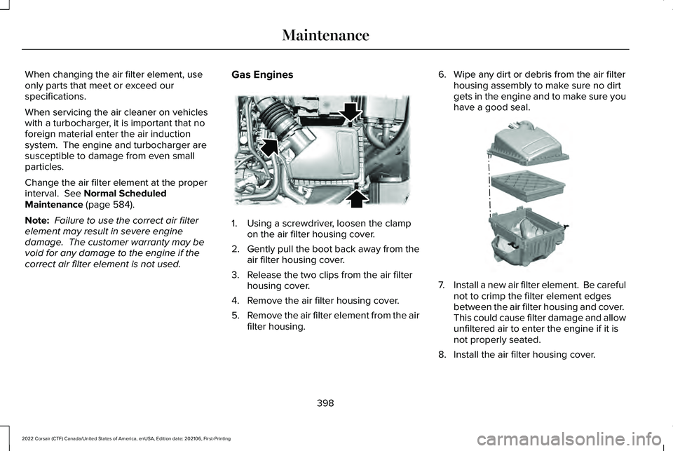
correct air filter element is not used. Gas Engines 1. Using a screwdriver, loosen the clamp
on the air filter housing cover.
2. Gently pull the boot back away from the
air filter housing cover.
3. Release the two clips from the air filter housing cover.
4. Remove the air filter housing cover.
5. Remove the air filter element from the air
filter housing. 6. Wipe any dirt or debris from the air filter
housing assembly to make sure no dirt
gets in the engine and to make sure you
have a good seal. 7.
Install a new air filter element. Be careful
not to crimp the filter element edges
between the air filter housing and cover.
This could cause filter damage and allow
unfiltered air to enter the engine if it is
not properly seated.
8. Install the air filter housing cover.
398
2022 Corsair (CTF) Canada/United States of America, enUSA, Edition date: 202106, First-Printing MaintenanceE299070 E299073
Page 402 of 676
9. Engage the clips to secure the air filter
housing cover to the air filter housing.
10. Reconnect the boot to the air filter housing cover and tighten securely.
CHANGING THE ENGINE AIR
FILTER - 2.5L, PLUG-IN HYBRID
ELECTRIC VEHICLE (PHEV) WARNING: To reduce the risk of
vehicle damage and personal burn injuries,
do not start your engine with the air
cleaner removed and do not remove it
while the engine is running.
When changing the air filter element, use
only parts that meet or exceed our
specifications.
Change the air filter element at the proper
interval. See Scheduled Maintenance (page
579
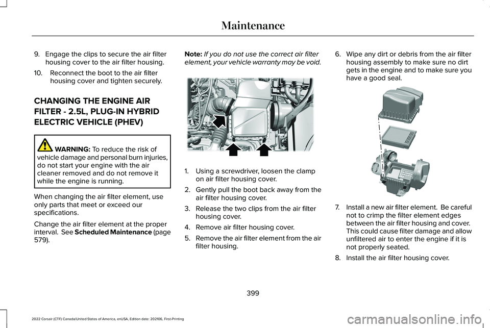
). Note:
If you do not use the correct air filter
element, your vehicle warranty may be void. 1. Using a screwdriver, loosen the clamp
on air filter housing cover.
2. Gently pull the boot back away from the
air filter housing cover.
3. Release the two clips from the air filter housing cover.
4. Remove air filter housing cover.
5. Remove the air filter element from the air
filter housing. 6. Wipe any dirt or debris from the air filter
housing assembly to make sure no dirt
gets in the engine and to make sure you
have a good seal. 7.
Install a new air filter element. Be careful
not to crimp the filter element edges
between the air filter housing and cover.
This could cause filter damage and allow
unfiltered air to enter the engine if it is
not properly seated.
8. Install the air filter housing cover.
399
2022 Corsair (CTF) Canada/United States of America, enUSA, Edition date: 202106, First-Printing MaintenanceE299071 E299074
Page 403 of 676

9. Engage the clips to secure the air filter
housing cover to the air filter housing.
10. Reconnect the boot to the air filter housing cover and tighten securely.
ENGINE COOLANT CHECK WARNING: Do not remove the
coolant reservoir cap when the engine is
on or the cooling system is hot. Wait 10
minutes for the cooling system to cool
down. Cover the coolant reservoir cap with
a thick cloth to prevent the possibility of
scalding and slowly remove the cap.
Failure to follow this instruction could result
in personal injury. WARNING: Do not put coolant in the
windshield washer reservoir. If sprayed on
the windshield, coolant could make it
difficult to see through the windshield. WARNING:
To reduce the risk of
personal injury, make sure the engine is
cool before unscrewing the coolant
pressure relief cap. The cooling system is
under pressure. Steam and hot liquid can
come out forcefully when you loosen the
cap slightly. WARNING:
Do not add coolant
further than the MAX mark.
When the engine is cold, check the
concentration and level of the coolant at the
intervals listed in the scheduled maintenance
information.
See Scheduled Maintenance
(page 579).
Note: Make sure that the coolant level is
between the
MIN and the MAX marks on
the coolant reservoir.
Note: Coolant expands when it is hot. The
level may extend beyond the
MAX mark. Maintain coolant concentration within 48%
to 50%, which equates to a freeze point
between
-29°F (-34°C) and -35°F (-37°C).
Coolant concentration should be checked
using a refractometer. We do not recommend
the use of hydrometers or coolant test strips
for measuring coolant concentration.
Adding Coolant WARNING:
Do not remove the
coolant reservoir cap when the engine is
on or the cooling system is hot. Wait 10
minutes for the cooling system to cool
down. Cover the coolant reservoir cap with
a thick cloth to prevent the possibility of
scalding and slowly remove the cap.
Failure to follow this instruction could result
in personal injury. WARNING:
Do not add engine
coolant when the engine is on or the
cooling system is hot. Failure to follow this
instruction could result in personal injury.
400
2022 Corsair (CTF) Canada/United States of America, enUSA, Edition date: 202106, First-Printing Maintenance
Page 586 of 676

Multi-Point Inspection
Hazard warning system operation
Accessory drive belt(s)
Horn operation
Battery performance
Radiator, cooler, heater and air conditioning hoses
Engine air filter
Suspension components for leaks or damage
Exhaust system
Steering and linkage
Exterior lamps operation
Tires (including spare) for wear and proper pressure2
Fluid levels 1
; fill if necessary
Windshield for cracks, chips or pits
For oil and fluid leaks
Washer spray and wiper operation
Half-shaft dust boots
1 Brake, coolant recovery reservoir, automatic transmission and window washer.
2 If your vehicle comes with a temporary mobility kit, check the tire seal\
ant expiration Use By date on the canister. Replace as needed.
Be sure to ask your dealership service
advisor or technician about the multi-point
vehicle inspection. It is a comprehensive way
to perform a thorough inspection of your
vehicle. Your checklist gives you immediate
feedback on the overall condition of your
vehicle.
583
2022 Corsair (CTF) Canada/United States of America, enUSA, Edition date: 202106, First-Printing Scheduled Maintenance
Page 589 of 676

At Every Oil Change Interval as Indicated by the Information Display
1
Inspect the exhaust system and heat shields.
Inspect the rear axle and U-joints for all-wheel drive vehicles.
Inspect the half-shaft boots.
Inspect the steering linkage, ball joints, suspension, tie-rod ends, driveshaft and the U-joints.
Inspect the tires, tire wear and measure the tread depth.
Inspect the wheels and related components for abnormal noise, wear, looseness or drag.
1 Do not exceed one year or 10,000 mi (16,000 km) between service intervals.
2 Reset the Intelligent Oil-Life Monitor after engine oil and filter change\
s.
See Oil Change Indicator Reset (page 397). Brake Fluid Maintenance
1
Change the brake fluid. 2
Every Three Years
1 Perform this maintenance item every three years. Do not exceed the designated time for the interval.
2 Brake fluid servicing requires special equipment available at your authorize\
d dealer.
586
2022 Corsair (CTF) Canada/United States of America, enUSA, Edition date: 202106, First-Printing Scheduled Maintenance