Page 350 of 446

6-23
What to do in an emergency
6
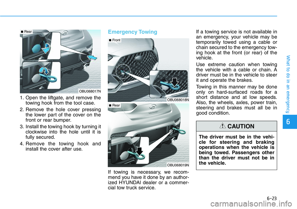
1. Open the liftgate, and remove the
towing hook from the tool case.
2. Remove the hole cover pressing
the lower part of the cover on the
front or rear bumper.
3. Install the towing hook by turning it
clockwise into the hole until it is
fully secured.
4. Remove the towing hook and
install the cover after use.
Emergency Towing
If towing is necessary, we recom-
mend you have it done by an author-
ized HYUNDAI dealer or a commer-
cial tow truck service.If a towing service is not available in
an emergency, your vehicle may be
temporarily towed using a cable or
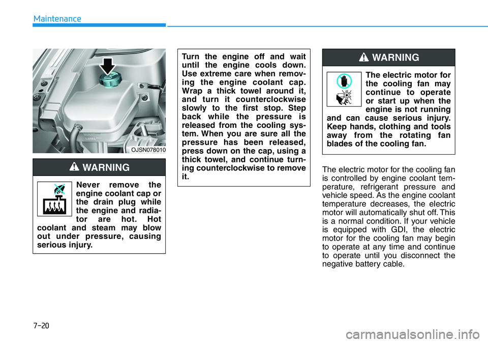
chain secured to the emergency tow-
ing hook at the front (or rear) of the
vehicle.
Use extreme caution when towing
the vehicle with a cable or chain. A
driver must be in the vehicle to steer
it and operate the brakes.
Towing in this manner may be done
only on hard-surfaced roads for a
short distance and at low speeds.
Also, the wheels, axles, power train,
steering and brakes must all be in
good condition.
OBU068017N
■Rear
OBU068018N
OBU068019N
■Front
■Rear
The driver must be in the vehi-
cle for steering and braking
operations when the vehicle is
being towed. Passengers other
than the driver must not be in
the vehicle.
CAUTION
Page 372 of 446

7-20
Maintenance
The electric motor for the cooling fan
is controlled by engine coolant tem-
perature, refrigerant pressure and
vehicle speed. As the engine coolant
temperature decreases, the electric
motor will automatically shut off. This
is a normal condition. If your vehicle
is equipped with GDI, the electric
motor for the cooling fan may begin
to operate at any time and continue
to operate until you disconnect the
negative battery cable.The electric motor for
the cooling fan may
continue to operate
or start up when the
engine is not running
and can cause serious injury.
Keep hands, clothing and tools
away from the rotating fan
blades of the cooling fan.
WARNING
Never remove the
engine coolant cap or
the drain plug while
the engine and radia-
tor are hot. Hot
coolant and steam may blow
out under pressure, causing
serious injury.
WARNING
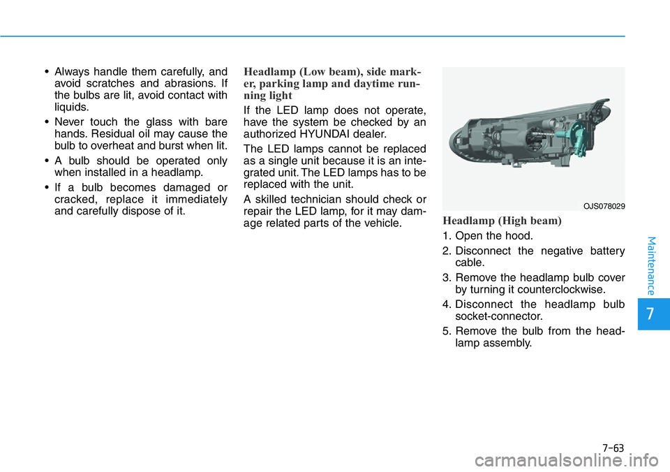
OJSN078010
Turn the engine off and wait
until the engine cools down.
Use extreme care when remov-
ing the engine coolant cap.
Wrap a thick towel around it,
and turn it counterclockwise
slowly to the first stop. Step
back while the pressure is
released from the cooling sys-
tem. When you are sure all the
pressure has been released,
press down on the cap, using a
thick towel, and continue turn-
ing counterclockwise to remove
it.
Page 383 of 446

7-31
7
Maintenance
By jump starting
After a jump start from a good bat-
tery, drive the vehicle for 20-30 min-
utes before it is shutoff. The vehicle
may not restart if you shut it off
before the battery had a chance to
adequately recharge. See "Jump
Starting" in chapter 6 for more details
on jump starting procedures.
Information
An inappropriately disposed
battery can be harmful to
the environment and human
health. Dispose of the bat-
tery according to your local
law(s) or regulations.
Reset Features
The following items may need to be
reset after the battery has been dis-
charged or the battery has been dis-
connected. See chapter 3 or 4 for:
• Power Windows
• Trip Computer
• Climate Control System
• Clock
• Audio System
i
•Watch the battery during
charging, and stop or reduce
the charging rate if the battery
cells begin boiling violently.
•The negative battery cable
must be removed first and
installed last when the battery
is disconnected. Disconnect
the battery charger in the fol-
lowing order:
(1) Turn off the battery charg-
er main switch.
(2) Unhook the negative
clamp from the negative
battery terminal.
(3) Unhook the positive clamp
from the positive battery
terminal.
•
Always use a genuine
HYUNDAI approved battery
when you replace the battery.
Page 401 of 446
7-49
7
Maintenance
Fuse switch
Always, place the fuse switch to the
ON position.
If you move the switch to the OFF
position, some items such as the
audio system and digital clock must
be reset and the smart key may not
work properly.
Information
If the fuse switch is OFF, the above
message will appear.
• Always place the fuse switch in
the ON position while driving the
vehicle.
• Do not move the fuse switch
repeatedly. The fuse switch may
be damaged.
Engine Compartment Panel
Fuse Replacement
1. Turn the engine off.
2. Turn all other switches OFF.
NOTICE
i
OJSN078023OOS047142L
OJSN078077
OJSN078078
■Blade type fuse
■Cartridge type fuse
Page 415 of 446

7-63
7
Maintenance
• Always handle them carefully, and
avoid scratches and abrasions. If
the bulbs are lit, avoid contact with
liquids.
• Never touch the glass with bare
hands. Residual oil may cause the
bulb to overheat and burst when lit.
• A bulb should be operated only
when installed in a headlamp.
• If a bulb becomes damaged or
cracked, replace it immediately
and carefully dispose of it.Headlamp (Low beam), side mark-
er, parking lamp and daytime run-
ning light
If the LED lamp does not operate,
have the system be checked by an
authorized HYUNDAI dealer.
The LED lamps cannot be replaced
as a single unit because it is an inte-
grated unit. The LED lamps has to be
replaced with the unit.
A skilled technician should check or
repair the LED lamp, for it may dam-
age related parts of the vehicle.
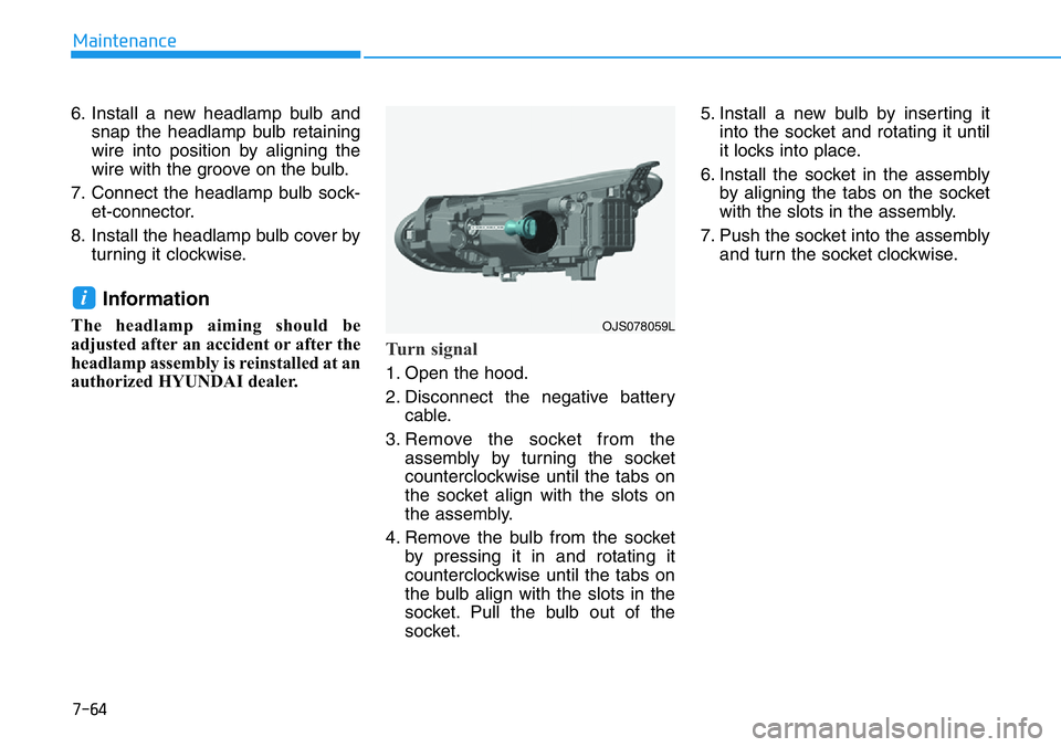
Headlamp (High beam)
1. Open the hood.
2. Disconnect the negative battery
cable.
3. Remove the headlamp bulb cover
by turning it counterclockwise.
4. Disconnect the headlamp bulb
socket-connector.
5. Remove the bulb from the head-
lamp assembly.
OJS078029
Page 416 of 446

7-64
Maintenance
6. Install a new headlamp bulb and
snap the headlamp bulb retaining
wire into position by aligning the
wire with the groove on the bulb.
7. Connect the headlamp bulb sock-
et-connector.
8. Install the headlamp bulb cover by
turning it clockwise.
Information
The headlamp aiming should be
adjusted after an accident or after the
headlamp assembly is reinstalled at an
authorized HYUNDAI dealer.
Turn signal
1. Open the hood.
2. Disconnect the negative battery
cable.
3. Remove the socket from the
assembly by turning the socket
counterclockwise until the tabs on
the socket align with the slots on
the assembly.
4. Remove the bulb from the socket
by pressing it in and rotating it
counterclockwise until the tabs on
the bulb align with the slots in the
socket. Pull the bulb out of the
socket.5. Install a new bulb by inserting it
into the socket and rotating it until
it locks into place.
6. Install the socket in the assembly
by aligning the tabs on the socket
with the slots in the assembly.
7. Push the socket into the assembly
and turn the socket clockwise.
i
OJS078059L
Page 418 of 446
7-66
Maintenance
Turn signal lamp
1. Open the liftgate.
2. Open the lamp assembly retaining
screw covers.
3. Loosen the lamp assembly retain-
ing screws with a cross-tip screw-
driver.4. Remove the rear combination
lamp assembly from the body of
the vehicle.
5. Remove the socket from the
assembly by turning the socket
counterclockwise until the tabs on
the socket align with the slots on
the assembly.
[A] : Turn signal lamp
6. Remove the bulb from the socket
by pressing it in and rotating it
counterclockwise until the tabs on
the bulb align with the slots in the
socket. Pull the bulb out of the
socket.
7. Insert a new bulb by inserting it
into the socket and rotating it until
it locks into place.
8. Install the socket into the assem-
bly by aligning the tabs on the
socket with the slots in the assem-
bly. Push the socket into the
assembly and turn the socket
clockwise.
9. Reinstall the lamp assembly to the
body of the vehicle.
OJSN078036LOJS078033OJS078032
Page 419 of 446
7-67
7
Maintenance
Backup lamp
1. Turn off the engine.
2. Open the liftgate.
3. Remove the service cover using a
flat-blade screwdriver.
[A] : Backup lamp
4. Remove the socket from the
assembly by turning the socket
counterclockwise until the tabs on
the socket align with the slots on
the assembly.
5. Remove the bulb from the socket
by pressing it in and rotating it
counterclockwise until the tabs on
the bulb align with the slots in the
socket. Pull the bulb out of the
socket.6. Insert a new bulb by inserting it
into the socket and rotating it until
it locks into place.
7. Install the socket into the assem-
bly by aligning the tabs on the
socket with the slots in the assem-
bly. Push the socket into the
assembly and turn the socket
clockwise.
8. Reinstall the lamp assembly to the
body of the vehicle.
OJS078034OJSN078038L