2022 HYUNDAI SONATA tow
[x] Cancel search: towPage 224 of 546
Convenient Features
5-94
• Outside air temperature is hot or cold.
• The wind is either strong (over 12 mph
(20 km/h)) or blowing perpendicular
to the rear bumper.
• Objects generating excessive
noise, such as vehicle horns, loud
motorcycle engines, or truck air
brakes, are near the vehicle.
• An ultrasonic sensor with a similar
frequency is near the vehicle.
• There is ground height difference
between the vehicle and the
pedestrian.
• The image of the pedestrian in the
rear view camera is indistinguishable
from the background.
• The pedestrian is near the rear edge of
the vehicle.
• The pedestrian is not standing upright.
• The pedestrian is either too short or
too tall for the system to recognize.
• The pedestrian is wearing clothes that
are hard for the system to recognize.
• The pedestrian is wearing a cloth that
does not reflect ultrasound well.
• The size, thickness, height, or shape of
the object does not reflect ultrasound
well (e.g., pole, bush, curbs, carts,
edge of a wall, etc.).
• The pedestrian or the object is
moving.
• The pedestrian or the object is very
close to the rear of the vehicle.
• A wall is behind the pedestrian or the
object.
• The object is not at the rear center of
the vehicle.
• The plane of the obstacle is not
parallel to the rear bumper.
• The road is slippery or inclined.
• The driver backs up the vehicle
immediately after shifting to R
(Reverse).
• The driver accelerates or turns the
vehicle. Reverse Parking Collision-Avoidance
Assist system may alert the driver or
apply brake power unnecessarily under
the following conditions even if there are
“no” pedestrians or objects.
•
Any non-factory equipment or
accessories have been installed.
• The condition of the vehicle is
unstable due to an accident or other
causes.
• The height of the bumper or the
sensor installation has been modified.
• The bumper height has changed due
to heavy loads, tire pressure change,
etc.
• The rear view camera or the ultrasonic
sensor(s) is stained with foreign
matter, such as snow, dirt, etc.
• The pattern on the road is mistaken
for a pedestrian.
• There is a shadow or a light reflecting
on the ground.
• Pedestrians or objects are around the
path of the vehicle.
• Objects generating excessive
noise, such as vehicle horns, loud
motorcycle engines, or truck air
brakes, are near the vehicle.
• The vehicle is backing towards a
narrow passage or parking space.
• The vehicle is backing towards an
uneven road surface, such as unpaved
road, gravel, bump, gradient, etc.
• A trailer is attached to the vehicle
Page 251 of 546
05
5-121
ODN8059106
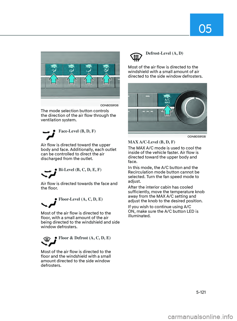
The mode selection button controls
the direction of the air flow through the
ventilation system.
Face-Level (B, D, F)
Air flow is directed toward the upper
body and face. Additionally, each outlet
can be controlled to direct the air
discharged from the outlet.
Bi-Level (B, C, D, E, F)
Air flow is directed towards the face and
the floor.
Floor-Level (A, C, D, E)
Most of the air flow is directed to the
floor, with a small amount of the air
being directed to the windshield and side
window defrosters.
Floor & Defrost (A, C, D, E)
Most of the air flow is directed to the
floor and the windshield with a small
amount directed to the side window
defrosters.
Defrost-Level (A, D)
Most of the air flow is directed to the
windshield with a small amount of air
directed to the side window defrosters.
ODN8059108
MAX A/C-Level (B, D, F)
The MAX A/C mode is used to cool the
inside of the vehicle faster. Air flow is
directed toward the upper body and
face.
In this mode, the A/C button and the
Recirculation mode button cannot be
selected. Turn the fan speed mode to
adjust.
After the interior cabin has cooled
sufficiently, move the temperature knob
away from the MAX A/C setting and
adjust the knob to the desired position.
If you wish to continue using A/C
ON, make sure the A/C button LED is
illuminated.
Page 261 of 546
05
5-131
ODN8059129L
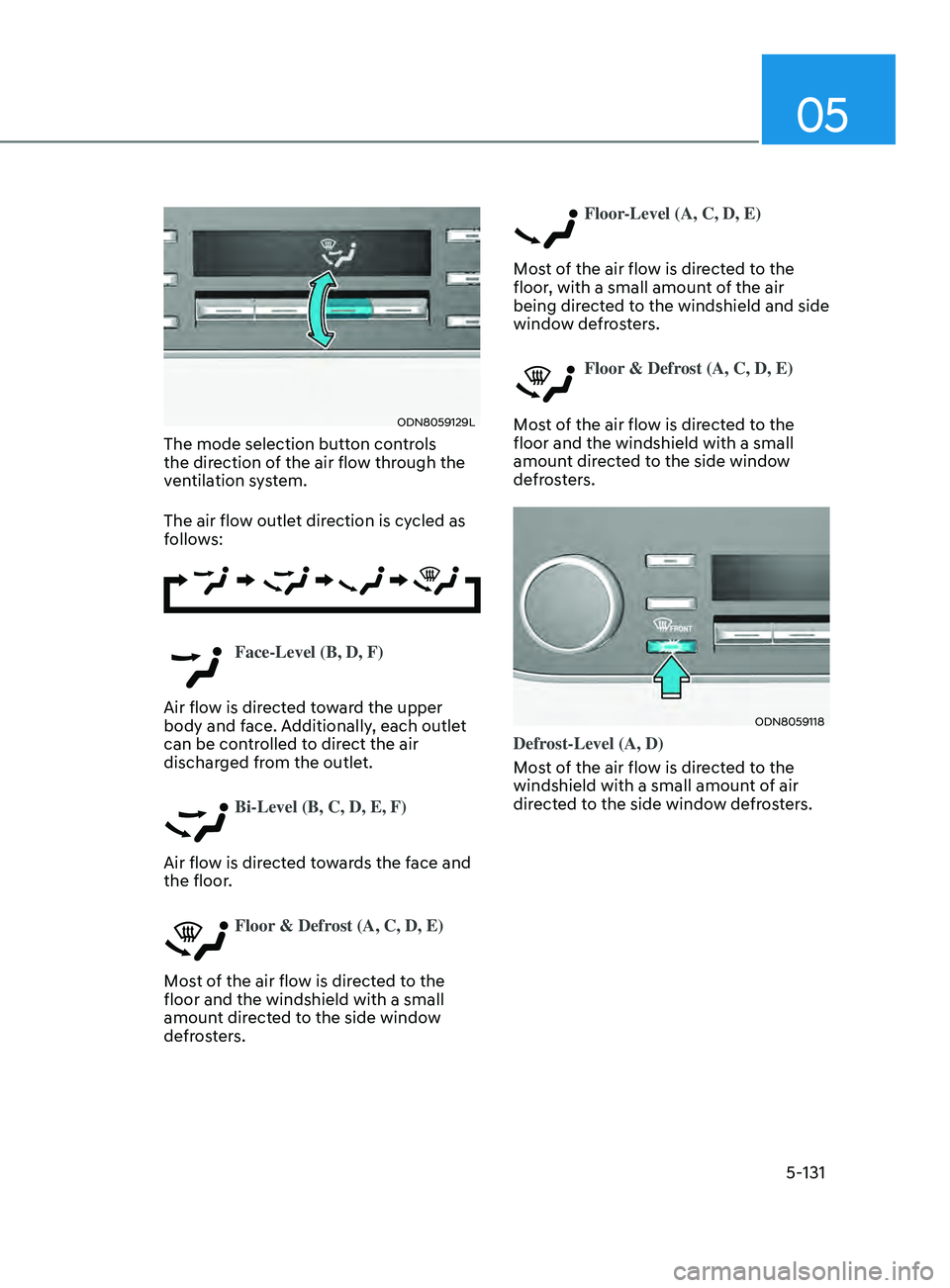
The mode selection button controls
the direction of the air flow through the
ventilation system.
The air flow outlet direction is cycled as
follows:
Face-Level (B, D, F)
Air flow is directed toward the upper
body and face. Additionally, each outlet
can be controlled to direct the air
discharged from the outlet.
Bi-Level (B, C, D, E, F)
Air flow is directed towards the face and
the floor.
Floor & Defrost (A, C, D, E)
Most of the air flow is directed to the
floor and the windshield with a small
amount directed to the side window
defrosters.
Floor-Level (A, C, D, E)
Most of the air flow is directed to the
floor, with a small amount of the air
being directed to the windshield and side
window defrosters.
Floor & Defrost (A, C, D, E)
Most of the air flow is directed to the
floor and the windshield with a small
amount directed to the side window
defrosters.
ODN8059118
Defrost-Level (A, D)
Most of the air flow is directed to the
windshield with a small amount of air
directed to the side window defrosters.
Page 287 of 546
Highway Driving Assist (HDA) ...................................................................6- 122System Setting and Operation ........................................................................\
.....6- 123
Warning Message ........................................................................\
.......................... 6-125
Rear Cross-Traffic Collision Warning (RCCW) /
Rear Cross-Traffic Collision-Avoidance Assist (RCCA)
...........................6-128
System Description ........................................................................\
....................... 6- 128
System Setting and Activation ........................................................................\
..... 6-129
Warning and System Control
........................................................................\
........ 6-131
Detecting Sensors
........................................................................\
.........................6-134
Limitations of the System
........................................................................\
............. 6-135
Special Driving Conditions ........................................................................\
6- 140Hazardous Driving Conditions ........................................................................\
....6- 140
Rocking the Vehicle ........................................................................\
..................... 6-140
Smooth Cornering
........................................................................\
......................... 6-141
Driving at Night
........................................................................\
............................. 6-141
Driving in the Rain
........................................................................\
......................... 6-141
Driving in Flooded Areas
........................................................................\
............... 6-142
Highway Driving
........................................................................\
............................ 6-142
Winter Driving ........................................................................\
....................6- 143Snow or Icy Conditions ........................................................................\
.................6-143
Win ter Precautions ........................................................................\
....................... 6-144
Vehicle load limit........................................................................\
................ 6-146
Tire Loading Information Label ........................................................................\
...6- 146
Trailer Towing ........................................................................\
......................6- 151
Lane Keeping Assist (LKA) ........................................................................\
..6-59LKA Operation ........................................................................\
................................ 6-61
LKA System Function Change ........................................................................\
....... 6-61
Warning Light and Message ........................................................................\
.......... 6-64
Limitations of the System ........................................................................\
.............. 6-65
Blind-Spot Collision Warning (BCW) /
Blind-Spot Collision-Avoidance Assist (BCA) ............................................6-67
System Description ........................................................................\
........................ 6-67
System Setting and Activation ........................................................................\
...... 6-68
Warning and System Control ........................................................................\
......... 6-70
Detecting Sensors
(Front view camera and Rear corner radar).......................................................... 6-72
Limitations of the System ........................................................................\
.............. 6-75
Declaration of Conformity ........................................................................\
...6-79The radio frequency components (Rear Corner Radar) complies: ..................... 6-79
Safe Exit Assist (SEA) ........................................................................\
.........6-80Function settings ........................................................................\
............................ 6-81
Function operation ........................................................................\
......................... 6-82
Function malfunction and limitations ................................................................... 6-84
Driver Attention Warning (DAW) ................................................................ 6-86System Setting and Operation ........................................................................\
...... 6-86
Resetting the System ........................................................................\
..................... 6-88
System Standby ........................................................................\
.............................. 6-89
System Malfunction ........................................................................\
....................... 6-89
Leading Vehicle Departure Alert ........................................................................\
... 6-91
Blind-Spot View Monitor (BVM) ................................................................. 6-94
Smart cruise control (SCC) ........................................................................\
. 6-95
Smart Cruise Control Switch ........................................................................\
......... 6-96
To Convert to Cruise Control Mode ...................................................................... 6-96
Smart Cruise Control Speed ........................................................................\
.......... 6-97
Smart Cruise Control Vehicle-to-Vehicle Distance ............................................ 6-103
Limitations of the System ........................................................................\
............ 6-108
Navigation-Based Smart Cruise Control ..................................................6-112System Setting and Operation ........................................................................\
..... 6-113
Lane Following Assist (LFA) ....................................................................... 6-116LFA Operation ........................................................................\
................................ 6-118
Warning Message ........................................................................\
.......................... 6-118
Limitations of the System ........................................................................\
............ 6-120
6
6. While Driving
Page 291 of 546
06
6 -7
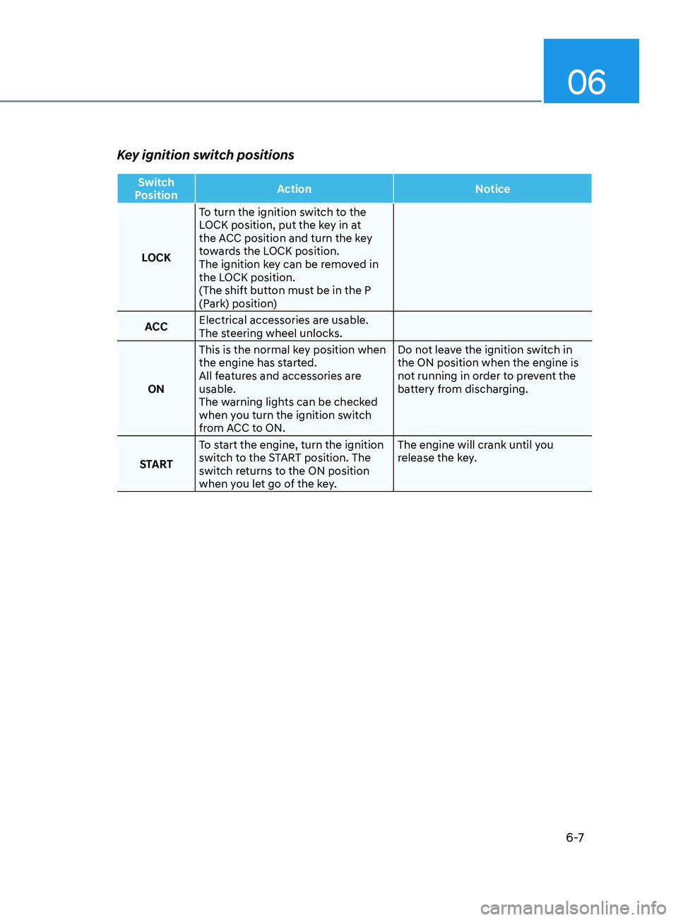
Key ignition switch positions
Switch
Position Action
Notice
LOCK To turn the ignition switch to the
LOCK position, put the key in at
the ACC position and turn the key
towards the LOCK position.
The ignition key can be removed in
the LOCK position.
(The shift button must be in the P
(Park) position)
ACC Electrical accessories are usable.
The steering wheel unlocks.
ON This is the normal key position when
the engine has started.
All features and accessories are
usable.
The warning lights can be checked
when you turn the ignition switch
from ACC to ON. Do not leave the ignition switch in
the ON position when the engine is
not running in order to prevent the
battery from discharging.
START To start the engine, turn the ignition
switch to the START position. The
switch returns to the ON position
when you let go of the key. The engine will crank until you
release the key.
Page 292 of 546
6-8
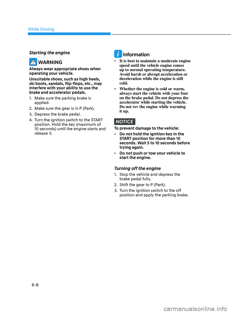
Starting the engine
WARNING
Always wear appropriate shoes when
operating your vehicle.
Unsuitable shoes, such as high heels,
ski boots, sandals, flip-flops, etc., may
interfere with your ability to use the
brake and accelerator pedals.
1.
Mak
e sure the parking brake is
applied.
2.
Mak
e sure the gear is in P (Park).
3.
Depr
ess the brake pedal.
4.
T
urn the ignition switch to the START
position. Hold the key (maximum of
10 seconds) until the engine starts and
release it.
Information
• It is best to maintain a moderate engine
speed until the vehicle engine comes
up to normal operating temperature.
Avoid harsh or abrupt acceleration or
deceleration while the engine is still
cold.
• Whether the engine is cold or warm,
always start the vehicle with your foot
on the brake pedal. Do not depress the
accelerator while starting the vehicle.
Do not rev the engine while warming
it up.
NOTICE
To prevent damage to the vehicle:
• Do not hold the ignition key in the
START position for more than 10
seconds. Wait 5 to 10 seconds before
trying again.
• Do not push or tow your vehicle to
start the engine.
Turning off the engine
1. Stop the vehicle and depress the
brake pedal fully.
2.
Shift the gear t
o P (Park).
3.
T
urn the ignition switch to the off
position and apply the parking brake.
While Driving
Page 295 of 546
06
6-11
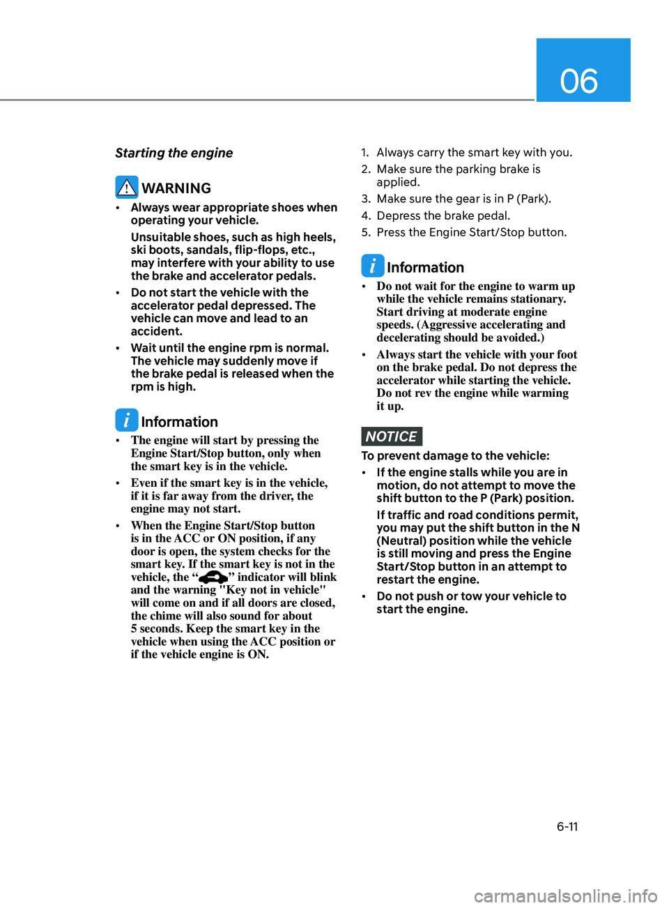
Starting the engine
WARNING
• Always wear appropriate shoes when
operating your vehicle.
Unsuitable shoes, such as high heels,
ski boots, sandals, flip-flops, etc.,
may interfere with your ability to use
the brake and accelerator pedals.
• Do not start the vehicle with the
accelerator pedal depressed. The
vehicle can move and lead to an
accident.
• Wait until the engine rpm is normal.
The vehicle may suddenly move if
the brake pedal is released when the
rpm is high.
Information
• The engine will start by pressing the
Engine Start/Stop button, only when
the smart key is in the vehicle.
• Even if the smart key is in the vehicle,
if it is far away from the driver, the
engine may not start.
• When the Engine Start/Stop button
is in the ACC or ON position, if any
door is open, the system checks for the
smart key. If the smart key is not in the
vehicle, the “
” indicator will blink
and the warning "Key not in vehicle"
will come on and if all doors are closed,
the chime will also sound for about
5 seconds. Keep the smart key in the
vehicle when using the ACC position or
if the vehicle engine is ON.
1. Always carry the smart key with you.
2.
Mak
e sure the parking brake is
applied.
3.
Mak
e sure the gear is in P (Park).
4.
Depr
ess the brake pedal.
5.
Pr
ess the Engine Start/Stop button.
Information
• Do not wait for the engine to warm up
while the vehicle remains stationary.
Start driving at moderate engine
speeds. (Aggressive accelerating and
decelerating should be avoided.)
• Always start the vehicle with your foot
on the brake pedal. Do not depress the
accelerator while starting the vehicle.
Do not rev the engine while warming
it up.
NOTICE
To prevent damage to the vehicle:
• If the engine stalls while you are in
motion, do not attempt to move the
shift button to the P (Park) position.
If traffic and road conditions permit,
you may put the shift button in the N
(Neutral) position while the vehicle
is still moving and press the Engine
Start/Stop button in an attempt to
restart the engine.
• Do not push or tow your vehicle to
start the engine.
Page 308 of 546
6-24
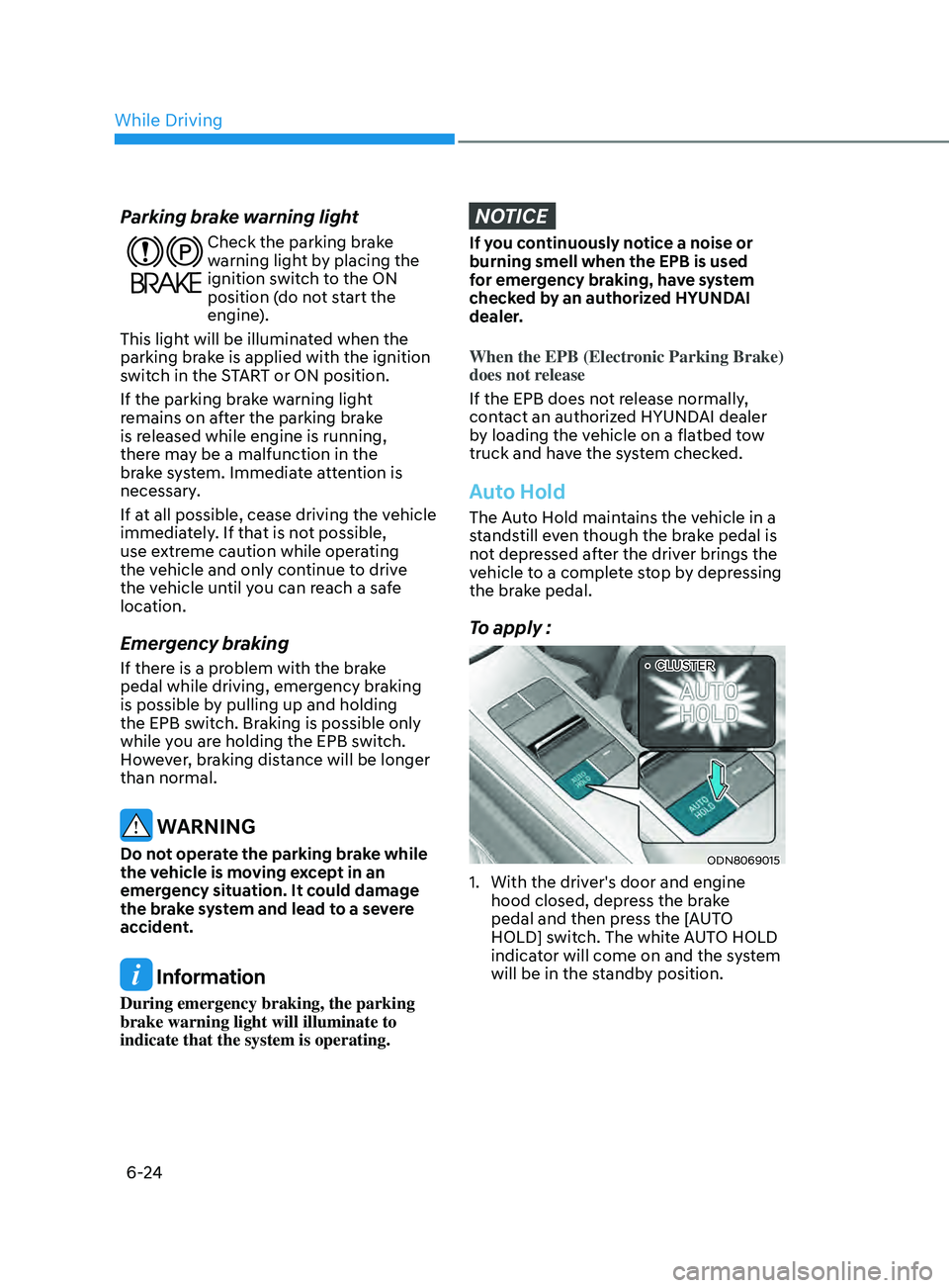
Parking brake warning light
Check the parking brake
warning light by placing the
ignition switch to the ON
position (do not start the
engine).
This light will be illuminated when the
parking brake is applied with the ignition
switch in the START or ON position.
If the parking brake warning light
remains on after the parking brake
is released while engine is running,
there may be a malfunction in the
brake system. Immediate attention is
necessary.
If at all possible, cease driving the vehicle
immediately. If that is not possible,
use extreme caution while operating
the vehicle and only continue to drive
the vehicle until you can reach a safe
location.
Emergency braking
If there is a problem with the brake
pedal while driving, emergency braking
is possible by pulling up and holding
the EPB switch. Braking is possible only
while you are holding the EPB switch.
However, braking distance will be longer
than normal.
WARNING
Do not operate the parking brake while
the vehicle is moving except in an
emergency situation. It could damage
the brake system and lead to a severe
accident.
Information
During emergency braking, the parking
brake warning light will illuminate to
indicate that the system is operating.
NOTICE
If you continuously notice a noise or
burning smell when the EPB is used
for emergency braking, have system
checked by an authorized HYUNDAI
dealer.
When the EPB (Electronic Parking Brake)
does not release
If the EPB does not release normally,
contact an authorized HYUNDAI dealer
by loading the vehicle on a flatbed tow
truck and have the system checked.
Auto Hold
The Auto Hold maintains the vehicle in a
standstill even though the brake pedal is
not depressed after the driver brings the
vehicle to a complete stop by depressing
the brake pedal.
To apply :
ODN8069015
1. With the driv er's door and engine
hood closed, depress the brake
pedal and then press the [AUTO
HOLD] switch. The white AUTO HOLD
indicator will come on and the system
will be in the standby position.
••CLUSTER
While Driving