2022 HYUNDAI SANTA CRUZ tailgate
[x] Cancel search: tailgatePage 306 of 598
Driving Your Vehicle
6-32
Warning messages
ONX4OB061006ONX4OB061006
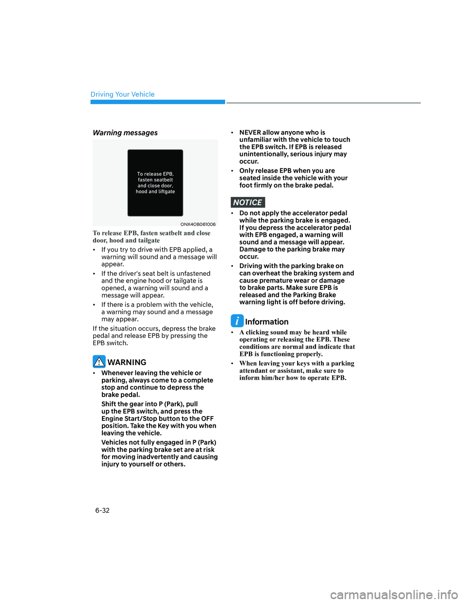
To release EPB, fasten seatbelt and close
door, hood and tailgate
• If you try to drive with EPB applied, a
warning will sound and a message will
appear.
• If the driver's seat belt is unfastened
and the engine hood or tailgate is
opened, a warning will sound and a
message will appear.
• If there is a problem with the vehicle,
a warning may sound and a message
may appear.
If the situation occurs, depress the brake
pedal and release EPB by pressing the
EPB switch.
WARNING
• Whenever leaving the vehicle or
parking, always come to a complete
stop and continue to depress the
brake pedal.
Shift the gear into P (Park), pull
up the EPB switch, and press the
Engine Start/Stop button to the OFF
position. Take the Key with you when
leaving the vehicle.
Vehicles not fully engaged in P (Park)
with the parking brake set are at risk
for moving inadvertently and causing
injury to yourself or others.
• NEVER allow anyone who is
unfamiliar with the vehicle to touch
the EPB switch. If EPB is released
unintentionally, serious injury may
occur.
• Only release EPB when you are
seated inside the vehicle with your
foot firmly on the brake pedal.
NOTICE
• Do not apply the accelerator pedal
while the parking brake is engaged.
If you depress the accelerator pedal
with EPB engaged, a warning will
sound and a message will appear.
Damage to the parking brake may
occur.
• Driving with the parking brake on
can overheat the braking system and
cause premature wear or damage
to brake parts. Make sure EPB is
released and the Parking Brake
warning light is off before driving.
Information
• A clicking sound may be heard while
operating or releasing the EPB. These
conditions are normal and indicate that
EPB is functioning properly.
• When leaving your keys with a parking
attendant or assistant, make sure to
inform him/her how to operate EPB.
Page 471 of 598
07
7-119
Surround View Monitor
Malfunction and Limitations
Surround View Monitor malfunction
When Surround View Monitor is not
working properly, or the screen flickers,
or the camera image does not display
properly, have the vehicle inspected by
an authorized HYUNDAI dealer.
Limitations of Surround View
Monitor
• When the vehicle is stopped for a long
time in winter or when the vehicle is
parked in an indoor parking lot, the
exhaust fumes may temporarily blur
the image.
• The screen may be displayed
abnormally, and an icon appears at
the top left side of the screen under
the following circumstances:
- The tailgate is opened
- The driver or front passenger door
is opened
- The side view mirror is folded
WARNING
• ALWAYS look around your vehicle
to make sure there are no objects
or obstacles before moving the
vehicle. What you see on the screen
may differ from the actual vehicle’s
location.
• The image shown on the screen may
differ from the actual distance of the
object. Make sure to directly check
the vehicle's surroundings for safety.
• Surround View Monitor is designed
to be used on a flat surface.
Therefore, if used on roads with
different heights such as curbs
and speed bumps, the image in the
screen my not look correct.
• Always keep the camera lens clean.
If the lens is covered with foreign
material, it may adversely affect
camera performance and Surround
View Monitor may not operate
properly. However, do not use
chemical solvents such as strong
detergents containing high alkaline
or volatile organic solvents (gasoline,
acetone, etc.). This may damage the
camera lens.
Page 560 of 598
Maintenance
9-52
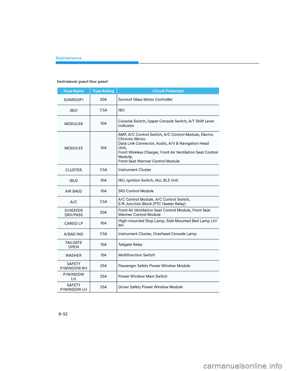
Instrument panel fuse panel
Fuse Name Fuse Rating Circuit Protected
SUNROOF120A Sunroof Glass Motor Controller
IBU17.5A IBU
MODULE610AConsole Switch, Upper Console Switch, A/T Shift Lever
Indicator
MODULE510AAMP, A/C Control Switch, A/C Control Module, Electro
Chromic Mirror,
Data Link Connector, Audio, A/V & Navigation Head
Unit,
Front Wireless Charger, Front Air Ventilation Seat Control
Module,
Front Seat Warmer Control Module
CLUSTER7.5A Instrument Cluster
IBU210A IBU, Ignition Switch, IAU, BLE Unit
AIR BAG210A SRS Control Module
A/C7.5AA/C Control Module, A/C Control Switch,
E/R Junction Block (PTC Heater Relay)
S/HEATER
DRV/PASS20AFront Air Ventilation Seat Control Module, Front Seat
Warmer Control Module
CARGO LP10AHigh-mounted Stop Lamp, Side Mounted Bed Lamp LH/
RH
A/BAG IND7.5A Instrument Cluster, Overhead Console Lamp
TAILGATE
OPEN10A Tailgate Relay
WASHER15A Multifunction Switch
SAFETY
P/WINDOW RH25A Passenger Safety Power Window Module
P/WINDOW
LH25A Power Window Main Switch
SAFETY
P/WINDOW LH25A Driver Safety Power Window Module
Page 563 of 598
![HYUNDAI SANTA CRUZ 2022 Owners Manual 09
9-55
Engine compartment fuse panel
Type Fuse NameFuse
RatingCircuit Protected
MULTI
FUSEMDPS80A MDPS Unit
COOLING FAN180A [G4KP] Cooling Fan Controller
COOLING FAN260A [G4KN] Cooling Fan Controlle HYUNDAI SANTA CRUZ 2022 Owners Manual 09
9-55
Engine compartment fuse panel
Type Fuse NameFuse
RatingCircuit Protected
MULTI
FUSEMDPS80A MDPS Unit
COOLING FAN180A [G4KP] Cooling Fan Controller
COOLING FAN260A [G4KN] Cooling Fan Controlle](/manual-img/35/41171/w960_41171-562.png)
09
9-55
Engine compartment fuse panel
Type Fuse NameFuse
RatingCircuit Protected
MULTI
FUSEMDPS80A MDPS Unit
COOLING FAN180A [G4KP] Cooling Fan Controller
COOLING FAN260A [G4KN] Cooling Fan Controller
B+260A ICU Junction Block (IPS7, IPS8, IPS9, IPS10, IPS11, IPS12)
B+360AICU Junction Block (Fuse - P/SEAT DRV, SAFETY P/
WINDOW RH, S/HEATER DRV/PASS, SUNROOF1, BED
STORAGE, Power Window Main Relay)
E-CVVT150A E/R Junction Block (E-CVVT Relay)
BLOWER40A E/R Junction Block (Blower Relay)
EPB140A ESC Module
REAR HEATED40A E/R Junction Block (Rear Heated Relay)
TRAILER 130A [G4KP] Trailer Connector
B+440AICU Junction Block (Fuse - DOOR LOCK, SAFETY P/
WINDOW LH, TAILGATE OPEN, AMP, IBU2, AIR BAG2,
CARGO LP, BRAKE SWITCH, MODULE9, Long Term
Load Latch Relay)
EPB260A ESC Module
FUEL PUMP20A E/R Junction Block (Fuel Pump Relay)
4WD20A AWD ECM
TRAILER 230A
[G4KN] Trailer Controller
AMS10A Battery Sensor
TRAILER 330A
[G4KN] Trailer Connector
ECU215A PCM/ECM
VACUUM PUMP120A
[G4KP] E/R Junction Block (Vacuum Pump Relay)
TCU115A [G4KN] PCM
ROOF LIGHT FRT15A Accessory Light Switch
E-CVVT220A [G4KP] ECM
HEATED MIRROR10AE/R Junction Block (Rear Heated Relay), Driver/
Passenger Power Outside Mirror
VACUUM PUMP210A [G4KP] ESC Module
TCU360A [G4KP] TCM
EOP60A [G4KP] Electronic Oil Pump
B+150A ICU Junction Block (IPS1, IPS3, IPS4, IPS5, IPS6,)
PTC HEATER50A E/R Junction Block (PTC Heater Relay)
INVERTER30A AC Inverter Module
Page 569 of 598
09
9-61
ONX4OB091009ONX4OB091009
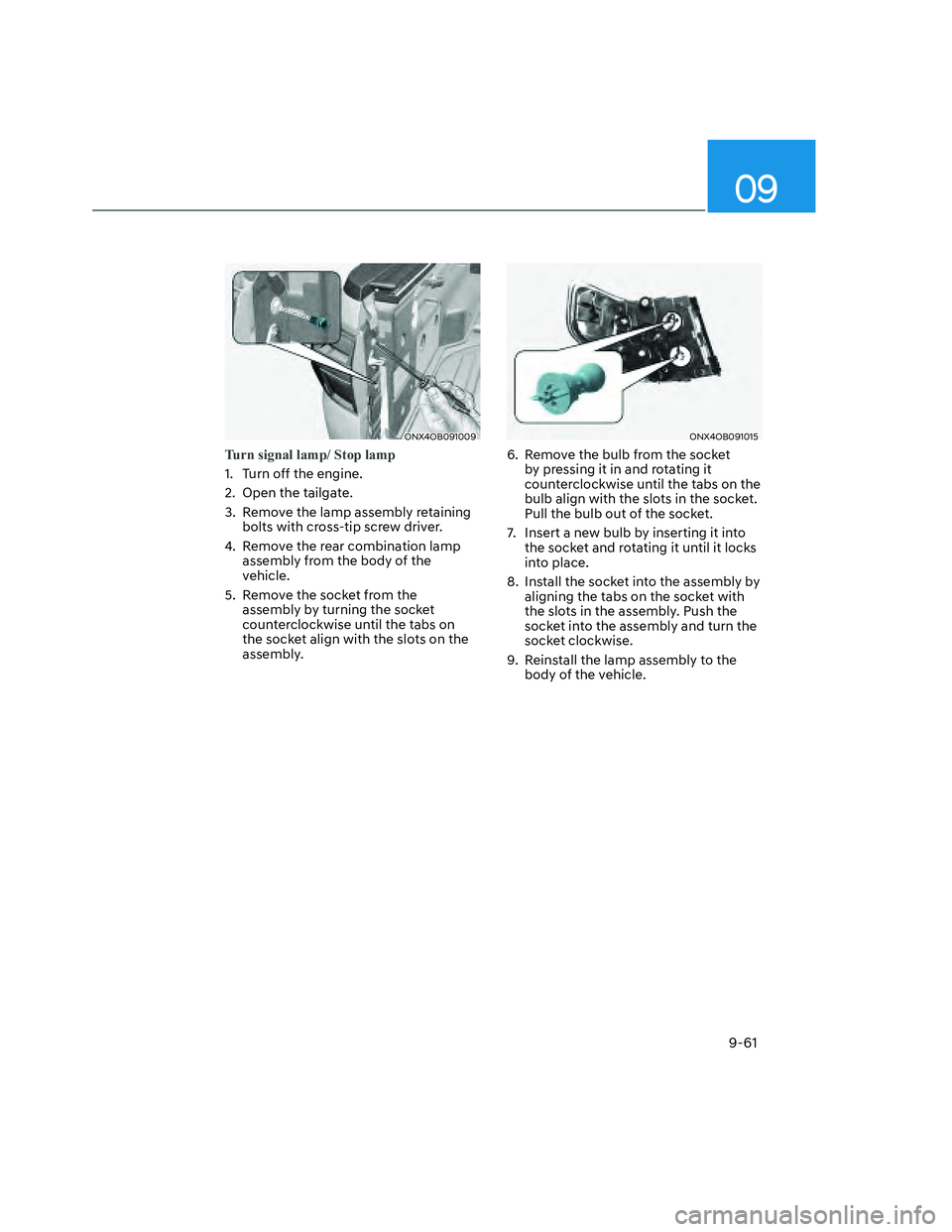
Turn signal lamp/ Stop lamp
1. Turn off the engine.
2. Open the tailgate.
3. Remove the lamp assembly retaining
bolts with cross-tip screw driver.
4. Remove the rear combination lamp
assembly from the body of the
vehicle.
5. Remove the socket from the
assembly by turning the socket
counterclockwise until the tabs on
the socket align with the slots on the
assembly.
ONX4OB091015ONX4OB091015
6. Remove the bulb from the socket
by pressing it in and rotating it
counterclockwise until the tabs on the
bulb align with the slots in the socket.
Pull the bulb out of the socket.
7. Insert a new bulb by inserting it into
the socket and rotating it until it locks
into place.
8. Install the socket into the assembly by
aligning the tabs on the socket with
the slots in the assembly. Push the
socket into the assembly and turn the
socket clockwise.
9. Reinstall the lamp assembly to the
body of the vehicle.
Page 589 of 598
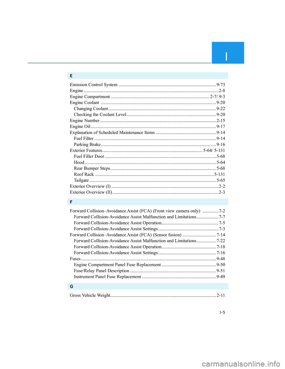
I
I-5
E
Emission Control System .................................................................................... 9-73
Engine .................................................................................................................... 2-8
Engine Compartment ..................................................................................... 2-7/ 9-3
Engine Coolant ................................................................................................... 9-20
Changing Coolant............................................................................................. 9-22
Checking the Coolant Level ............................................................................. 9-20
Engine Number .................................................................................................... 2-15
Engine Oil ............................................................................................................ 9-17
Explanation of Scheduled Maintenance Items .................................................... 9-14
Fuel Filter ......................................................................................................... 9-14
Parking Brake ................................................................................................... 9-16
Exterior Features...................................................................................... 5-64/ 5-131
Fuel Filler Door ................................................................................................ 5-68
Hood ................................................................................................................. 5-64
Rear Bumper Steps ........................................................................................... 5-68
Roof Rack ...................................................................................................... 5-131
Tailgate ............................................................................................................. 5-65
Exterior Overview (I) ............................................................................................ 2-2
Exterior Overview (II) ........................................................................................... 2-3
F
Forward Collision–Avoidance Assist (FCA) (Front view camera only) .............. 7-2
Forward Collision-Avoidance Assist Malfunction and Limitations................... 7-7
Forward Collision-Avoidance Assist Operation................................................. 7-5
Forward Collision-Avoidance Assist Settings .................................................... 7-3
Forward Collision–Avoidance Assist (FCA) (Sensor fusion) ............................. 7-14
Forward Collision-Avoidance Assist Malfunction and Limitations................. 7-22
Forward Collision-Avoidance Assist Operation............................................... 7-18
Forward Collision-Avoidance Assist Settings .................................................. 7-16
Fuses .................................................................................................................... 9-48
Engine Compartment Panel Fuse Replacement ............................................... 9-50
Fuse/Relay Panel Description .......................................................................... 9-51
Instrument Panel Fuse Replacement ................................................................ 9-49
G
Gross Vehicle Weight........................................................................................... 2-11