2022 HYUNDAI KONA emergency brake
[x] Cancel search: emergency brakePage 374 of 579
Driver assistance system
7-42
OOS070031L
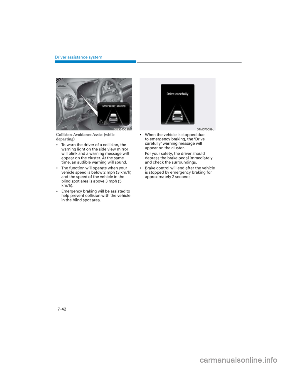
To warn the driver of a collision, the
warning light on the side view mirror
will blink and a warning message will
appear on the cluster. At the same
time, an audible warning will sound.
The function will operate when your
vehicle speed is below 2 mph (3 km/h)
and the speed of the vehicle in the
blind spot area is above 3 mph (5
km/h).
Emergency braking will be assisted to
help prevent collision with the vehicle
in the blind spot area.
OTM070059L
When the vehicle is stopped due
to emergency braking, the ‘Drive
appear on the cluster.
For your safety, the driver should
depress the brake pedal immediately
and check the surroundings.
Brake control will end after the vehicle
is stopped by emergency braking for
approximately 2 seconds.
Page 438 of 579
Driver assistance system
7-106
Rear Cross-Traffic Safety system
will operate when all the following
conditions are satisfied:
- The gear is shifted to R (Reverse)
- Vehicle speed is below 5 mph (8
km/h)
- The approaching vehicle is within
approximately 5 ft. (1.5 m) from the
left or right side of your vehicle
- The speed of the vehicle
approaching from the left and right
is above 3 mph (5 km/h)
Emergency braking will be assisted
to help prevent collision with
approaching vehicles from the left
and right.
WARNING
Brake control will end when:
-The approaching vehicle is out of the
detecting range
-The approaching vehicle passes
behind your vehicle
-The approaching vehicle does not
drive toward your vehicle
-The approaching vehicle speed slows
down
-The driver depresses the brake pedal
with sufficient power
OOS070113N
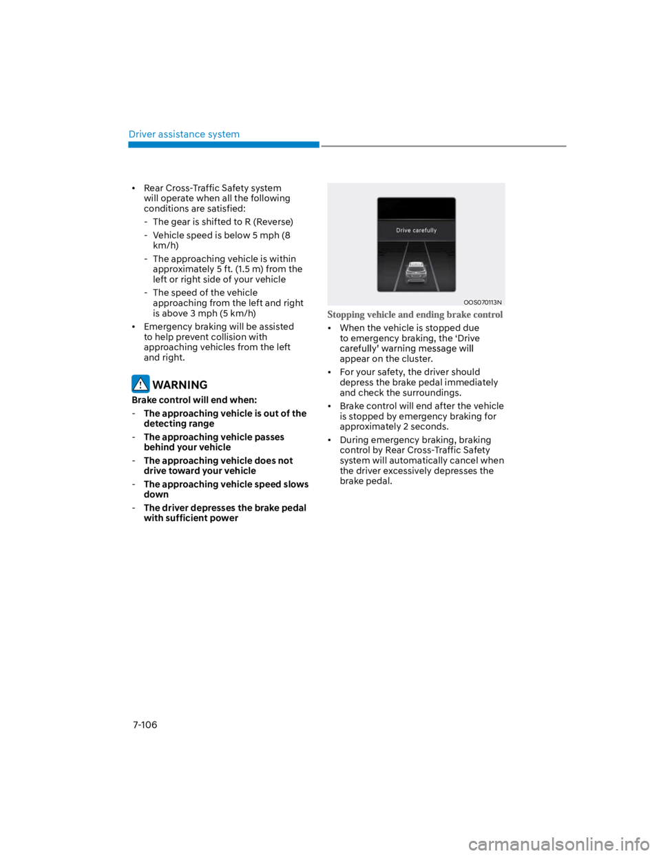
When the vehicle is stopped due
to emergency braking, the ‘Drive
appear on the cluster.
For your safety, the driver should
depress the brake pedal immediately
and check the surroundings.
Brake control will end after the vehicle
is stopped by emergency braking for
approximately 2 seconds.
During emergency braking, braking
control by Rear Cross-Traffic Safety
system will automatically cancel when
the driver excessively depresses the
brake pedal.
Page 462 of 579
Emergency situations
8-12
WARNING
TPMS
The TPMS cannot alert you to severe
and sudden tire damage caused by
external factors such as nails or road
debris.
If you feel any vehicle instability,
immediately take your foot off
the accelerator, apply the brakes
gradually and with light force, and
slowly move to a safe position off the
road.
WARNING
Protecting TPMS
Tampering with, modifying, or disabling
the Tire Pressure Monitoring System
(TPMS) components may interfere
with the system's ability to warn the
driver of low tire pressure conditions
and/or TPMS malfunctions. Tampering
with, modifying, or disabling the Tire
Pressure Monitoring System (TPMS)
components may void the warranty for
that portion of the vehicle.
Information
1.
2.
3.
Page 474 of 579
Emergency situations
8-24
Jack label
OOS067043
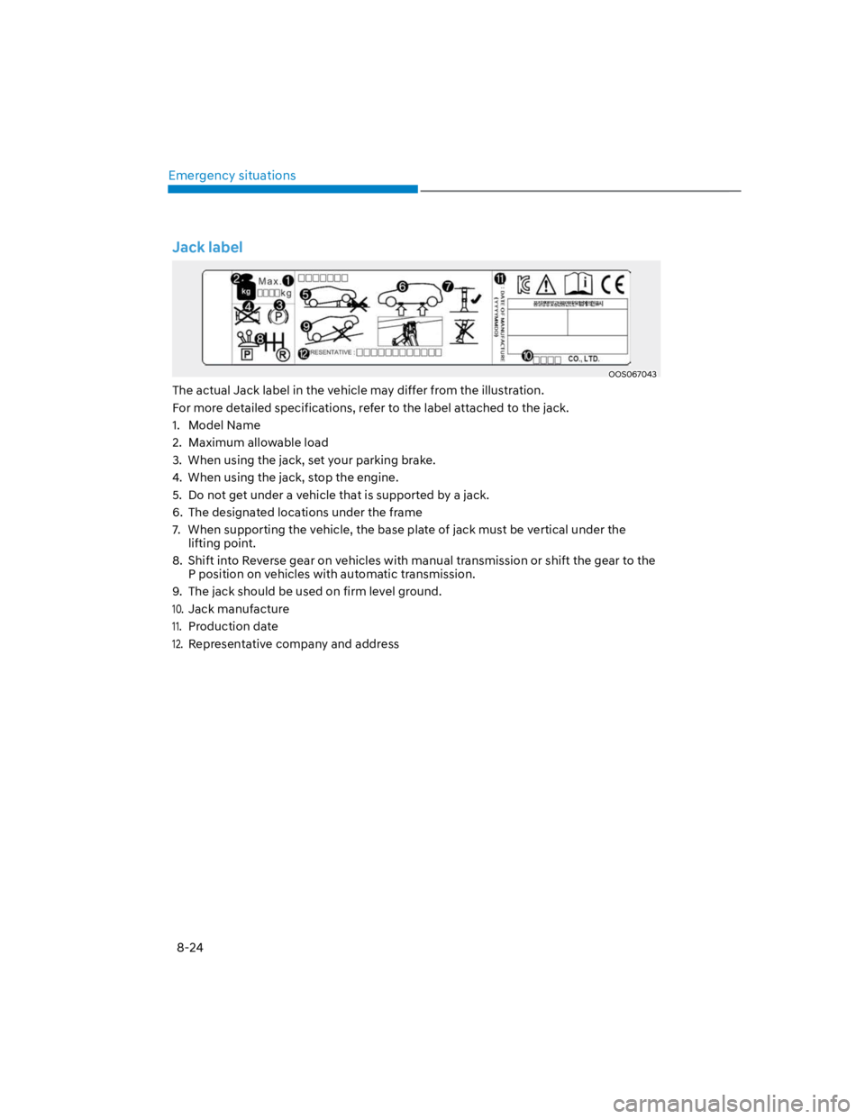
The actual Jack label in the vehicle may differ from the illustration.
For more detailed specifications, refer to the label attached to the jack.
1. Model Name
2. Maximum allowable load
3. When using the jack, set your parking brake.
4. When using the jack, stop the engine.
5. Do not get under a vehicle that is supported by a jack.
6. The designated locations under the frame
7. When supporting the vehicle, the base plate of jack must be vertical under the
lifting point.
8. Shift into Reverse gear on vehicles with manual transmission or shift the gear to the
P position on vehicles with automatic transmission.
9. The jack should be used on firm level ground.
10.
Jack manufacture
11.
Production date
12.
Representative company and address
Page 482 of 579

Emergency situations
8-32
Notes on the safe use of the Tire
Mobility Kit
Park your car at the side of the road
so that you can work with the Tire
Mobility Kit away from moving traffic.
To be sure your vehicle will not move,
even when you’re on fairly level
ground, always set your parking brake.
Only use the Tire Mobility Kit for
sealing/inflation passenger car tires.
Only punctured areas located within
the tread region of the tire can be
sealed using the tire mobility kit.
Do not use on motorcycles, bicycles
or any other type of tires.
When the tire and wheel are
damaged, do not use Tire Mobility Kit
for your safety.
Use of the Tire Mobility Kit may not be
effective for tire damage larger than
approximately 16 inch (4 mm).
Please contact the nearest HYUNDAI
dealer if the tire cannot be made
roadworthy with the Tire Mobility Kit.
Do not use the Tire Mobility Kit if a tire
is severely damaged by driving run flat
or with insufficient air pressure.
Do not remove any foreign objects
such as nails or screws that have
penetrated the tire.
Provided the car is outdoors, leave the
engine running. Otherwise operating
the compressor may eventually drain
the car battery.
Never leave the Tire Mobility Kit
unattended while it is being used.
Do not leave the compressor running
for more than 10 minutes at a time or
it may overheat.
Do not use the Tire Mobility Kit if the
ambient temperature is below -22°F
(30°C).
In case of skin contact with the
sealant, wash the area thoroughly
with plenty of water. If the irritation
persists, seek medical attention.
In case of eye contact with the
sealant, flush your eyes for at least 15
minutes. If the irritation persists, seek
medical attention.
In case of swallowing the sealant,
rinse the mouth and drink plenty of
water. However, never give anything
to an unconscious person and seek
medical attention immediately.
Long time exposure to the sealant
may cause damage to bodily tissue
such as kidney, etc.
Page 484 of 579
Emergency situations
8-34
WARNING
If your vehicle is equipped with a
rollover sensor, place the ignition
switch in the LOCK/OFF or ACC position
when the vehicle is being towed.
The side impact and curtain air bag
may deploy if the sensor detects the
situation as a rollover.
When towing your vehicle in an
emergency without wheel dollies:
1. Place the ignition switch in the ACC
position.
2. Place the shift lever in N (Neutral).
3. Release the parking brake.
CAUTION
Failure to place the shift lever in N
(Neutral) when being towed with the
front wheels on the ground can cause
internal damage to the transmission.
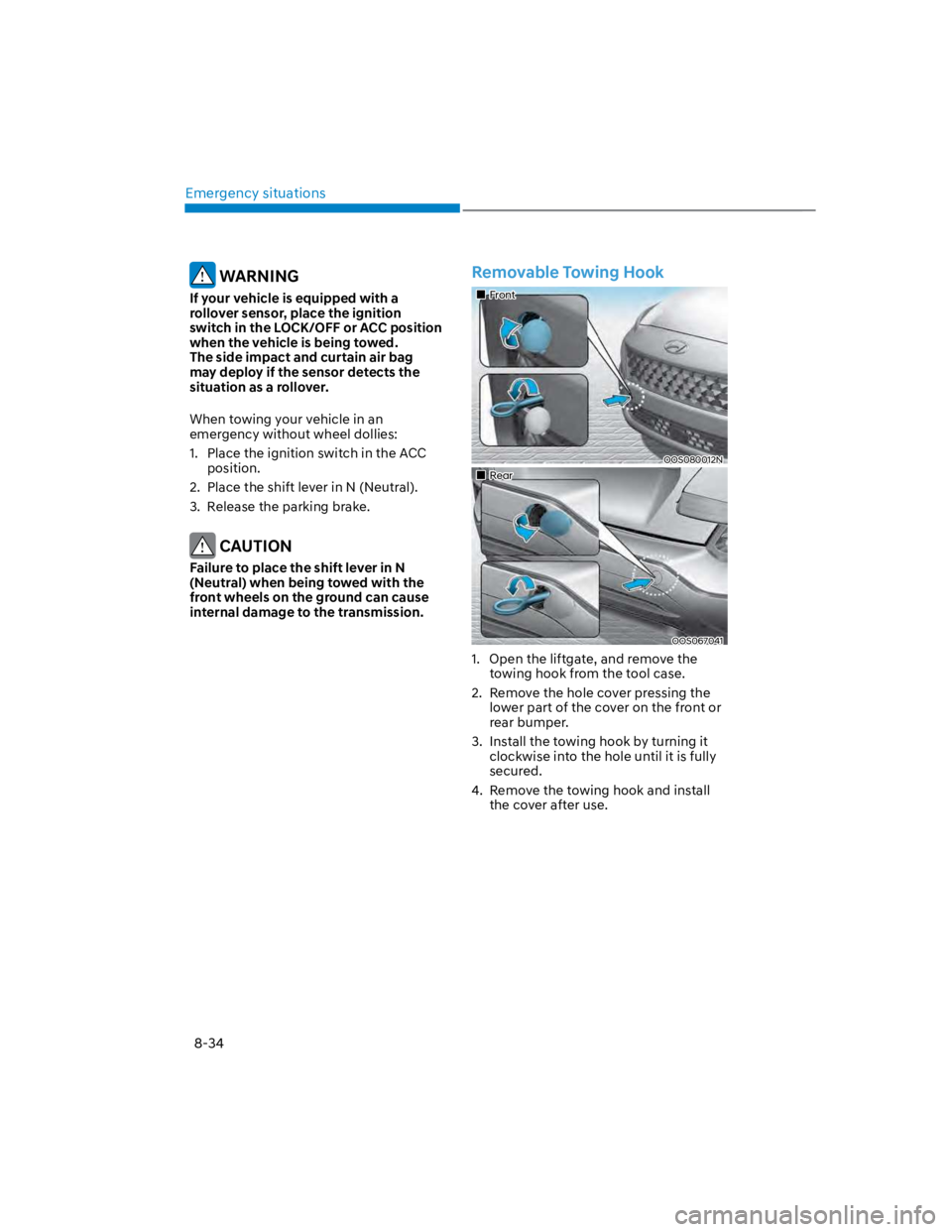
Removable Towing Hook
Front
OOS080012N
Rear
OOS067041
1. Open the liftgate, and remove the
towing hook from the tool case.
2. Remove the hole cover pressing the
lower part of the cover on the front or
rear bumper.
3. Install the towing hook by turning it
clockwise into the hole until it is fully
secured.
4. Remove the towing hook and install
the cover after use.
Page 485 of 579
08
8-35
Emergency Towing
If towing is necessary, we recommend
you have it done by an authorized
HYUNDAI dealer or a commercial tow
truck service.
If a towing service is not available in
an emergency, your vehicle may be
temporarily towed using a cable or chain
secured to the emergency towing hook
at the front (or rear) of the vehicle.
Use extreme caution when towing the
vehicle with a cable or chain. A driver
must be in the vehicle to steer it and
operate the brakes.
Towing in this manner may be done
only on hard-surfaced roads for a short
distance and at low speeds. Also, the
wheels, axles, power train, steering and
brakes must all be in good condition.
CAUTION
The driver must be in the vehicle for
steering and braking operations when
the vehicle is being towed. Passengers
other than the driver must not be in the
vehicle.
Always follow these emergency towing
precautions:
Place the ignition switch in the ACC
position so the steering wheel is not
locked. (if equipped)
Place the shift lever in N (Neutral).
Release the parking brake.
Depress the brake pedal with more
force than normal since you will have
reduced braking performance.
More steering effort will be required
because the power steering system
will be disabled.
Use a vehicle heavier than your own to
tow your vehicle.
The drivers of both vehicles should
communicate with each other
frequently.
Before emergency towing, check that
the hook is not broken or damaged.
Fasten the towing cable or chain
securely to the hook.
Do not jerk the hook. Apply steady
and even force.
Page 571 of 579

I
I-5
Engine Start/Stop button........................................................................................ 6-8
Engine Stop/Start button positions ..................................................................... 6-9
Remote start...................................................................................................... 6-12
Starting the engine............................................................................................ 6-10
Turning off the engine ...................................................................................... 6-11
Explanation of scheduled maintenance items ...................................................... 9-13
Fuel filter (for gasoline engine)........................................................................ 9-13
Intelligent variable transmission fluid ............................................................. 9-14
Parking brake.................................................................................................... 9-14
Propeller shaft .................................................................................................. 9-14
Exterior features......................................................................................... 5-61,5-115
Fuel filler door.................................................................................................. 5-64
Hood ................................................................................................................. 5-61
Liftgate ............................................................................................................. 5-62
Roof side rails................................................................................................. 5-115
Exterior overview (I) ............................................................................................. 2-2
Exterior overview (II) ............................................................................................ 2-4
F
Foreword................................................................................................................ 1-2
Forward Collision–Avoidance Assist (FCA) (front view camera only) ................ 7-2
Forward Collision-Avoidance Assist malfunction and limitations .................... 7-7
Forward Collision-Avoidance Assist operation.................................................. 7-5
Forward Collision-Avoidance Assist settings..................................................... 7-3
Forward Collision–Avoidance Assist (FCA) (Sensor fusion) ............................ 7-14
Forward Collision-Avoidance Assist malfunction and limitations .................. 7-21
Forward Collision-Avoidance Assist operation................................................ 7-18
Forward Collision-Avoidance Assist settings................................................... 7-16
Four wheel drive (4WD)...................................................................................... 6-46
Emergency precautions .................................................................................... 6-51
Four Wheel Drive (4WD) operation ................................................................ 6-47
Reducing the risk of a rollover ......................................................................... 6-52
Fuel requirements .................................................................................................. 1-5
Gasoline engine .................................................................................................. 1-5
Fuses .................................................................................................................... 9-45
Engine compartment panel fuse replacement................................................... 9-47
Fuse/relay panel description............................................................................. 9-49
Instrument panel fuse replacement................................................................... 9-46